autocom BFK-U Guide

WARRANT
Y
If your supplier has not given advice or demonstration on how to set up or use our products,
please check with them before sending any goods back for warranty.
A
ll Autocom products are warranted for a period of 12 months from the date of original
purchase, to the original purchaser, from an authorised Autocom retailer, against faulty
materials or workmanship, subject to the goods being used only as stated, and only for the
purpose as described in the instruction manuals.
No manufacturer's warranty applies to the goods where they are used for any other purpose
or in any other way than is explained in the instructions. Nor where the goods have been
subjected to misuse, neglect or accidental damage, or used with any other vendor’s products,
including incorrect mechanical or electrical installation, or where the goods have been
repaired, modified or altered, without the manufacturers written authorisation.
The manufacturer's warranty is limited to the goods being returned pre paid to the
manufacture's factory, with the original packaging and the original proof of purchase date.
The goods must be intact for our examination.
Where goods are accepted by the manufacturer, under the terms of the warranty, they will be
repaired free of charge or replaced (at the option of the manufacturer). Where the goods are
returned as faulty and are found not to be, an inspection, testing and return postage and
packing charge will be payable.
This warranty does not cover any consumable items such as batteries, replaceable hygiene
foam coverings for speakers & microphones, or any other items that are described within the
instruction manuals as being a consumable.
The manufacturer's warranty does not effect your statutory rights.
PLEASE CONTACT YOUR SUPPLIER OR AUTOCOM FOR ANY FURTHER
HELP OR INFORMATION. We service what we sell
UK Manufacturer & Distributor. Autocom Products Ltd.
20 Hawkes Drive, Heathcote Industrial Estate, Warwick. CV34 6LX. England. Tel: +44 (0)1926 431249 Email
enquiries@autocom.co.uk WEBSITE www.autocom.co.uk
USA Distributor. Top Gear NY 12159 USA Tel: 518 449 8677 www.autocomamerica.com
German Distributor. Green Frog & JF Motor Sport Tel: +49 6002 911331 www.greenfrog.de
Netherlands & Belgium Distributor. Splash Design. Tel: +31 413 389089 www.splashdesign.nl
Norway Distributor. Spare Parts Service AS Norway Tel: 67 907800 www.sps.no
Finland Distributor. Tokimoto Oy Finland Tel: +358 9 838 6540. www.tokimoto.fi
Switzerland Distributor. Hostettler A.G. Tel: 0041 41926 6111 www.hostettler.com
New Zealand Distributor. Dold Industries Ltd 00647 849 4392 www.dold@ventura-bike.com
If you need support in any country not listed, please contact Autocom UK.
V3
It is VERY IMPORTANT that
you fully read & understand
ALL of these instructions
before installation & use
These parts are designed ONLY for
use with Autocom domestic
motorcycle communication systems
INSTRUCTION MANUAL & WARRANTY for
Part 150. (BFK-U) Universal Bike Fitting Kit
This basic fitting kit gives you the typical parts that are frequently required for installing an Autocom system
to most types of bike. Please note that you may require some parts that are not included in the kit. This will
depend on the bike you have and how you want the intercom fitted. Please check with your supplier for more
advice. PLEASE NOTE all parts of this fitting kit are consumables and so have a limited warranty .
The kit includes
5 of BLACK Tie wraps .
5 of WHITE TIE wraps.
1 of 150mm Hook Velcro (rough)
1 of 300mm Loop Velcro (soft)
2 of Black plastics clips.
1 of Blue eyelet crimp terminal
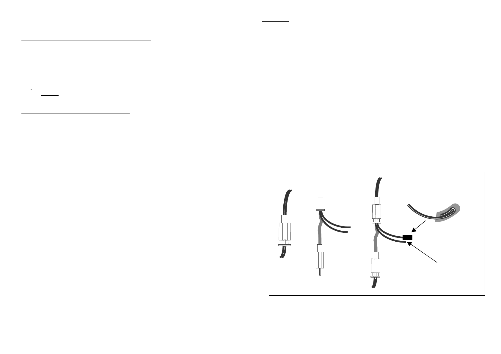
1 of Special electrical connector.(Fig 1 Part B)
1 of Black self-amalgamating tape
1 of 3.2mm Black heat shrink tubing
TIE wraps Use these where required to hold any cables in place. Make sure that you do not crush any
cables or tubing/breather/brake/clutch pipes on the bike by over tightening the tie wraps. Always cut the tie
wraps off squarely, as cutting them at an angle can leave a sharp pointed edge that can cause cuts.
Notes On Cables . Extreme care should be taken to ensure that the cables do not fall into the chain, wheel
or foul the steering etc, or be trapped or crushed by the seat or body panels. Pay particular attention to the
seat locking mechanism, which, if fouled, could cause problems with removing the seat. If required, use
some hard packing strips bonded in place either side of the cables, to prevent damaging the cables at any
pressure points, such as where the cables come from under the seat between the tank or body panels.
Avoid any sharp angles or edges that may damage or cut the cables.
Velcro. Cut one piece of hook and loop Velcro to about the same length as your intercom unit and use this
to fix the intercom to a clean, dry area, normally under the rear seat of the bike. (Ensure all surfaces are
clean and dry). If required use some of the remaining loop Velcro to cover any sharp edges, to protect the
cables.
Black clips. These can be used to hold the rider & passenger headset sockets neatly in place on the bike.
Make sure that the surface is flat, clean and dry before applying. Please note that the clips will tear off in the
event of an accident. They can sometimes be refitted using some suitable double-sided tape/glue.

Your Autocom system either comes with, or requires an optional power lead/adaptor to connect to your bikes 12-
volt supply. This power lead has two wires, one of which is RED (Positive +) and the other Black (Negative -)
CONNECTING THE NEGATIVE POWER LEAD TO YOUR BIKE.
Blue Eyelet Crimp Terminal Is for connecting your black negative power lead directly to your bikes battery
negative terminal. Position the main Autocom unit and lay all cables where you would like them to run and then try
the system with the engine running, listening for any electrical interference (A whining noise, engine speed related
is normally cause by the alternator, while a engine speed related ticking noise is normally related to HT spark plugs
or leads). If required, move the main unit and/or cables to locations that help eliminate any bike interference. Once
you are happy with your planned installation, fit the Blue Eyelet Crimp Terminal to the end of your black power
wire (If required, trim the wire to the required length before fitting the blue eyelet crimp). Connect the blue eyelet to
the bikes negative battery terminal. BE VERY CAREFUL WHEN WORKING WITH A BATTERY see your bikes
hand-book/manual about working with the battery.
CONNECTING THE POSITIVE LEAD TO YOUR BIKE
PLEASE NOTE if your bike has ABS braking and/or a brake light failure warning system you MUST consult
your bike supplier or manufacturer for approval before connecting to the brake light circuit. If connection to
the brake light circuit is not recommended, use some other ignition switched 12- volt supply, such as the rear tail
light live feed or any other recommended fused, switch ignition point.
If you can connect to the rear brake light feed our special electrical connector (See FIG 1 Part B) can offer a very
easy and quick, quality electrical connection to most bikes, BUT BEFORE DOING SO please check that the rear
brake pedal only operates the brake light with the ignition on.
To use our special connector, follow the wire which runs from the rear brake light switch to where it connects into
the bikes main wiring loom, normally by a two way block connector (See fig 1 parts A & C).
With the ignition switched off, unplug the connector and then plug our special connector (Fig 1 Part B) in line with
parts A & C. When you have done this separate the two red wires, making sure that they do not touch any
earth/chassis points and then turn the ignition on. Test to make sure that the brake lights work properly. If not,
remove our connector and consult a motorcycle electrician or your dealer. If your rear brake light is working properly
with part B connected in between parts A & C, proceed by testing which of the two red wires becomes live with the
ignition switched on, being careful that neither wires touch the bike frame.
When you have established the correct wire, turn the ignition off and insulate the other wire using the heat shrink
sleeve provided, as show in Fig 1. Do this by folding the end over about 12mm (1/2 inch). Slide the heat shrink over
the end so that it completely covers the bare end, and then apply heat until it shrinks down. Then solder the
intercom’s positive (RED) wire to the live lead of part B and then insulate and seal the solder joint with part of the
Black Self Amalgamating tape.
Note, if you connect to the wrong wire, the intercom will only work when the rear brake pedal is operated, in this
case you must disconnect and connect to the other wire.
150mm Black self amalgamating tape. Use this tape to insulate and seal electrical joints. Cut to required length
(allowing for the fact that it will stretch about 50% when applying. Carefully wrap it around the joint, stretching it
around the joint. The benefit of this special tape is that unlike ordinary electrical sticky tape this tape has no sticky
glue, which often breaks down when it get hot. Instead this special tape will weld itself into one piece of rubber
within about 30 minutes. By stretching it around the joint it will provide a permanent water/air tight seal, which can
easily and cleanly be removed at any time.
General Tips
Before you install the system, study the bike and assess the best location for the control box and the routes for the
cables, (usually under near the tail lights). Before you finally install the system you should connect the power and
plug in a headset and test the intercom with the engine running to make sure that it is not picking up any
undesirable interference .As you position the intercom and each cable you should give the engine a few revs to
check for any interference. If any H.T. ignition or alternator electrical noise is present , move the intercom and /or
cables to a location where there is no interference. When you have done this you can start fixing the box and cables
properly in place.
Avoid areas of high heat such as engine & exhaust.
Avoid ignition coils and H.T. leads (causes engine speed related interference). Avoid other electrical cables,
especially the regulator and ignition box and alternator (causes whining/engine speed related interference)
Avoid areas where the control box may get extremely wet, in particular where water may be under pressure, such
as in the front of the fairing or by spray from the wheels and jet washing. Apply an additional water protection to
stop direct heavy water contamination. Also try to mount the box in such a way that any moisture will run off and not
into the sockets/connections.
Normally the rider’s lead will follow the bike frame and come out in between the seat and tank. If you like, use one
of the black clips provided to hold the socket in place on the tank. Do the same with the pillion lead so that it comes
out near the back of the seat, to one side (normally LHS) near the grab handle?
Part B MUST be connected ONLY to an ignition switched, fused power supply on you
bike. NEVER connect directly across the bike battery, which could cause severe
damage and a risk of fire/burns etc. If you have any doubts you should consult a
qualified auto electrician.
Part ‘A’
(To bike loom)
Part ‘C’
(To Brake
Light Switch)
Part ‘B’
Part ‘C’
(To Brake
Light Switch)
Part ‘A’
(To bike loom)
Part ‘B’
Heat shrink
Sleeve
p
rovided
To Intercom
Positive Lead
Fig 1
This manual suits for next models
1
Other autocom Bicycle Accessories manuals