Autoenterprise CHARGE COMPLEX K Series User manual
CHARGE
COMPLEX «K»
Instruction manual

INSTRUCTION MANUAL CHARGE COMPLEX «K»
2
© Copyright
This documentation with all illustrations is the intellectual property of Autoenterprise. All
documentation is provided to the user for personal use only. This documentation may not
be reproduced or provided to others without our written permission. Any violation of the
law will be prosecuted.
Autoenterprise cannot be held liable for any direct or indirect damages
resulting from the use or operation of the electrical circuits of the
equipment or software described herein. The appliance should only be
used by trained and qualied personnel. Read the instructions carefully
before using the product. In addition, Autoenterprise reserves the right to
change any product described here without prior notice.

INSTRUCTION MANUAL CHARGE COMPLEX «K»
3
TABLE OF CONTENTS
1. Introduction............................................................................................4
2. Key information........................................................................................4
2.1 Information about the manual...........................................................................4
2.2 Warning signs...................................................................................................4
2.3 Liability and warranty........................................................................................5
2.4 Disposal information.........................................................................................6
2.5 Manufacturer’s label........................................................................................6
3. Application area, station specications ...........................................................7
3.1 Application area................................................................................................7
3.2 Complex Specications.....................................................................................7
3.3 Equipment modications...................................................................................9
3.4 General electrical safety information..................................................................9
4. Technical specication of the complex...........................................................10
4.1 Size and parameters of the complex..................................................................10
4.2Transportation of thecomplex...........................................................................13
4.3 Complex installation.......................................................................................13
4.4Complexconnection........................................................................................15
4.5 Complex storage.............................................................................................17
5. Maintenance of the complex.......................................................................18
6. Disassembly...........................................................................................20

INSTRUCTION MANUAL CHARGE COMPLEX «K»
4
1. INTRODUCTION
CHARGE COMPLEX «K»– is a high quality charging station (hereinafter referred to as «the
complex»), which is made using the latest solutions in the eld of power electronics and
technology, based on the modern components combined with the microcontroller signal
processing technology, which ensures high efciency, functionality and reliability of the
charger.
This, together with the software and accessible interfaces, provides a exible and productive
solution for electric vehicle charging that meets the highest quality standards.
The product is designed to control and convert the energy consumed from a three-phase
AC 220/380V to DC voltage and to control the AC voltage for charging an electric vehicle
battery.
The product is equipped with an intelligent microcontroller control system and
communication devices that allow for the exchange of information with the electric vehicle
and set the value of the charge current and voltage, according to the needs of the electric
vehicle in real time.
2. KEY INFORMATION
2.1 INFORMATION ABOUT THE MANUAL
This manual describes how to operate the charger properly and safely. Be sure to follow
the safety instructions given here, as well as any local safety regulations and general safety
instructions.
Before you put the charger into use, make sure that the instructions, the «Safety» paragraph
in particular, have been read through and understood completely. This manual is an integral
part of the station and and should therefore be kept in its immediate vicinity.
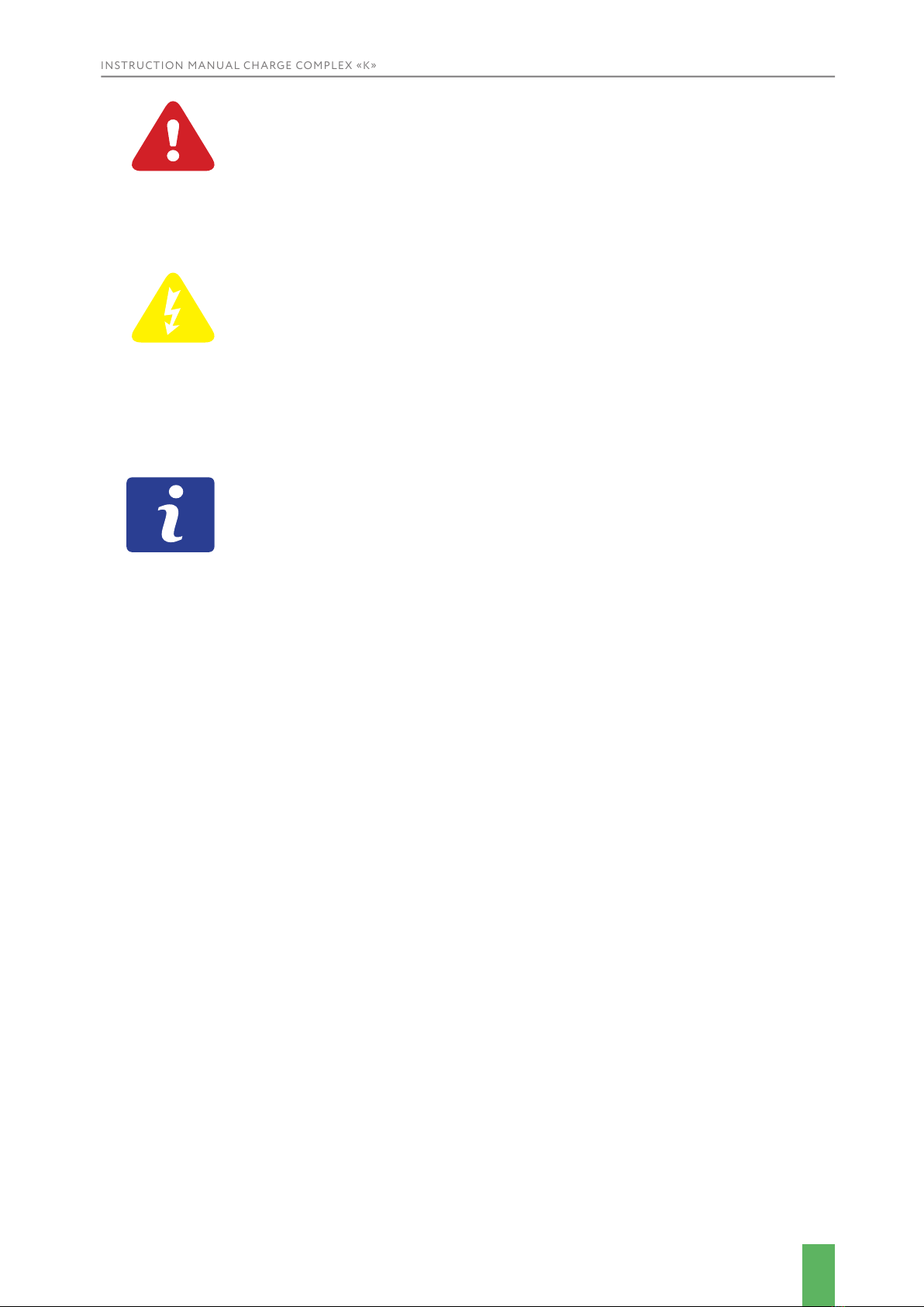
2.2 WARNING SYMBOLS
Important safety instructions in this manual are marked with symbols. These safety
instructions must be strictly adhered to. Always pay attention to them and follow the safety
instructions to avoid accidents, personal injury or material damage.
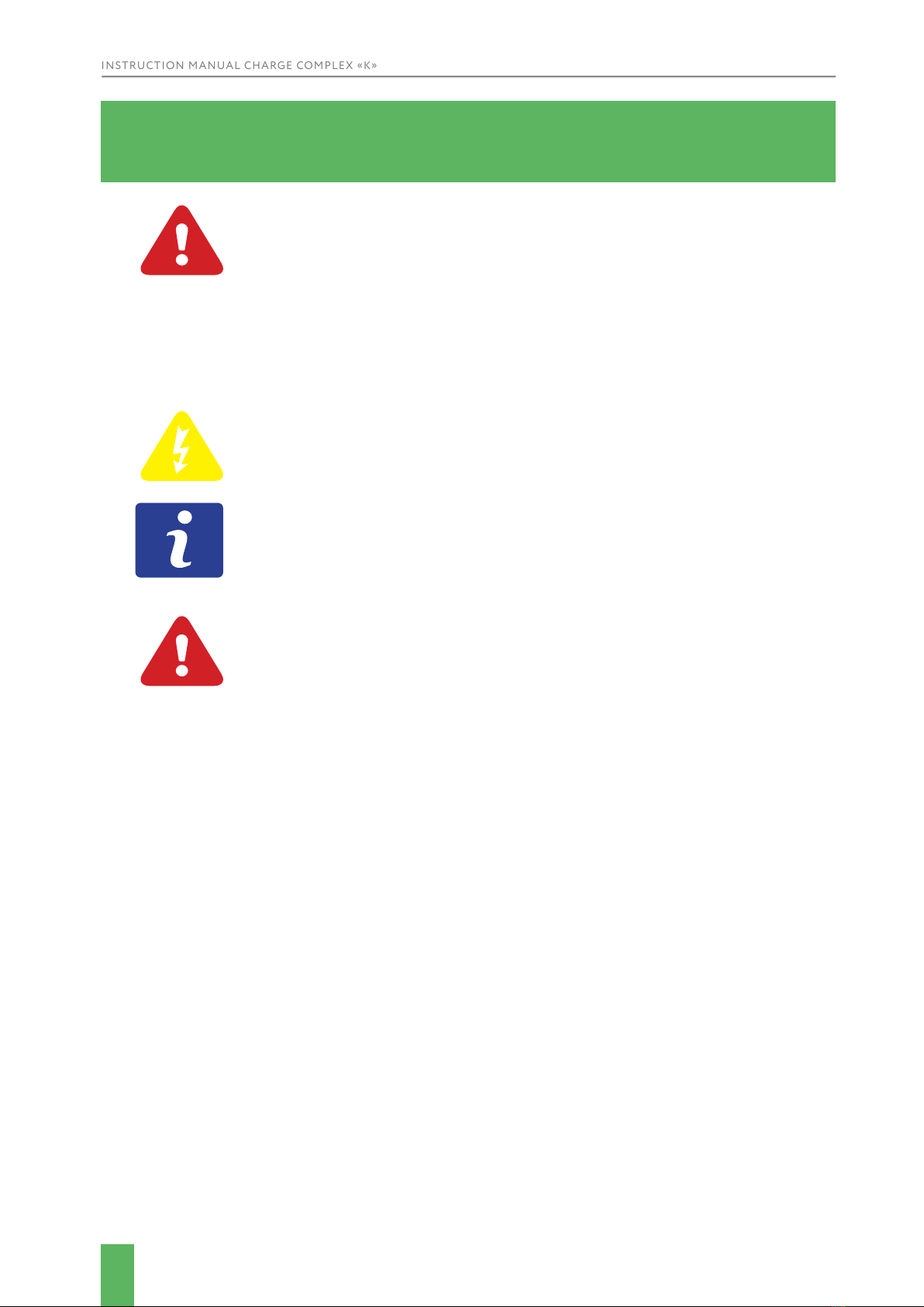
WARNING!
Risk of injury or death
This symbol indicates instructions that must be followed to avoid injury,
trauma or death.
INSTRUCTION MANUAL CHARGE COMPLEX «K»
5
WARNING!
Risk of material damage
This symbol indicates instructions which, if not followed, may result in
material damage, functional faults and/or machine breakdowns.
WARNING!
Danger - electrical current
This symbol alerts you to potentially dangerous situations involving
electric current. Failure to follow the safety instructions increases the risk
of serious injury or death. Caution should be exercised, especially during
maintenance and repairs.
ATTENTION!
This symbol indicates tips and information that should be adhered to in
order to ensure efcient and reliable operation of the product.
2.3 LIABILITY AND WARRANTY
All information, illustrations, sheets, specications and diagrams contained in these
operating instructions have been carefully compiled to the current state of the art at the
time of publication. We are not liable for errors, missing information or any subsequent
damages or consequential damages.
Strict adherence to the safety procedures described in these operating instructions and
special care when using the equipment are essential to prevent and reduce the likelihood of
injury or damage to the equipment. The manufacturer is not responsible for damage and/or
malfunctions caused by non-compliance with the instructions in this manual.
Additionally, the manufacturer will not be liable for any personal injury or material damage,
whether indirect or special, consequential, loss of business prots, business interruption
or loss of business information resulting from the use of the equipment described in this
manual.
Any software included in this equipment must only be used for the purposes for which it has
been provided to the User by the Autoenterprise for which it is strictly prohibited to make
any changes, conversions or copies (except for any necessary backups).
AutoEnterprise reserves the right to update any information, illustrations, sheets,
specications and diagrams contained in these operating instructions at any time without
prior notice.
INSTRUCTION MANUAL CHARGE COMPLEX «K»
6
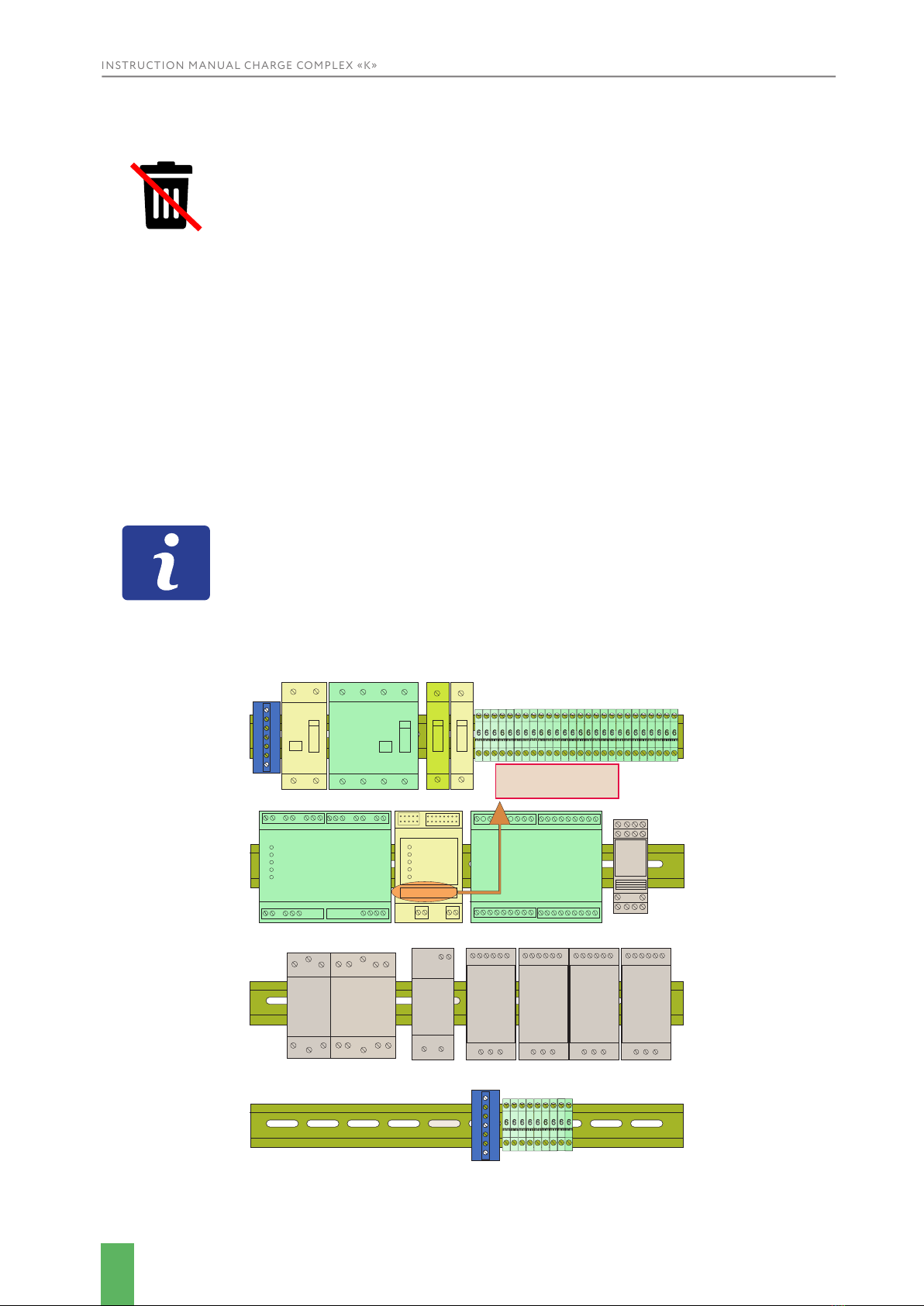
2.4 DISPOSAL INFORMATION
Do not dispose of the charging complex together with household
waste!
Electronic devices must be disposed of in accordance with the local
directives for the disposal of electronic and electrical waste. If you have
any further questions, please contact your supplier.
Use suitable tools if you need to disassemble the system. All individual parts must be sorted
by different types of material and disposed of in accordance with the regional guidelines for
the disposal of electronic and electrical waste.
2.5 MANUFACTURER’S LABEL
The marking on the charging complex is located on the GSM modem inside the complex on
the side of the control panel (side 1) and consists of alphabetic and digital symbols (example:
M123456).
This information is important for setting up, troubleshooting and ordering
spare parts for the station.
ERM4-012
DCL
A2 A1
EVCC-DC-003
EVCC-АC-003 EVCC-GSM
002
MW
MDR
40-12
L
N
+V +V -V -V
MW
MDR
40-12
L
N
+V +V -V -V
MW
MDR
40-12
L
N
+V +V -V -V
MW
MDR
40-12
L
N
+V +V -V -V
MW
HDR
30-12
V+
V-
NL
on
ETI EFI6-4 40/0,03-AC
on
ETI C6
on
ETI C25
on
ETI
on
ETI
EFI6-2 63/003-AC
монтажная компоновка зарядного комплекса - сторона 1
A1
A2
ETI
RA40-40
fA1
A22
ETI
R63-20
монтажная компоновка «Мультистанция» сторона 2
-
+
DGR 150
LEM HO 150 S
EVR150-12S
ETI 6 3P C32
on on on
ETI 6 3P C32
on on on
ETI 6 3P C32
on on on
ETI 6 3P C32
on on on
DGR 150DGR 150
DGR 150
(Вер. 1_1 27.05.2019)
EVR150-12S
DGR 150 DGR 150
М123456
Серийный номер
зарядного комплекса
SERIAL NUMBER
INSTRUCTION MANUAL CHARGE COMPLEX «K»
7
IEC61851-1 charging mode Type 1, Type 2, CHAdeMO, CCS (Type 2)
Rated input voltage 3 phase 380V
Input voltage deviation
limits, %, max
+-10
Nominal mains frequency 50 Hz
Main ports:
Chademo
1 p.
Output power, max. 60 kWh
Maximum cable current 150A
Maximum connector voltage 550V
Cable length 6,5 m
3. APPLICATION AREA, STATION SPECIFICATIONS
3.1 APPLICATION AREA
The charger is designed exclusively for charging electric vehicles.
For information about the materials, please contact Autoenterprise sales
representative or contact the Autoenterprise technical support team
The following sections should also be followed as part of the intended use:
•Only charge compatible electric vehicles.
•Failure to follow the instructions for use, maintenance and repair described in these
operating instructions excludes any liability on the part of the manufacturer in the event of a
defect.
•The system must only be operated, maintained and repaired by personnel familiar with the
intended use and hazards!
•Carry out maintenance and repairs in accordance with the specifications in these operating
instructions.
•The unit may only be operated with equipment and spare parts supplied or listed in the
spare parts and consumables lists.
•Using of the system in other areas is contrary to its intended purpose. The manufacturer is
not responsible for any damage to the equipment resulting from such use. The user is solely
responsible for any damage resulting from improper use of the system.
3.2 COMPLEX SPECIFICATIONS

INSTRUCTION MANUAL CHARGE COMPLEX «K»
8
CCS
Type 1
Type 2
1 p.
Output power, max. 60 kWh
Maximum cable current 150A
Maximum connector voltage 550V
Cable length 6,5 m
1 p.
Output power, max. 19 kWh
Maximum cable current 80 A
Maximum connector voltage 240V
Cable length 6,5 m
1 p.
Output power 45 kWh
Maximum cable current 63A
Cable length 6,5 m
Number of vehicles
simultaneously connected to
one Charging Station
3
Access types
RFID card
Mobile application
Chip tag (optional)
Stand-alone operation
Delivery contents Charging station, user manual
Charging station dimensions 314х1056х2122 mm
Type of installation Floor/Wall mounting
Online device monitoring Yes
Current adjustment Yes
Possibility to manage rates of the
station Yes
Single body version Yes
Digital display to indicate the amount of
electricity consumed Yes
User interface management The menu functions are controlled via
the buttons on the control panel or via
the application. Mechanical emergency
shutdown button for the station.
Enclosure material Steel with anticorrosive coating
Mechanical protection IK10
Case protection class IP65
CHARGING COMPLEX FEATURES

INSTRUCTION MANUAL CHARGE COMPLEX «K»
9
In emergency situations, the charging complex disconnects the input power circuits by
means of differential relays. The charging complex control system is powered from the
mains via an additional circuit breaker. The output cable is connected by the sealing sleeves/
cable glands. After the voltage is switched on, the initial availability of the charger is not
more than 1 minute. The charging complex is designed for continuous operation. Switching
the operation modes of the charger is carried out under the control of a communication
microcontroller providing communication with the car. An emergency stop button is located
on the front side of the charging station in the DC charging mode. Relative humidity should
not exceed 95% without condensation.
3.3 EQUIPMENT MODIFICATIONS
It is strictly forbidden to change, modify or alter the machine in any way without the explicit
consent of the manufacturer.
All signs, stickers and pictograms attached to the machine must be visible, legible and cannot
be removed. Signs, labels or pictograms that have become damaged or illegible must be
replaced immediately. Please contact AutoEnterprise to coordinate such questions.
3.4 GENERAL ELECTRICAL SAFETY INFORMATION
Follow the safety instructions to avoid injury and material damage when working with the
device.
Failure to follow these instructions can result in injury and damage to or destruction of the
product.
Ignoring the safety recommendations and instructions in this manual will relieve the
manufacturer and his authorized representatives of all liability and claims.
During the installation and operation of the charging complex the following
should be adhered to: «Rules of electric installations», «Rules of technical
operation of electric installations for consumers», «Safety rules for the
operation of electric installations for consumers» in the part concerning electric
installations up to 1000 V GOST 22261-94.
The method of human protection against electric shock charger corresponds to class 1 of
GOST 12.2.007.0-75.
Maintenance and change of the circuit of connection of the product should be carried out
after de-energizing the input circuits with the help of external disconnecting devices and
disconnecting the charger from the electric vehicle. It should be noted that in the presence
of voltage at the mains input, at the other terminals of the product, due to the presence of
internal connections, there may also be life-threatening voltage.
Power cable entry from below Yes
Gross/net weight (without DC modules), kg 180
Ambient temperature from -50°C to +50°C

INSTRUCTION MANUAL CHARGE COMPLEX «K»
10
4. COMPLEX SPECIFICATIONS
4.1 CHARGING COMPLEX DIMENSIONS AND PARAMETERS
DESCRIPTION OF CONNECTORS AND PARAMETERS OF THE CHARGING COMPLEX
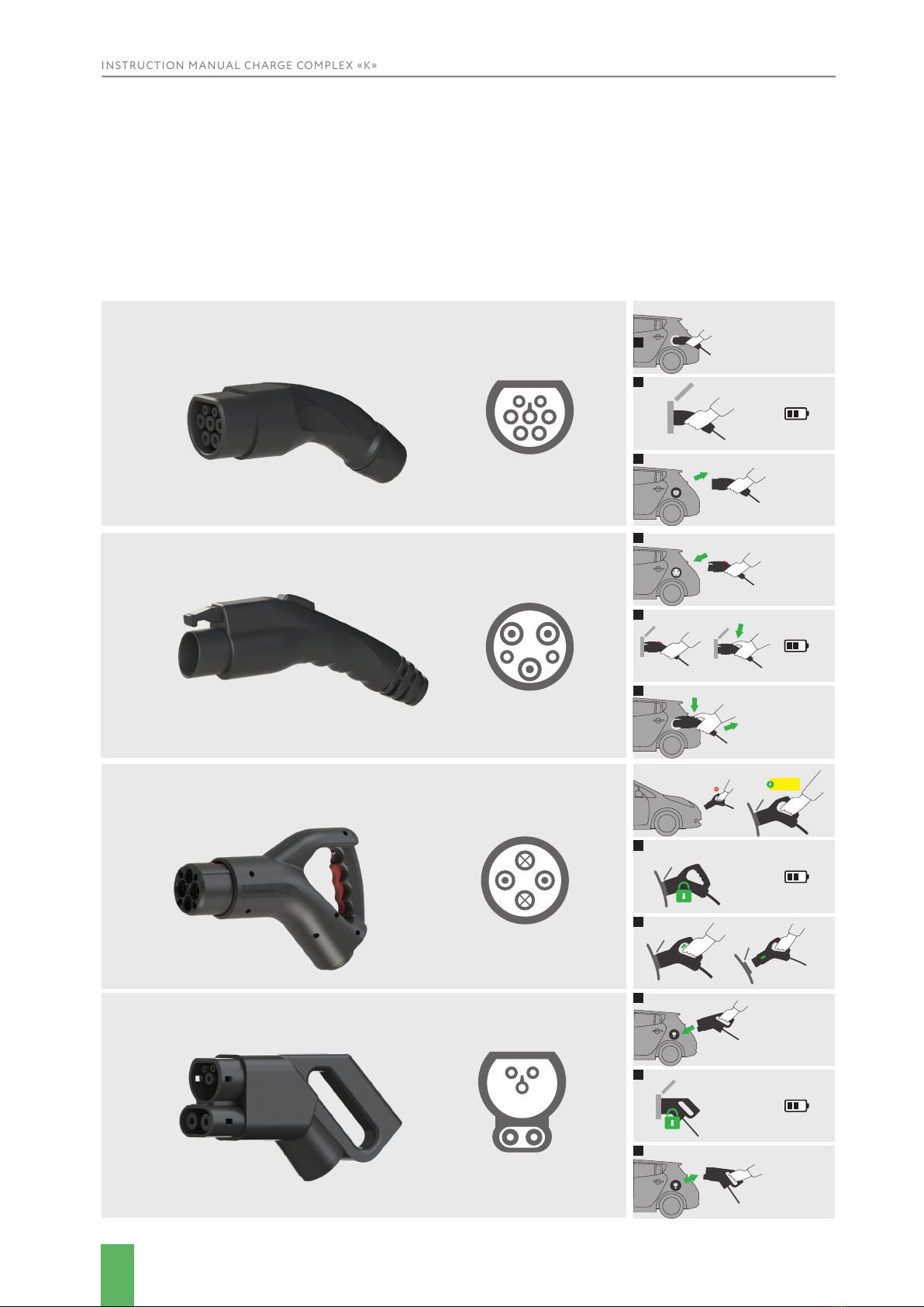
Types of connectors for connecting the charging cable to the electric vehicle:
Type 1 (SAE J1772);
Type 2 (Mennekes);
CHAdeMO;
CCS (Type 2).
The station is structurally designed as a monoblock mounted on a pillar and has the
following control and management bodies:
• Encased charging station on a pillar – 1 pc.
• Connector «Type 1» (with cable) - 1 pc.
• Connector « Type 2» (with cable) - 1 pc.
• Connector « CHAdeMO» (with cable) - 1 pc.
• Connector «CCS (Type 2)» (with cable) - 1 pc.
• Information display - 1 pc
All connectors are permanently installed in the charging complex case. For easy
transportation, the stand is separated from the charging station and packaged separately.
FRONT VIEW SIDE VIEW

INSTRUCTION MANUAL CHARGE COMPLEX «K»
11
CHARGE COMPLEX «K»
Socket type Quantity Current,
АMax power, kWh Max voltage, V
Type 1 (SAE J1772) 1 80 19 240
Type 2 (Mennekes) 1 63 45 380
CHAdeMO * 1 150 60 550
CCS (Type 2) * 1 150 60 550
CHARGE COMPLEX «K» - 3
Socket type Quantity Current,
АMax power, kWh Max voltage, V
Type 1 (SAE J1772) 1 80 19 240
Type 2 (Mennekes) 1 3х63 43 380
CHAdeMO 1 125 60 480
CCS (Type 2) 1 125 60 480
CHARGE COMPLEX «K» - 2
Socket type Quantity Current,
АMax power, kWh Max voltage, V
Type 1 (SAE J1772) 1 80 19 240
Type 2 (Mennekes) 1 3х63 43 380
CHAdeMO * 1 84 40 480
CCS (Type 2) * 1 84 40 480
CHARGE COMPLEX «K» - 1
Socket type Quantity Current,
АMax power, kWh Max voltage, V
Type 1 (SAE J1772) 1 80 19 240
Type 2 (Mennekes) 1 3х63 43 380
CHAdeMO * 1 42 20 480
CCS (Type 2) * 1 42 20 480
CHARGING STATION MODIFICATIONS
The charging station is available in the following congurations
INSTRUCTION MANUAL CHARGE COMPLEX «K»
12
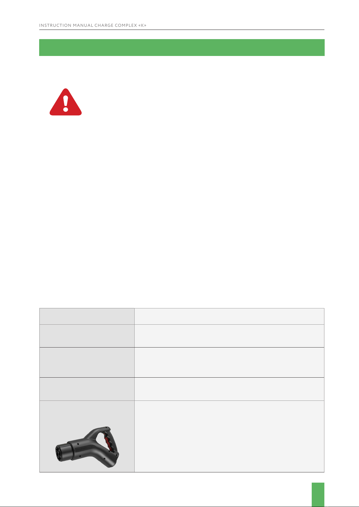
CHAdeMO connector.
CHAdeMO connectors have a lock button.
2
3
CCS connector.
1
2
3
AC connector
Type2
Connector AC.
Type1
1
2
2
3
3
1
The charging complex is designed for the installation of 1 «KEHUA 20» 3 DC modules.
The emergency stop button is located at the bottom of the unit housing.
When the emergency stop button is pressed in DC charging mode, the charging station
control circuit is automatically deactivated and the red LED on the information display
blinks continuously at a frequency of 2 times/second.
In order to continue the operation of the automatic stop button, it is necessary to reset the
button manually (pull the base of the button downwards).
click

INSTRUCTION MANUAL CHARGE COMPLEX «K»
13
The charging complex is designed for installing 4 DC modules of «PRE, 12 kW» model. The
emergency stop button is located at the bottom of the unit housing.
When the emergency stop button is pressed in DC charging mode, the charging station
control circuit is automatically deactivated and the red LED on the information display
blinks continuously at a frequency of 2 times/second.
In order to continue the operation of the automatic stop button, it is necessary to reset the
button manually (pull the base of the button downwards).
4.2 TRANSPORTATION OF THE COMPLEX
WARNING
There is a risk of injury from falling parts during transport, loading or
unloading of the station.
ATTENTION
The charger may be damaged or destroyed if it is mishandled during
transportation.
FOR THIS REASON, THE FOLLOWING SAFETY INSTRUCTIONS MUST BE STRICTLY
ADHERED TO:
Transport the charging complex with the utmost care.
Take into account the centre of gravity of the charging system during transportation (minimize the
risk of tipping over).
Take measures to prevent the charger from sliding sideways.
Transport the charger as carefully as possible to avoid damaging it.
Protect the charger from damage during transportation by using belts and inserts and leave
sufcient clearance between other objects to be transported.
Temperature during transportation:
Min: 10 °C
Max: 40 °C
4.3 COMPLEX INSTALLATION
When choosing the location of the charger, the following conditions must be met: there
must be a distance of at least 1 meter between the charger and the wall or any obstacle.
Nothing should be placed on the charger. Sufcient space must be left at the front and back
of the charger for maintenance.
RECOMMENDATIONS ON THE CHARGING COMPLEX INSTALLATION.
The complex is installed on a concrete base of 1300x1300x500 mm in size. It is
recommended to prepare a special foundation with an installed metal base (an example of a
base structure is shown in the drawing below).

INSTRUCTION MANUAL CHARGE COMPLEX «K»
14
The base is to be poured with concrete. The ground at the
place of installation of the charging station must ensure
high stability of the base. There should be no underground
cables or pipes in the area around the foundation.
The foundation usually settles for about a week. Once
the concrete has stood, you may to proceed with the
installation.
The base size of the charging station post is shown in the
gure below, plate should be 8 mm thick.
20
41
235
290
WARNING
Along with the preparing of the foundation, it is necessary to lay the power cable (not included in the
delivery set). When routing the power cable, appropriate insulation must be used.
It is recommended to lay and connect the power cable inside the charging station’s rack before
installing it on a concrete base, while removing the insulation from the station side at a distance of
300 mm in advance.
Only qualied personnel should connect the power cable to the AC mains.
The recommended cross section of the power cable is a copper multi-wire conductor with a cross
section of 5x50 mm2.
Before connecting the complex to the power supply, it is recommended to install an AC circuit
breaker between the complex and the power supply network. It is necessary for the further
maintenance of the complex. We recommended to use a 3-pole circuit breaker 160 A.
INSTRUCTION MANUAL CHARGE COMPLEX «K»
15
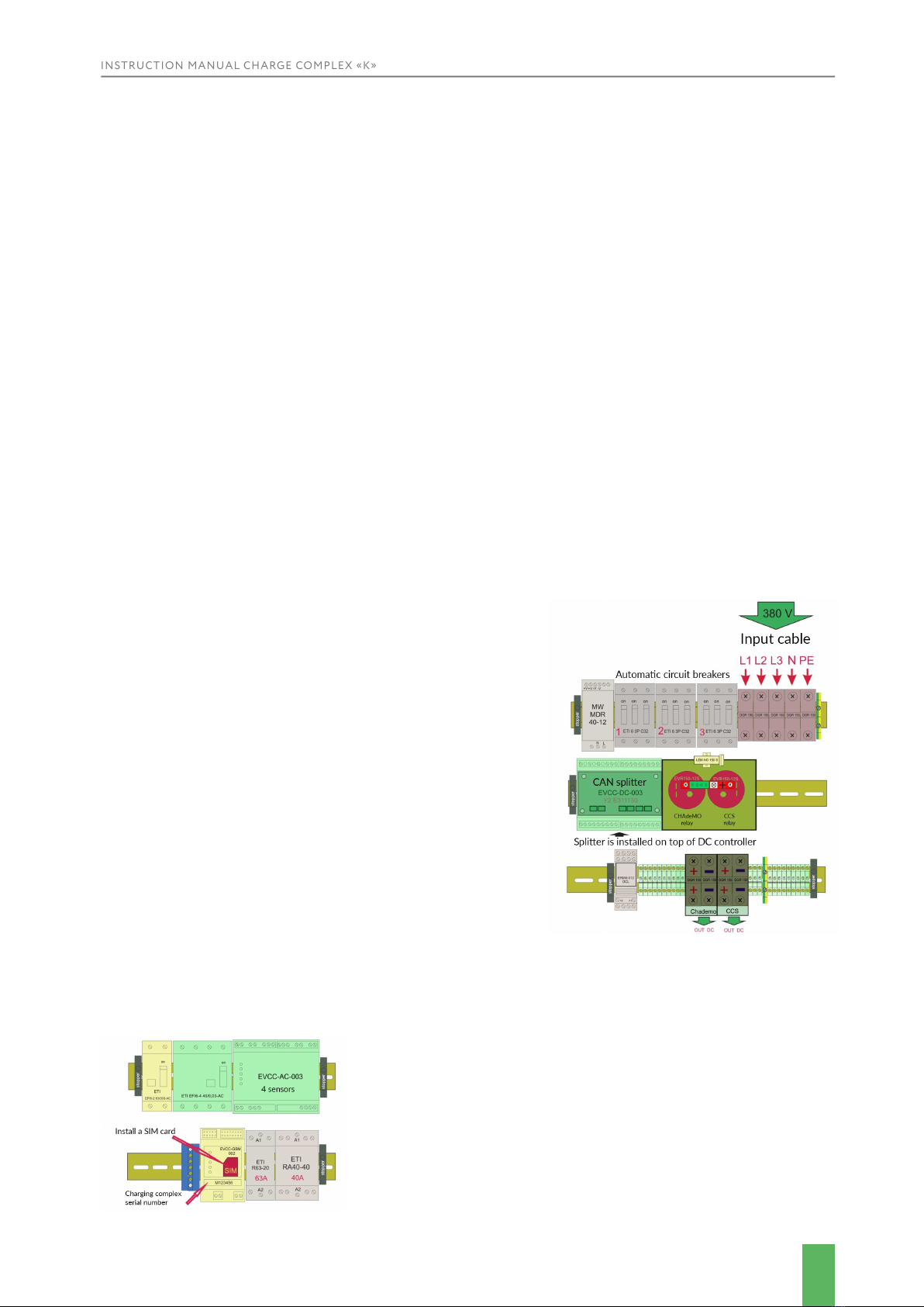
To connect the system to the electrical circuit, open the rear wall of the station (side 2),
which houses the busbars for connecting the input power cable.
Next, connect the power cable to the appropriate busbars (as shown in the scheme). If the
connection is made with a 4-wire cable, the external grounding should be done with a
wire of a cross section of at least 16 mm2 by means of a bolted connection M10 with the
inscription «PE», located in the terminal compartment. It is strictly forbidden to supply
voltage to the mains input of the charger when the grounding is not connected.
THE FIRST CONNECTION TO BE MADE IS THE
GROUND WIRE TO THE GROUND BUSBAR MARKED
«PE». DO NOT SWITCH ON THE CHARGER WITHOUT
A CONNECTED GROUNDING!
Non-compliance with this requirement may result in the energizing
the charger body, electric shock damage to the service personnel and
consumers, as well as in a failure of the charger.
If the charging complex is not equipped with inverters, it is necessary to
install and connect the DC modules recommended by the manufacturer
(video on the order of their connection is sent on request).
Then, with the help of external switching devices, it is necessary to connect
the power cable to the AC mains and then move the three-pole circuit
breakers 1, 2, 3 and 4 to the working position (up):
The operating modes of the charging complex are displayed on the LCD
display, which, among other things, displays the following information:
operating modes (ready to charge, the battery charge of the vehicle), the
software and rmware version, the number of the complex, the status of
the GSM network (signal strength, network status), vehicle authorization
process. To switch the charging complex on it is necessary to:
• Install a mobile network operator’s SIM card;
• Iurn residual current devices (RCDs) to the working
position (up);
• Move circuit breakers to working position (up).
4.4 COMPLEX CONNECTION
Ensure that all internal components are properly secured after transportation.
Check the quality of wire, loop, and connector connections. Check the tightening torque of
terminals, bolts, screws, and switchgear.
The charger does not require any special adjustment or tuning before it is put into operation.
Before you connect the charger, make sure that:
• The power supply cable on the mains side is de-energized by means of external disconnecting
devices.
• The mains supply is connected as shown in the wiring diagram: 3 phases with separate Neutral
(N) and grounding (PE) conductors
• When connecting with a 4-wire cable, carry out the protective grounding with a separate
wire.

INSTRUCTION MANUAL CHARGE COMPLEX «K»
16
The «DC Output» indicator light ashes green
frequently when the vehicle is being charged in
Chademo and CCS mode, and the LCD screen displays
information about the time passed since the charging
started, the charging current and the voltage.
The modes and text about the operation of the charging system on the LCD display depend
on the software version and may vary from version to version.
In case of any error in the charging complex, to perform
diagnostics and restore the operation, please, inform
the service center about the factory number of the
charging complex (the number of the charging complex
is shown in the pic. «M006335»).
While the vehicle charging mode is active, station
displays information about the charging time, voltage
level and current value
AutoEnterprise
#1 : Charging
#1 : Charging
#1 : Ready
V:2.02.1642
0:00:50
0:05:25
M006335
42.8A/366V
0.4 kWh
Plug in the connector
The operating modes of the charging complex are displayed on the LCD display, which,
among other things, displays the following information: operating modes (ready to
charge, the battery charge of the vehicle), the software and rmware version, the number
of the complex, the status of the GSM network (signal strength, network status), vehicle
authorization process.

INSTRUCTION MANUAL CHARGE COMPLEX «K»
17
4.5 COMPLEX STORAGE
Store the charger in a sealed container until it is assembled and installed.
Charging complex storage conditions:
• The storage area should be dry, free of dust, caustic materials, vapours and combustible materials.
• Store in a storage room with appropriate weather protection.
• Do not expose the charger to impacts.
Storage conditions:
• Storage Temperature: 0 to +40 ° C (32 to 104 ° F)
• Relative humidity: max. 85%
• Avoid extreme temperature uctuations.
• If stored for a long period of time, check the general condition of all parts and packaging
regularly.
INSTRUCTION MANUAL CHARGE COMPLEX «K»
18
ATTENTION
• Improper maintenance can result in serious injury or damage. For this
reason, maintenance may only be carried out by authorised, trained
personnel who are familiar with the product operation and strictly adhere
to all safety instructions.
• The use of explosive or ammable cleaning agents presents a risk of re or explosion.
• Do not store ammable or explosive liquids near the charging station.
ATTENTION
Before performing any kind of maintenance, make sure that the charger is
disconnected from the grid.
INFORMATION
To ensure maximum availability and service life of the system, we
recommend that you that you clean the charger on the inside on a regular
basis.
ATTENTION
Improper troubleshooting may result in serious injury or damage.
For this reason, it may only be carried out by authorized, trained
personnel who are familiar with the system operation and strictly
adhere to all safety instructions.
In the course of operation the following maintenance are carried out:
• Visual inspection for overheating of equipment; check, pulling connections;
• Identication of defective parts and assemblies, maintenance and replacement.
It is necessary to replace the lters of the complex at least once a year.
In case of increased dust in the room where the charging complex is located, it is
recommended to clean out the dust from the internal elements of the complex from
dust at least once in 6 months. This work should be performed by a representative of the
manufacturer or a qualied specialist.
Attempting to carry out maintenance independently may cause electric shock and lead to
warranty cancellation.
Internal capacitors retain their charge after the power supply is switched off.
Authorized service personnel must disconnect all AC power sources from the charger to
reduce the risk of electric shock before starting any maintenance or cleaning on the charger
or on any circuits connected to the charger.
5. MAINTENANCE
OF THE COMPLEX
INSTRUCTION MANUAL CHARGE COMPLEX «K»
19
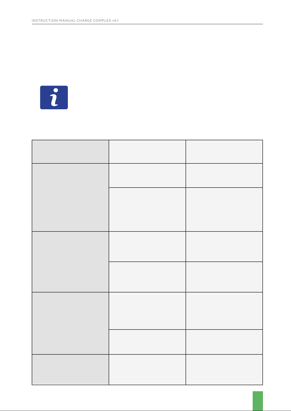
Name of malfunction,
external manifestation and
additional signs
Probable cause Possible remedy
Loss of communication with
the complex
Modem failure Replacing the modem or
checking the status of the
SIM card
Bad location of the antenna
that receives GSM signal
Changing the location of
the antenna for the best
reception of the GSM signal
or the replacement of the
antenna (for a more powerful
with a stifter)
Damage to the charging
cables
Physical wear and tear,
careless handling of
equipment
Disconnect the device. If the
cable cannot be recovered
-replace it
Connector malfunction If you can not x it by
yourself, send it for repairs
LCD charging indicator does
not work (no power supply)
No input voltage Contact the owner of the
facility where the device is
installed, and nd out the
reason for the lack of voltage
Circuit breakers or RCD
charging system triggered
Restore the operation circuit
breakers or RCDs of the
charging complex
Other malfunctions The charging complex does
not provide the set electric
parameters for the EV
battery charge
Contact the
«Autoenterprise» technical
support team
Preventive inspection of the charger should be carried out at least once every 3 months. To
do this, the charger must be disconnected from live circuits and its housing, contacts and
vents must be thoroughly cleaned of dust and dirt, and the quality of wire fastening must be
checked. Screws of terminal blocks and wire ends must be clamped, the wires must not have
damaged insulation.
In the event of a malfunction, please check the device rst. In case
of failure, write down all the data of the device (year of manufacture,
software version, etc.) and call us by phone next to the powered on
device. If you have any questions or technical problems, please contact us
directly at the above address.

INSTRUCTION MANUAL CHARGE COMPLEX «K»
20
6. DISASSEMBLY
ATTENTION
Injury may occur when disassembling the system. Therefore always wear
suitable protective clothing, safety shoes, etc.
ATTENTION
The system must be disconnected from the power supply by means of
external disconnection devices.
IN SEQUENCE
1. Make sure that the input voltage of the charger is disconnected.
2. Carry out disassembly work.
INFORMATION
Always use suitable tools to disassemble the complex.
Follow the specic disposal instructions
TECH SUPPORT
Contacts:
1. You can write an email to tech support using the contact page on our web-site.
2. You can call on numbers listed on the web-site.
AUTOENTERPRISE.UA
This manual suits for next models
3
Table of contents
Other Autoenterprise Batteries Charger manuals

Autoenterprise
Autoenterprise Single User manual

Autoenterprise
Autoenterprise Travel Charger User manual

Autoenterprise
Autoenterprise I-STATION User manual

Autoenterprise
Autoenterprise I-STATION User manual

Autoenterprise
Autoenterprise EDISON User manual

Autoenterprise
Autoenterprise WALL COMPLEX User manual


