Autoenterprise WALL COMPLEX User manual
CHARGING STATION
«WALL COMPLEX»
User manual

USER MANUAL WALL COMPLEX
2
© Copyright
This documentation with all illustrations is the intellectual property of PC "AE FACTORY". All
documentation is provided to the user for personal use only. This documentation may not be
reproduced or provided to others without our written permission. Any violation of the law will
be prosecuted.
Read the user manual (Manual) carefully before using the product. All
information, illustrations, tables, specifications and diagrams contained in these
Manual were carefully compiled at the time of publication. Under no
circumstances will compliance with the information in this Manual relieve the
user of his responsibility to comply with all applicable codes, safety standards or
wiring regulation. The developer cannot be held liable for any direct or indirect
damages resulting from the use or operation of the electrical circuits of the
equipment or software described herein.
The software is developed and installed exclusively for the operation of the station. The user
is strictly prohibited from making any changes, transformations or copying the software.
The developer reserves the right to make any changes in the Manual at any time without prior
notice.

USER MANUAL WALL COMPLEX
3
CONTENTS
IMPORTANT SAFETY INSTRUCTIONS....................................................................................................... 4
1. GENERAL INFORMATION............................................................................................................................. 6
1.1 INTRODUCTION........................................................................................................................................... 6
1.2 FUNCTIONAL POSSIBILITIES................................................................................................................ 6
1.3 TECHNICAL CHARACTERISTICS ..........................................................................................................7
1.4 CONNECTORS CHARACTERISTICS ...................................................................................................8
1.5 CHARGING COMPLEX MODIFICATIONS......................................................................................10
2 PACKAGE................................................................................................................................................................ 11
3 MARKING ...............................................................................................................................................................12
4 INSTALLATION...................................................................................................................................................12
4.1 OPERATING LIMITATIONS ...................................................................................................................12
4.2 COMPLEX INSTALLATION....................................................................................................................13
4.3 STATION CONNECTING........................................................................................................................16
5 OPERATION......................................................................................................................................................... 18
5.1 OPERATING MODES AND ELECTRIC VEHICLE CHARGING PROCESS......................... 18
5.2 CONNECTING THE VEHICLE...............................................................................................................19
5.3 SAFETY MEASURE.....................................................................................................................................20
6 MAINTENANCE..................................................................................................................................................20
7 TROUBLESHOOTING......................................................................................................................................22
8 STORAGE...............................................................................................................................................................22
9 TRANSPORTATION.........................................................................................................................................23
10 DISPOSAL............................................................................................................................................................23
11 FAT CERTIFICATE.............................................................................................................................................23
11.1 ADDRESS OF MANUFACTURER:......................................................................................................24
12 LIMITED PRODUCT WARRANTY ...........................................................................................................24

USER MANUAL WALL COMPLEX
4
IMPORTANT SAFETY INSTRUCTIONS
This operating manual includes the necessary sections of technical characteristics,
maintenance rules, as well as safety instructions and recommendations for the operation of the
station.
Before starting work, it is necessary to carefully study all the rules and recommendations given
in the instructions, and observe them during operation. This will ensure reliable operation of
the product and its safety in use.
Work with the charging complex, observe the safety recommendations in this manual, as well
as the applicable local safety regulations and general safety regulations.
Before starting any work with the charging complex, make sure that the instructions, in
particular the Safety section and the corresponding safety instructions, have been fully read by
the personnel and fully understood.
Important safety instructions in this manual are indicated by symbols. These safety instructions
must be strictly followed. You should always pay attention to them and follow the safety
requirements to avoid accidents, personal injury or property damage.
WARNING!
Risk of injury or death.
This symbol indicates instructions that must be followed to avoid injury, trauma
or death.
ATTENTION!
Risk of material damage.
This symbol indicates instructions which, if not followed, may result in material
damage, functional faults and/or breakdown of the complex or the vehicle
connected to it.
WARNING!
Danger - electrical current.
This symbol alerts you to potentially dangerous situations involving electric
current. Failure to follow the safety instructions increases the risk of serious
injury or death. Caution should be exercised, especially during maintenance and
repairs.
ATTENTION!
This symbol indicates tips and information that should be adhered to in order to
ensure efficient and reliable operation of the product.

USER MANUAL WALL COMPLEX
5
Strict adherence to the safety procedures described in these operating instructions and special
care when using the equipment are essential to prevent and reduce the likelihood of injury or
damage to the equipment.
The manufacturer is not responsible for any direct or indirect damages resulting from the use
or work with the electrical circuits of the equipment or software described in this manual.
The manufacturer is not responsible for damage and/or malfunctions caused by non-
compliance with the instructions in this manual.
The manufacturer will not be liable for any personal injury or material damage, whether indirect
or special, consequential, loss of business profits, business interruption or loss of business
information resulting from the use of the equipment described in this manual.
In connection with non-stop improvements, the Developer reserves the right to make changes
to the construction of the equipment described in this manual without prior notice.

USER MANUAL WALL COMPLEX
6
1. GENERAL INFORMATION
1.1 INTRODUCTION
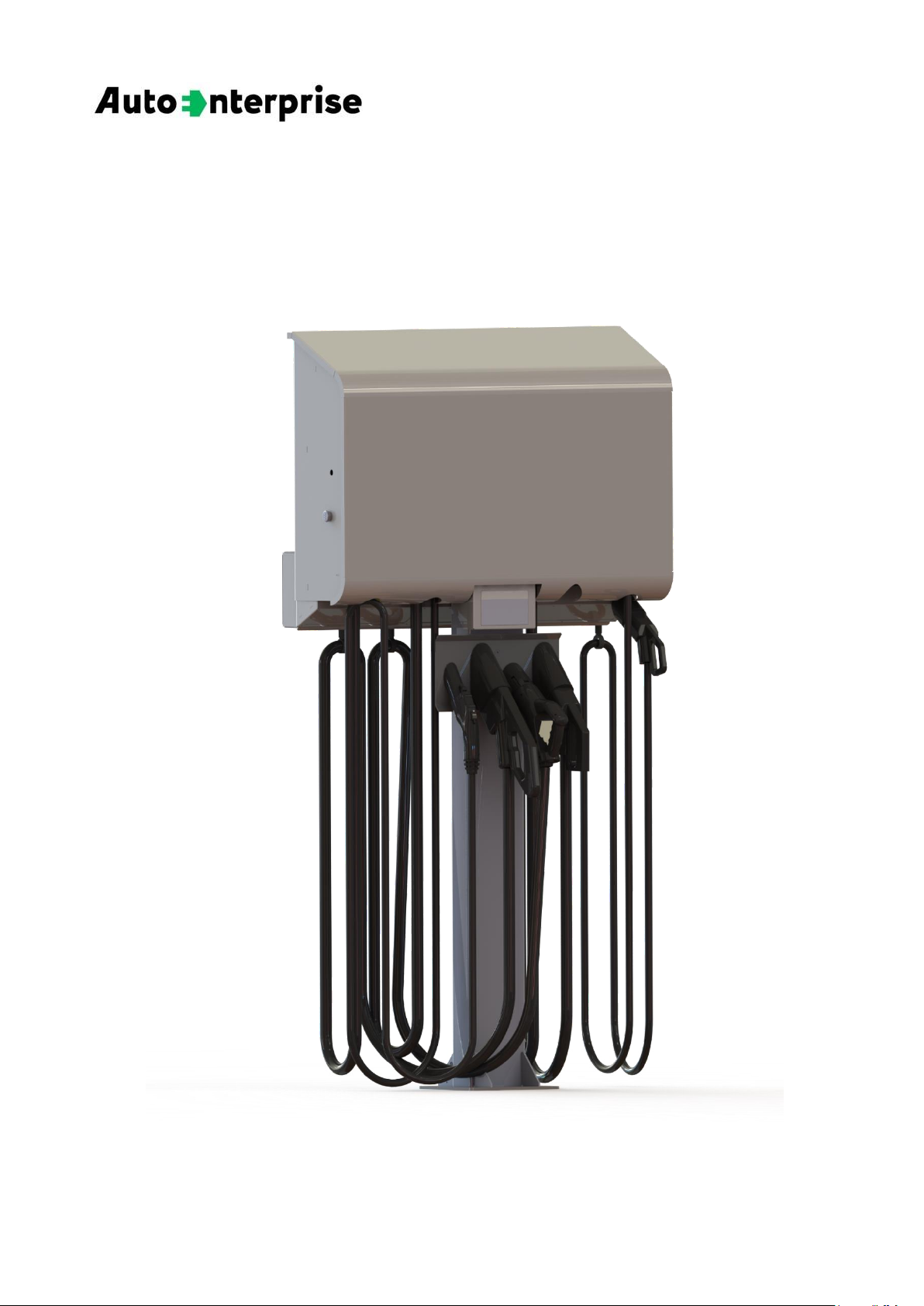
WALL COMPLEX –is a charging station (charging complex) designed for safe and efficient
charging of electric vehicles in the specially equipped places (car parks, offices, shopping malls,
etc.). It can be installed indoors or outdoors. The charging complex (depending on the
configuration) can simultaneously AC charging up from one to three electric vehicles and DC
charging up from one to three electric vehicle (total amount of EV is four).
The charging station is equipped with an intellectual control system that handles
communication between the station and the electric vehicle. The control and protection
functions operate continuously in the system.
The station is available in several modifications. All modifications are equipped with from one
to five fixed cables with Type 1 / Type 2 / CHAdeMO / CCS Type 1 / CCS Type 2 / GB/T AC /
GB/T DC connectors in various combinations.
1.2 FUNCTIONAL POSSIBILITIES
Mount
Wall / Pedestal
Online monitoring of device operation
+
Possibility to adjust the charge current
+
Possibility to set the tariff
+
Single body execution
+
Electricity consumption indication
+
User interface management
Menu functions are controlled via the app
Emergency stop button
+
Power cable entry
Bottom
Enclosure material
Steel with anticorrosive coating
USER MANUAL WALL COMPLEX
7
1.3 TECHNICAL CHARACTERISTICS
Charging mode according to IEC 61851-1
Mode 3, Mode 4
Nominal input voltage
400 V ± 10%, 3 ph (TN-S)
Nominal frequency
50 / 60 ± 0,2 Hz
Maximum station power
30 kW –225 kW
Display
•LED- display (20×2 symbols)
•LED- display 7(optional)
Charging station options
RFID- card (IEC 14443-1);
Smartphone app;
Chip-tag (extra option)
Mechanical protection
IK10
Case protection class
IP54
Operating temperature
от - 35 °C до + 50 °C
Relative humidity
no more than 95% without moisture
condensation
Mass, kg
240
Charging station dimensions (H×W×D), mm
1065×1063×311
Dimensions with pedestal (H×W×D), mm
2126×1063×630
Communication and protocols
2G
GSM GPRS Class 12,
Quad-band: 850 / 900 / 1800 / 1900MГц
3G/4G (LTE)
LTE Cat 1,
LTE-FDD: B1/B3/B7/B8/B20/B28A;
GSM: B3/B8
RFID
ISO 14443 (A) (Mifare)
Ethernet
IEEE 802.3
Wi-Fi
802.11 a/b/g/n
OCPP
OCPP 1.6

USER MANUAL WALL COMPLEX
8
1.4 CONNECTORS CHARACTERISTICS
Charging connector
Type 1 (SAE-J1772)
Maximum power per socket
9,2 kW
18,4 kW
Maximum current per socket
40 A
80 A
Maximum socket voltage
230 V
Cable length
6,5 m
Charging connector
Type 2 (Mennekes)
Maximum power per socket
22 kW
43 kW
Maximum current per socket
3×32 A
3×63 A
Maximum socket voltage
400 V
Cable length
6,5 m
Charging connector
CHAdeMO
Maximum power per socket
100 kW
Maximum current per socket
200 A
Maximum socket voltage
500 V
Cable length
5,5 m

USER MANUAL WALL COMPLEX
9
Charging connector
CCS (Type 1)
Maximum power per socket
100 kW
300 kW
Maximum current per socket
200 A
300 A
Maximum socket voltage
500 V
1000 V
Cable length
5,5 m
Charging connector
CCS (Type 2)
Maximum power per socket
100 kW
300 kW
Maximum current per socket
200 A
300 A
Maximum socket voltage
500 V
1000 V
Cable length
5,5 m
Charging connector
GB/T AC
Maximum power per socket
22 kW
43 kW
Maximum current per socket
3×32 A
3×63 A
Maximum socket voltage
400 V
Cable length
6,5 m
Charging connector
GB/T DC
Maximum power per socket
100 kW
187,5 kW
Maximum current per socket
200 A
250 A
Maximum socket voltage
500 V
750 V
Cable length
5,5 m
USER MANUAL WALL COMPLEX
10
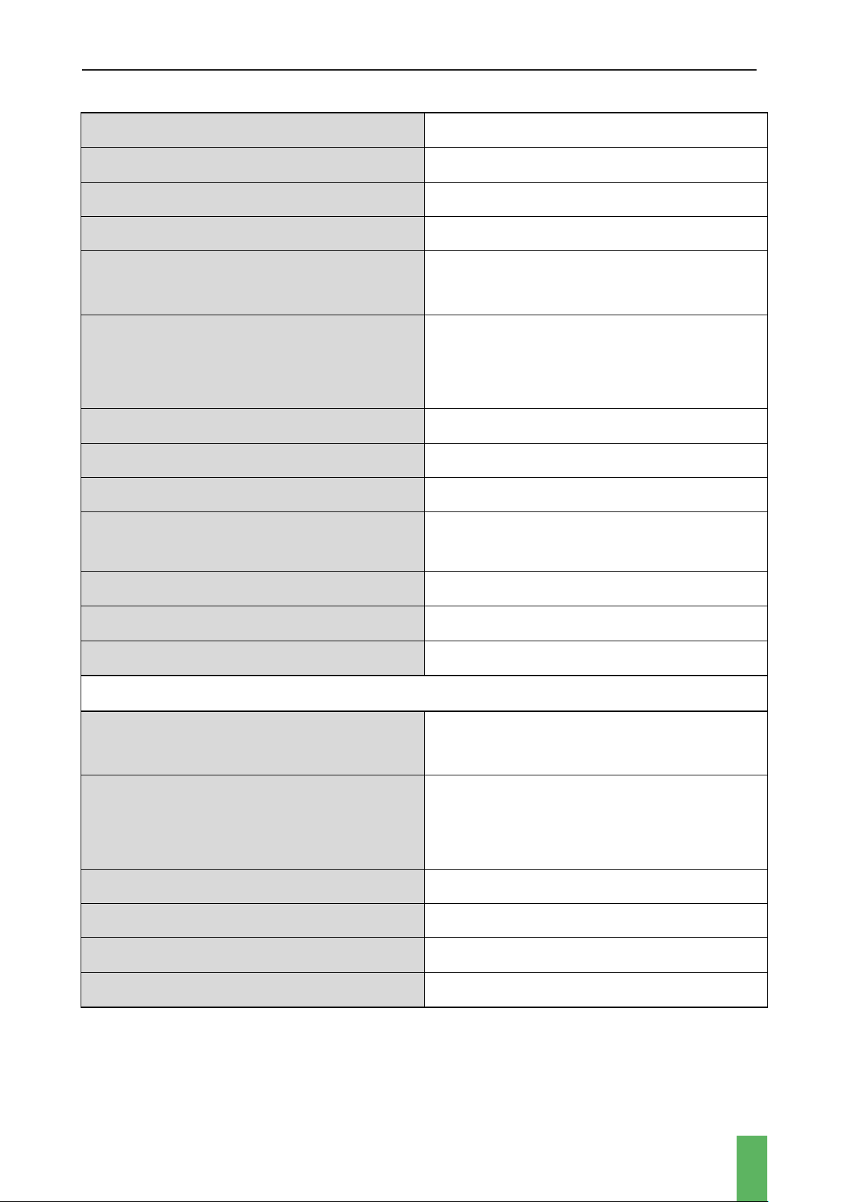
1.5 CHARGING COMPLEX MODIFICATIONS
The charging complex is available in various configurations, which are formed depending on
the availability of connectors and the power of the DC-part of the station (30-60-90-120 kW).
The power value of the charging station, depending on the configuration, is determined
according to table 1.
Table 1. Charging station power
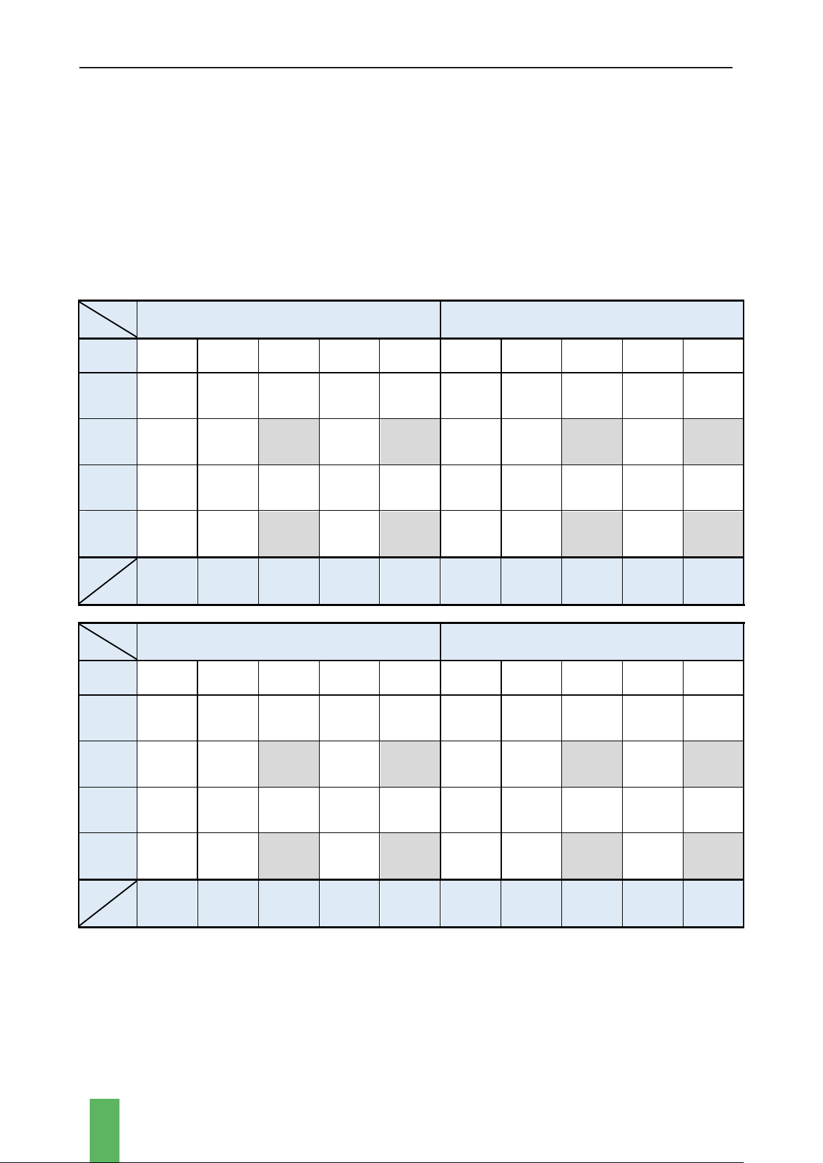
PDC
PType1
PDC = 30 kW
PDC = 60 kW
No Type1
30
52
74
73
116
60
82
104
103
146
1xType1
(9,2 kW)
39,2
61,2
83,2
82,2
125,2
69,2
91,2
113
112
155
2xType1
(18,4 kW)
48,4
70,4
—
91,4
—
78,4
100,4
—
121
—
1xType1
(18,4 kW)
48,4
70,4
92,4
91,4
134,4
78,4
100,4
123
122
165
2xType1
(36,8 kW)
66,8
88,8
—
109,8
—
96,8
118,8
—
139,8
—
PType1
PType2
No Type2
1xType2
(22 kW)
2xType2
(44 kW)
1xType2
(43 kW)
2xType2
(86 kW)
Type2
отсутствует
1xType2
(22 kW)
2xType2
(44 kW)
1xType2
(43 kW)
2xType2
(86 kW)
PDC
PType1
PDC = 90 kW
PDC = 120 kW
No Type1
90
112
134
133
176
120
142
164
163
206
1xType1
(9,2 kW)
99,2
121,2
143,2
142,2
185,2
129,2
151,2
173,2
172,2
215,2
2xType1
(18,4 kW)
108,4
130,4
—
151,4
—
138,4
160,4
—
181,4
—
1xType1
(18,4 kW)
108,4
130,4
152,4
151,4
194,4
138,4
160,4
182,4
181,4
224,4
2xType1
(36,8 kW)
126,8
148,8
—
169,8
—
156,8
178,8
—
199,8
—
PType1
PType2
No Type2
1xType2
(22 kW)
2xType2
(44 kW)
1xType2
(43 kW)
2xType2
(86 kW)
Type2
отсутствует
1xType2
(22 kW)
2xType2
(44 kW)
1xType2
(43 kW)
2xType2
(86 kW)
USER MANUAL WALL COMPLEX
11
2 PACKAGE
EV charging station Wall Complex can be supplied in various package, depending on the
installation method.
Wall mounting
EV charging station Wall Complex
1
User manual
1
Mounting bracket
1
Anchor screw M8
4
Pedestal mounting
EV charging station Wall Complex with pedestal
1
User manual
1
Inserts
1
Nut M16
4
Washer 16
4
Additional accessories
Cable pull-up unit (tensioner)
2
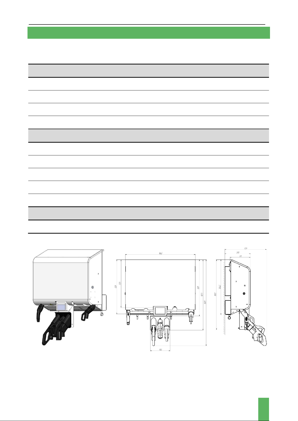
Figure 1а. Station external view and station dimensions for wall mounting

USER MANUAL WALL COMPLEX
12
Figure 1b. Station external view and station dimensions for pedestal mounting
The station can be branded if it is specified in the contract with the customer.
3 MARKING
The nameplate is located on the left side of the charging station enclosure. The nameplate
specifies information such as the model, serial number and basic technical specifications.
4 INSTALLATION
4.1 OPERATING LIMITATIONS
The charging station is designed exclusively for charging electric vehicles.
Charging only compatible electric vehicles.
Failure to comply with the requirements for operation, maintenance and repair,
described in this manual, excludes any liability of the manufacturer in the event
of malfunctions in the operation of the complex.
The installation altitude of the charging complex above sea level should not exceed 2000 m.
USER MANUAL WALL COMPLEX
13
Follow the safety regulations to avoid injury and material damage when working with the
complex.
Before the station installation, you should review this manual carefully and consult with a
licensed electrician, contractor, and trained installation expert to insure compliance with local
building codes, safety standards and wiring regulations.
4.2 COMPLEX INSTALLATION
Make sure the installation site has adequate GSM or 4G (LTE) cellular coverage. Cellular
repeaters may be required to ensure good signal strength in underground garages or other
enclosed parking lots.
It is recommended to place the complex under
a canopy to protect it from direct exposure to
atmospheric precipitation and sunlight.
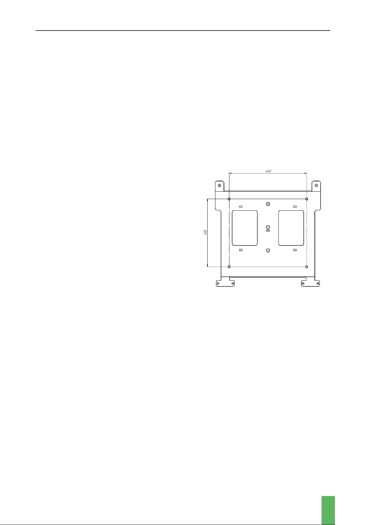
For wall-mounted charging stations, a place
must be prepared for attaching the bracket.
When choosing the location of the station, keep
in mind that there must be a distance of at least
1 meter to the left and right of the station body
to any obstacle. The holes for the anchor screws
should be positioned as shown in Figure 2.
For pedestal-mounted charging stations,
prepare the installation site in advance by
following the instructions below.
Figure 2. Mounting bracket
When choosing a location for the charging complex, the following conditions must be met:
there must be a distance of at least 1 meter between the charging complex body and a wall or
any obstacle. There should be enough free space for maintenance in front and behind the
enclosure.
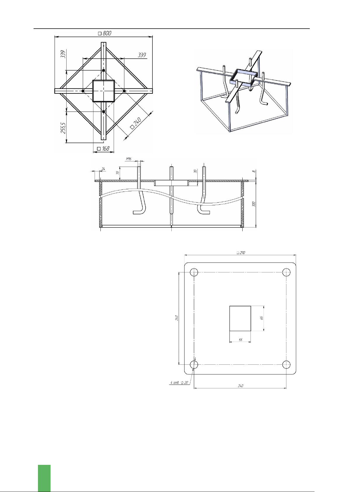
Complex is installed on a foundation (prepared concrete base) measuring 1300x1300x500 mm.
There should be no underground cables or pipes in the area around the foundation..
The foundation is pouredinto a well-rammed base with a pre-laid cable duct and a placed metal
insert. For the base, it is necessary to use a mixture of crushed stone with cement at least M400.
The surface of the foundation must be carefully leveled to avoid distortion of the station during
installation.
USER MANUAL WALL COMPLEX
14
Figure 3. Inserts external view and inserts dimensions
The dimensions of the pedestal base
are shown in Figure 4, the plate
thickness is 8 mm.
Along with the preparation of the
foundation, it is necessary to ensure
the laying of an electric power cable
(not included in the delivery set). The
required cable length above the
foundation is at least 2.5 meters.
Figure 4. Pedestal base (bottom view)
USER MANUAL WALL COMPLEX
15
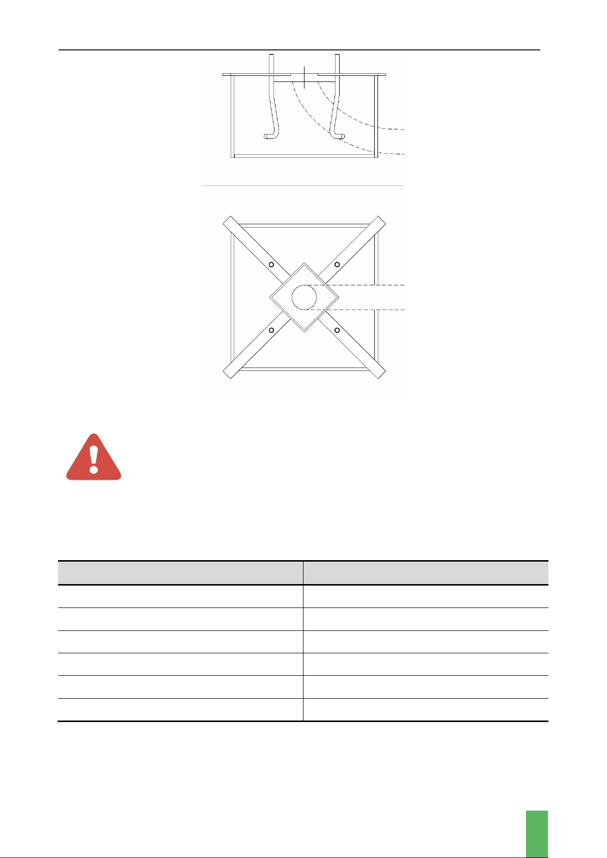
Figure 5. Station foundation
WARNING!
Only qualified personnel should connect the power cable to the AC mains.
It is recommended to select the cross-section of the power cable based on the power of the
station (copper stranded conductor with a cross-section of 5×50 mm2to 5×95 mm2).
Table 2. Recommended cross-section of power cable
Charging station power, kW
Cross-section of power cable, mm2
<75
5×16
75-98
5×25
98-118
5×35
118-148
5×50
148-181
5×70
181-225
5×95
It is necessary to install an AC circuit breaker between the station and the power supply
network when the power cable laying. It is recommended to use a 3-pole circuit breaker in the
range from 120 A to 350 A (depending on the station power).
USER MANUAL WALL COMPLEX
16
4.3 STATION CONNECTING
After transporting the charging complex, before installation, make sure that all internal
elements are properly fixed and there are no mechanical damages.
Check the quality of wire, loop, and connector connections. Check the tightening torque of
terminals, bolts, screws, and switchgear.
The charger does not require any special adjustment or tuning before it is put into operation.
Before you connect the charger, make sure that:
•The power supply cable on the mains side is de-energized by means of external
disconnecting devices.
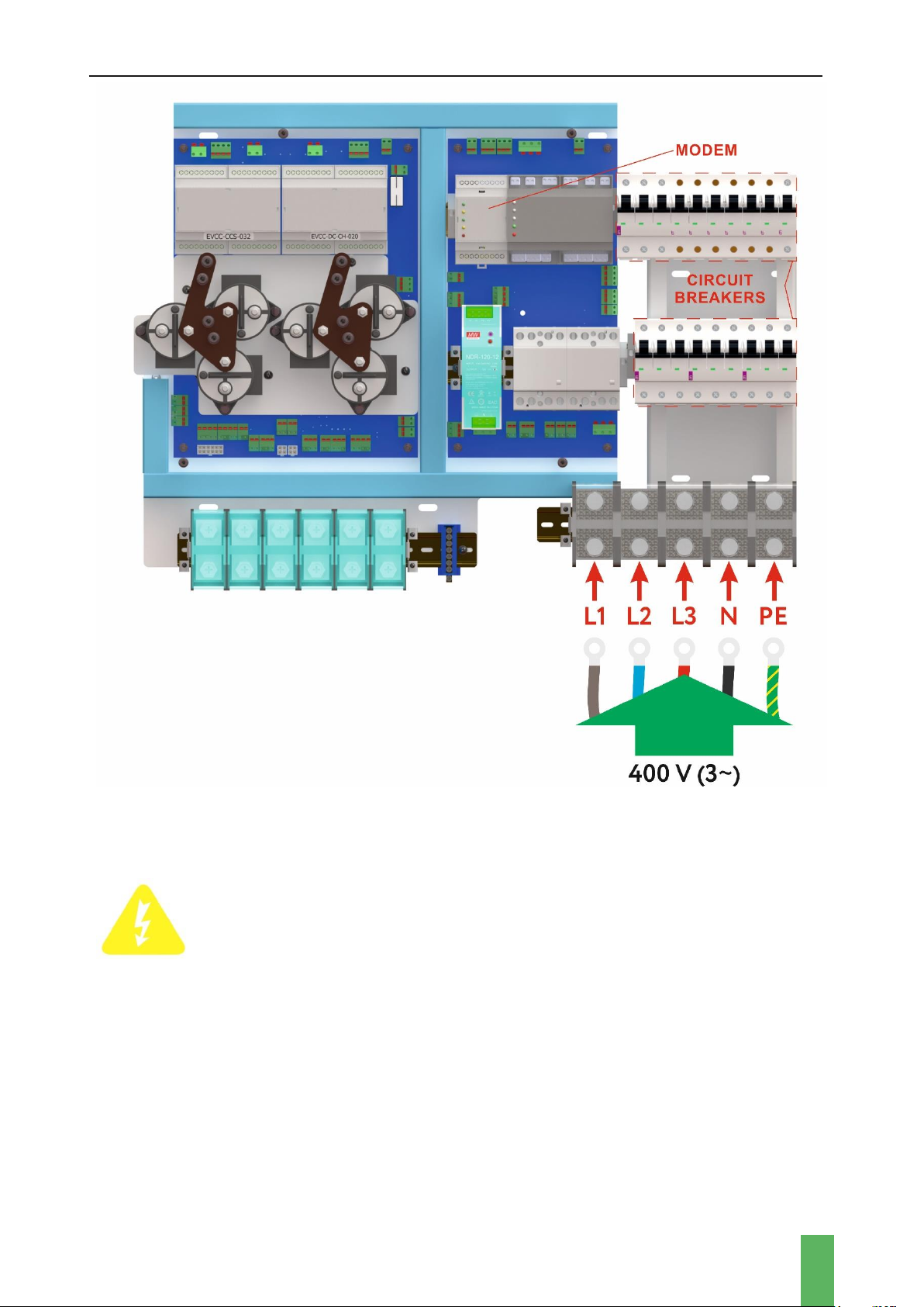
•The mains supply is connected as shown in the wiring diagram: 3 phases with separate
Neutral (N) and grounding (PE) conductors
•When connecting with a 4-wire cable, carry out the protective grounding with a separate
wire.
To connect the complex to the electric circuit, it is necessary to open the cover of the charging
station and lead the power cable through the cable entry channel to the internal part of the
station.
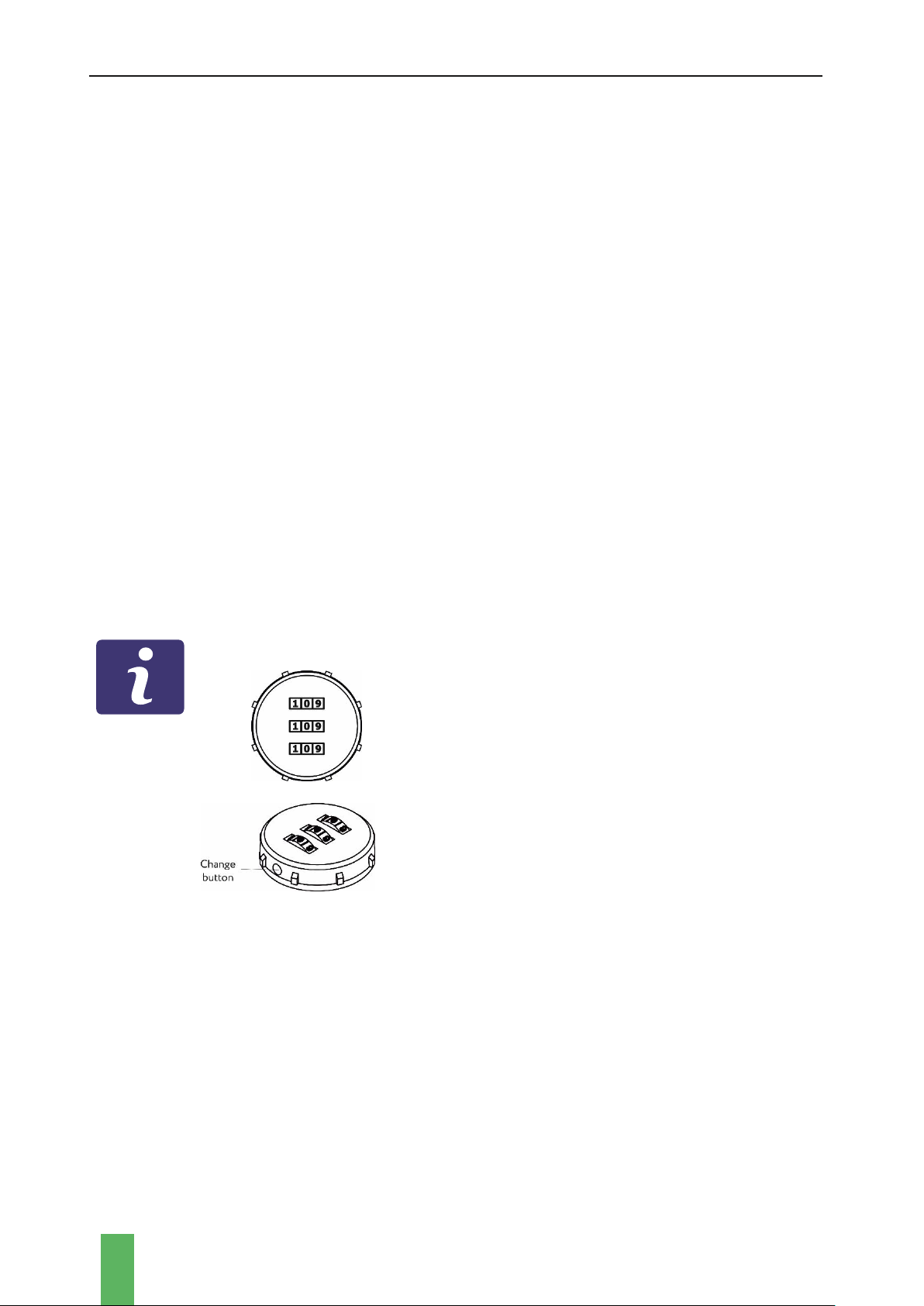
ATTENTION!
A combination lock is used. The default lock code is
“000”.
On the underside outer edge of the lock there is
hole for the code reset button. Rotate the face of
cam until the code reset button comes into view.
Push this pin in with a paper clip and keep it pushed
in.
Set your personal combination tuming the dials to
the desired combination.
Release the reset button and your combination is
set.
Next, you need to connect the power supply cable to the appropriate input busbars (as shown
in pic. 6). When connecting with a 4-wire cable, the external grounding should be done with a
wire of a cross section of at least 25 mm2by means of a bolted connection M10 with the
inscription «PE», located in the terminal compartment.
USER MANUAL WALL COMPLEX
17
Figure 6.
ATTENTION!
THE FIRST CONNECTION THAT MUST BE MADE IS THE GROUND WIRE
TO THE GROUND BUSBAR MARKED «PE».
DO NOT SWITCH ON THE CHARGER WITHOUT A CONNECTED
GROUNDING!
Non-compliance with this requirement may result in energizing the charger body, electric
shock damage to the service personnel and consumers, as well as in a failure of the charger.
Then, with the help of external switching devices, it is necessary to connect the power cable to
the AC mains and then move the three-pole circuit breakers to the working position.
To switch the charging complex on it is necessary to:
•Install mobile operator’s SIM-card (if an external SIM-card is used):
USER MANUAL WALL COMPLEX
18
-remove the modem cover;
-install SIM-card;
-close the modem cover.
•Move the circuit breakers to the operating position (up).
•Move the circuit breaker on the switch board to the operating position (up).
5 OPERATION
5.1 OPERATING MODES AND ELECTRIC VEHICLE CHARGING PROCESS
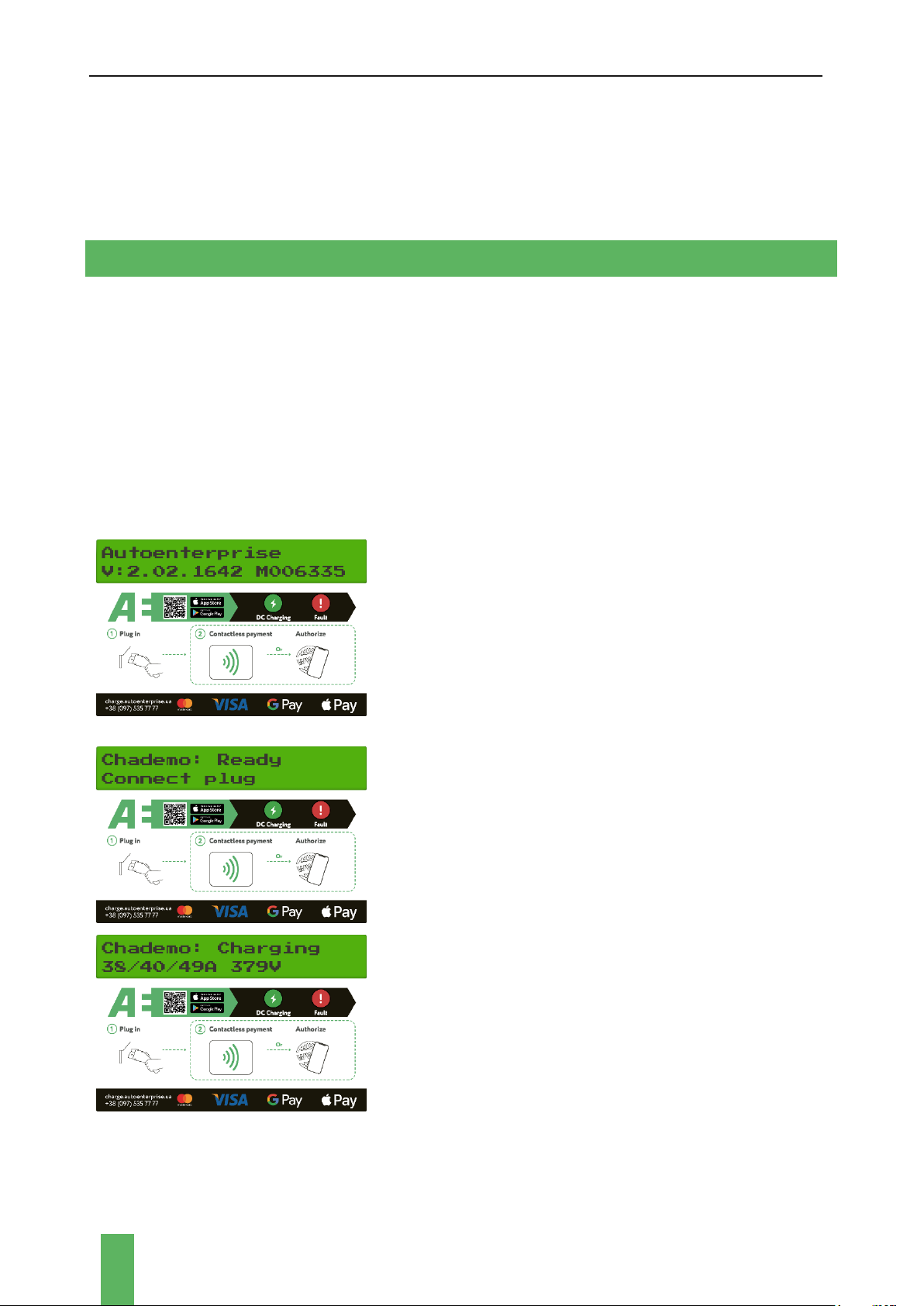
Information about the operating modes of the charging complex (the state of the connectors
and the charging parameters) are displayed on the display. Also, the display shows data about
software versions, modem number, station number in Autoenterprise billing, mobile network
status, etc.
The information shown on the display depends on the software version and may differ from
version to version.
After the supply voltage is applied, the station display
shows information about the software version and the
serial number of the modem.
In case of malfunctions in the operation of the charging
complex, you must inform the serial number of the
modem to the service center for diagnostics and
restoration of work.
In standby mode, the display shows information about the
status of the connectors.
In car charging mode, the LCD display shows information
about charging time, voltage level and current amperage.

USER MANUAL WALL COMPLEX
19
The "DC Output" indicator flashes green quickly when
the car is charging in DC Mode “CHAdeMO” / ”CCS” /
“GB/T DC”. In this case the LCD display shows
information about charging parameters.
5.2 CONNECTING THE VEHICLE
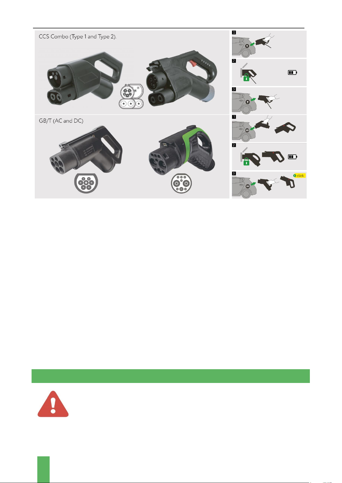
USER MANUAL WALL COMPLEX
20
5.3 SAFETY MEASURE
In emergency situations, the charging complex disconnects the input power circuits using
differential relays.
The control system of the charging complex is powered from the mains through an additional
circuit breaker.
The output cable is connected via cable sleeve / cable glands.
On the bottom panel of the complex there is an emergency shutdown button in the DC
charging mode.
When the emergency stop button is pressed in DC charging mode, the electrical circuit that
powers the vehicle's battery is automatically disconnected. The message “EMO PRESSED”
appears on the display.
To continue the operation of the complex, the emergency stop button must be manually
returned to its original state (turn the button counterclockwise).
6 MAINTENANCE
WARNING!
Improper maintenance can result in serious injury or equipment damage.
Charging station can be maintained and repaired by qualified personnel only.
Table of contents
Other Autoenterprise Batteries Charger manuals

Autoenterprise
Autoenterprise Travel Charger User manual

Autoenterprise
Autoenterprise CHARGE COMPLEX K Series User manual

Autoenterprise
Autoenterprise EDISON User manual

Autoenterprise
Autoenterprise I-STATION User manual

Autoenterprise
Autoenterprise I-STATION User manual

Autoenterprise
Autoenterprise Single User manual


