Gallagher APOLLO 3000L Guide

Part No. 2A03229
Issue 1
APOLLO 3000L
Installation and Commissioning Manual

Gallagher Fuel Systems Ltd
2 Station Rd
PO Box 308
Marton 4741
New Zealand
Phone: +64 6 327 0060
Fax: +64 6 327 6724
Emails: support@fuel-systems.gallagher.co
som@fuel-systems.gallagher.co
Web: http://fuelsystems.gallagher.co
When contacting Gallagher Fuel Systems Ltd always quote the serial number on the
product’s nameplate which can be found affixed to the column beneath the User Interface.
How to Contact Gallagher
The Wiring Regulations
All wiring and installation work shall comply with AS/NZS 3000
Each Fuel Delivery System (FDS) should be protected by a 16 amp circuit breaker that is
capable of being locked off.
When designing the site, cable selections should comply with AS/NZS 3008.1 for Australia
and AS/NZS 3008.2 for New Zealand.
When terminating external cables in the FDS crimp joints should be used and should
comply with AS/NZS 3000.
If the FDS is to be installed at a Marina then all wiring shall be performed in compliance
with AS/NZS 3004
Document History
Issue Date Comments Author(s)
1. Nov 2014 Inial Release E. Schaub
2.
3.
Copyright © Gallagher Fuel Systems Ltd 2014
All rights reserved. This manual may not be copied or reproduced in part or whole by any means
without the prior written consent of Gallagher Fuel Systems Ltd.
The information in this manual is subject to change without notice. Gallagher Fuel Systems Ltd has
made every effort to verify the accuracy of this manual but does not make any other representation,
warranty or guarantee that the information is accurate, correct, reliable or current.
2A03229 APOLLO 3000L Installaon and Commissioning Manual Issue 1
2

CONTENTS
1 APOLLO 3000L INSTALLATION ......................................................... 7
1.1 Underground Sump Enclosure Installation. ................................. 7
1.2 Vertical Delivery Pipe Assembly Installation................................11
1.3 Module Installation.................................................................... 18
1.4 Apollo 3000L Electronics Installation......................................... 21
2 APOLLO 3000L VR2 COMPONENTS INSTALLATION....................... 25
2.1 Installation Procedure Overview................................................ 25
2.2 Hydraulic Installation................................................................. 28
2.3 Vapour Sensor Assembly .......................................................... 30
2.4 Connecting to the Underground Return Pipework ...................... 34
2.5 Electrical Installation................................................................. 35
3 APOLLO 3000L COMMISSIONING.................................................... 37
3.1 Safety Inspection...................................................................... 37
3.2 Dispenser Configuration and Setup........................................... 37
3.3 Tatsuno Meter Calibration ......................................................... 47
3
2A03229 APOLLO 3000L Installaon and Commissioning Manual Issue 1

LIST OF FIGURES
Figure 1. Apollo 3000L Components .........................................................................................7
Figure 2. Underground Sump Enclosure Components...............................................................7
Figure 3. Apollo Underground Sump Front View........................................................................8
Figure 4. Main Product Feed Line Configuration .......................................................................9
Figure 5. Typical Feed Line Assembly.......................................................................................9
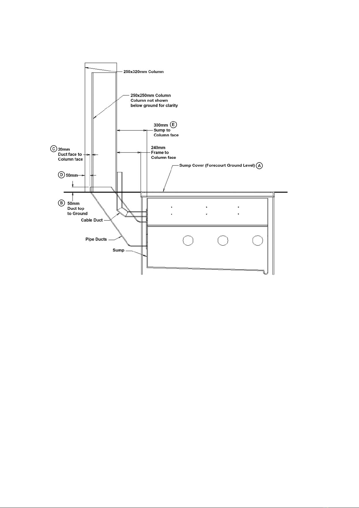
Figure 6. Apollo Sump/Column Position Top View...................................................................10
Figure 7. Vertical Delivery Pipes Assembly Components......................................................... 11
Figure 8. Vertical Delivery Pipes Assembly Mounting Positions...............................................12
Figure 9. Delivery Pipes Assembly Part Numbers....................................................................14
Figure 10. Head Cabinet Mounting Brackets.............................................................................15
Figure 11. Vent Box Position and Sealing Specifications...........................................................16
Figure 12. Safety Hose Position................................................................................................17
Figure 13. External Hose Positions...........................................................................................17
Figure 14. Apollo Sump and Modules Assembly........................................................................ 18
Figure 15. Product Delivery Hoses Connection.........................................................................19
Figure 16. Float Switch Assembly Installation............................................................................19
Figure 17. Solenoid Valves Cable Distribution...........................................................................20
Figure 18. Wiring Guide Decal..................................................................................................20
Figure 19. Apollo 3000L Electronic Set .....................................................................................21
Figure 20. Setting of Protocol Jumpers for PEC and Gilbarco Protocols....................................22
Figure 21. Comms Connections................................................................................................22
Figure 22. Motor Drive Module Connection Guide.....................................................................23
Figure 23. Solenoid Valves Connection Guide...........................................................................23
Figure 24. Multiplexer Module Connection Guide......................................................................24
Figure 25. Internal Comparison of Apollo 3000L Standard and VR2 ..........................................26
Figure 26. VR2 Nozzles............................................................................................................27
Figure 27. Coaxial Adaptor........................................................................................................27
Figure 28. Coaxial Adaptors and Splitter Bracket ...................................................................... 28
Figure 29. Fitting of Bracket and Backing Plate to Soffit Panel.................................................. 28
Figure 30. Soffit Panel, Splitter Bracket and Hoses in Place......................................................29
Figure 31. Splitter Bracket Cover in Place.................................................................................29
Figure 32. Complete Vapour Sensor Assembly..........................................................................33
Figure 33. Example Vapour Return Line Connection .................................................................34
Figure 34. VR Modules Connections......................................................................................... 35
Figure 35. Connections into the Bürkert Valve Controller........................................................... 35
Figure 36. Phoenix Connector for Vapour Sensor Cables..........................................................36
Figure 37. Phoenix Connectors on the Fafnir Unit.....................................................................36
Figure 38. Service Mode Function Screens............................................................................... 38
Figure 39. Adjustment Wheel....................................................................................................47
2A03229 APOLLO 3000L Installaon and Commissioning Manual Issue 1
4

Definitions
Comms Communicaon
ESD Electro-Static Discharge
GRP Glass Reinforced Plastic
VMS Vapour Management System
VR Vapour Recovery
Pump Fuel delivery unit where the pump is located within the unit itself.
Dispenser Fuel delivery unit where the remotely controlled pump is located in the
underground tank and not within the delivery unit.
Fuel Delivery
System
(FDS)
Self-contained system containing equipment for delivering fuel to a
customer. May contain one or more modules based on mechanical pumps,
dispensers or a combination of both. Does not include any connected
remote fuel storage and pumping facilities.
Intrinsic
Safety
Protection technique for the safe operation of electronic equipment in
explosive atmospheres. The theory behind intrinsic safety is to ensure that
the available electrical and thermal energy in the system is always low
enough that ignition of the hazardous atmosphere cannot occur. This is
achieved by ensuring that only low voltages enter the hazardous area, and
that electric supply and signal wires are protected by safety barriers.
ABOUT THIS MANUAL
This manual describes the installation and commissioning procedure for the Apollo
3000L Fuel Delivery System. This manual is divided into three sections:
• General installation;
• VR2 components installation;
• Commissioning.
This manual does not include the cladding installation, as it is not supplied by Gallagher
Fuel Systems.
5
2A03229 APOLLO 3000L Installaon and Commissioning Manual Issue 1

Symbols
INFORMATION
Highlights subject areas that should clarify understanding or provides tips
or hints that should assist users and/or technicians.
WARNING
Theassociatedtexthighlightsasubjectareainwhichdamagetoequipment
may result if procedures are not carried out correctly.
General Safety Warnings and Precautions
yInstallation must only be carried out by suitably qualified and competent personnel.
yInitial electrical power-up and opening of fuel supply lines must only be carried
out after inspection and approval by suitably qualified and competent personnel.
yNo naked flames.
yAll personnel working with Fuel Delivery Systems must be made aware of how, in
an emergency, to turn OFF power to the FDS and any remote fuel storage system.
They must also be briefed on fire fighting and other relevant inflammable liquid
safety procedures.
yEnsure fuel pipes, flanges etc. are clear of debris before assembling.
yFuels present a toxic hazard and suitable precautions should be taken at all times
to prevent ingestion, inhalation and contact with skin and eyes.
yOnly use genuine spare parts. Genuine parts as specified in the original design are
integral to the correct function and safety of the system. Gallagher Fuel Systems
Ltd cannot be held responsible for any consequences of using non-genuine parts
and will not support under warranty any Gallagher FDS where substitution has
occurred. Any replacement parts should be like for like. In addition the repairer
may be legally liable for the consequences of any unauthorised modifications.
yDo not short out isolation or intrinsic safety barriers.
yElectronic equipment in the dispenser is susceptible to damage by electro-static
discharge (ESD). Suitable preventative measures should be taken at all times when
working on the electronic system.
yEnsure air is bled from product lines of remote dispensers before delivering
product.
yDamage to equipment caused by failure to correctly follow the procedures
described in this manual is not covered under warranty.
2A03229 APOLLO 3000L Installaon and Commissioning Manual Issue 1
6

3. Modules
1. Underground
Sump Enclosure
2. Vercal Delivery
Pipe Assembly
4. Apollo 3000L
Electronics
Cable duct
Pipe duct
Sump box enclosure
Sump cover and sub-frame
Bulkhead seal
1.1 Underground Sump Enclosure Installation.
The following components are supplied by Gallagher:
• Sump box enclosure assembly, with cable duct, pipe ducts and internal delivery
pipes fitted;
• Bulkhead seals (pre-fitted into sump enclosure);
• Sump box lid;
• Sump cover and sub-frame.
1 APOLLO 3000L INSTALLATION
The Apollo 3000L dispenser is divided into sections, as follows.
Figure 1. Apollo 3000L Components
Figure 2. Underground Sump Enclosure Components
7
APOLLO 3000L INSTALLATION
2A03229 APOLLO 3000L Installaon and Commissioning Manual Issue 1

Procedure
Figure 3. Apollo Underground Sump Front View
• Establish the proposed/nal forecourt ground level (A); mark this point on the site column.
• Install the sump box enclosure into the correct posion below the proposed ground level
as shown in Figure 3.
• Ensure the pipe delivery ducts protrude 50mm above ground level (B) and 20mm (C)
proud of column for a 250 x 250mm column. For a 250 x 320mm column, the distance
between the end of the protruding delivery ducts and the external side of the column
should be 50mm (D).
• Check the end face of the enclosure is 300mm (E) out from the column.
Note: Ensure the underside of the enclosure is rmly packed to prevent the enclosure
from sinking or moving.
• Pack lling material around the sump enclosure approximately up to a point just under
the bulkhead ngs; this is to ensure the enclosure does not move while further work is
being conducted.
2A03229 APOLLO 3000L Installaon and Commissioning Manual Issue 1
8
APOLLO 3000L INSTALLATION

A B C
CBA
ABC
A Premium Unleaded / 98
B Diesel
C Unleaded
Tee connector
3/4” Ball valve
3/4 - 3/4” BSP elbow
• Plug or cover the pipe delivery ducts to stop any foreign maer entering the sump box.
• Install the main product feed lines into the sump, according to the following gure.
Figure 4. Main Product Feed Line Configuration
• Install the feed line within the sump. The picture below shows the typical feed line
assembly. It considers the use of a Tee connector terminated with a ¾” ball valve and a
¾ - ¾” BSP Elbow. These components are not supplied by Gallagher Fuel Systems.
Note: Inside distance between bulkhead seals in hydraulic enclosure is 432mm, therefore
the feed line Tee terminaon arrangement must t within this distance. Ensure the ball valve
faces toward the boom of the sump, no more than 10 degrees o vercal and with the lever
side towards the column.
Figure 5. Typical Feed Line Assembly
9
APOLLO 3000L INSTALLATION
2A03229 APOLLO 3000L Installaon and Commissioning Manual Issue 1

• Re-check the sump posion in relaon to the column and the forecourt surface as per
Figure 3 and Figure 6.
• Secure the pipe delivery ducts and main feed lines into posion to prevent movement
while backlling.
• Temporarily pack the internal side walls of the sump using mber or similar to prevent
walls collapsing inwards during backlling.
• Re-check seals and sump posion.
• Backll to cover feed lines and secure sump enclosure posion.
• Backll and compact to within 150mm of forecourt surface, 30 – 50mm up skirng walls.
• Concrete the forecourt as per site requirements.
Figure 6. Apollo Sump/Column Position Top View
2A03229 APOLLO 3000L Installaon and Commissioning Manual Issue 1
10
APOLLO 3000L INSTALLATION
Table of contents
Other Gallagher Batteries Charger manuals


