Autoenterprise Single User manual

Single
CHARGING STATION
Operating Manual

SINGLE OPERATING MANUAL
2
© Copyright
This documentation with all illustrations is the intellectual property of the Autoenterprise,
Group of Companies. All documentation is provided to the user for personal use only. The
entire documentation or any part of it cannot be reproduced or provided to others without the
written permission of the developer. Any violation will be prosecuted.
All information, illustrations, tables, specifications, and diagrams contained in this
Operating Instruction have been carefully compiled, in accordance with the state
of the art at the time of publication. The Developer shall not be responsible for
errors, missing information, and any subsequent damage or consequential loss.
The software has been designed and installed exclusively for the Charging Station operation
and it should only be used for the purposes for which it was developed. The user is strictly
prohibited from making any changes, transformations, or copying the software (except for
necessary backups).
The Developer shall reserve the right to make changes regarding illustrations, tables,
characteristics, and diagrams contained in this Operating Instruction at any time without prior
notice to the consumers.

SINGLE OPERATING MANUAL
3
TABLE OF CONTENTS
SAFETY PRECAUTIONS........................................................................................................................................ 4
1. GENERAL INFORMATION......................................................................................................................... 6
1.1 APPLICATION............................................................................................................................................ 6
1.2 CHARGING STATION FUNCTIONALITIES................................................................................ 6
1.3 SPECIFICATIONS......................................................................................................................................7
1.4 CHARACTERISTICS OF THE STATION CONNECTORS.......................................................8
1.5 CHARGING STATION MODIFICATIONS.................................................................................... 9
2 COMPLETE SET................................................................................................................................................10
3 LABELLING AND MARKING..................................................................................................................... 11
4 SETTING-UP PROCEDURES .....................................................................................................................12
4.1 OPERATING RESTRICTIONS............................................................................................................12
4.2 CHARGING STATION MOUNTING..............................................................................................12
4.3 CONNECTING THE CHARGING STATION ..............................................................................16
5 INTENDED USE ...............................................................................................................................................17
5.1 OPERATING MODES AND ELECTRIC VEHICLE CHARGING...........................................17
5.2 CONNECTING THE VEHICLE.......................................................................................................... 18
5.3 INDICATION OF SAFETY MEASURES........................................................................................ 18
6 CHARGING STATION MAINTENANCE..............................................................................................19
7 TROUBLESHOOTING..................................................................................................................................20
8 STORAGE............................................................................................................................................................21
9 TRANSPORTATION......................................................................................................................................21
10 DISPOSAL.........................................................................................................................................................21
11 ACCEPTANCE CERTIFICATE..................................................................................................................22
12 MANUFACTURER’S WARRANTY........................................................................................................22

SINGLE OPERATING MANUAL
4
SAFETY PRECAUTIONS
This Operating Instruction contains the necessary sections for technical data, technical
maintenance rules, as well as safety instructions and recommendations for operating the
Charging Station.
Before starting the work, you should carefully study all the rules and recommendations in the
Instruction and follow them during operation. This will ensure the reliable operation of the
product and the safety of its use.
When working with the Charging Station (ChS), the safety recommendations in this Manual, as
well as the applicable local safety regulations and general safety regulations, should be
observed.
Before starting any work on the Charging Station, make sure that the Instruction, in particular
the Safety section and the corresponding safety regulations, have been fully read by your
personnel and fully understood.
Important safety instructions in this Manual areindicated by symbols. These safety instructions
must be strictly followed. You should always pay attention to them and follow the safety
requirements in order to avoid accidents, personal injury, or property damage.
WARNING!
Risk of injury or death.
This symbol indicates instructions that must be followed to avoid injury, trauma,
or death.
ATTENTION!
Risk of property damage.
This symbol indicates instructions which, if not followed, may result in property
damage, functional failure, and/or damage to the Station or the vehicle connected
to it.
WARNING!
Electric shock hazard.
This symbol warns of potentially hazardous situations involvingelectrical current.
Failure to follow safety instructions increases the risk of serious injury or death.
Care should be taken, especially during maintenance and repair.
ATTENTION!
This symbol indicates tips and information that should be followed to ensure an

SINGLE OPERATING MANUAL
5
efficient and trouble-free operation of the Station.
Strict adherence to the safety precautions outlined in these Operating Instructions and
extreme care when using the equipment are essential to prevent and to reduce the likelihood
of injury or damage to the equipment.
The Manufacturer shall not be responsible for any direct or indirect damages resulting from the
use or the work with the electrical circuits of the equipment or the software described in this
Manual.
The Manufacturer shall not be responsible for damage and/or malfunction caused by non-
compliance with the requirements of the Manual.
The Manufacturer shall not be responsible for any personal injury or property damage, whether
indirect or specific in nature, consequential damages, loss of business profit, interruption in
work or loss of business information as a result of using the equipment described in the Manual.
Due to continuous improvement, the Developer shall reserve the right to make changes to the
design of the equipment described in the Manual without prior notice.

SINGLE OPERATING MANUAL
6
1. GENERAL INFORMATION
1.1 APPLICATION
SINGLE is a high-quality Charging Station designed and manufactured using effective solutions
in the field of power electronics and technology based on a modern element base, using
microcontroller signal processing technology, which ensures its high efficiency, functionality,
and reliability. The solutiones together with software and available interfaces, provides a
flexible and productive charging solution for electric vehicles.
The product is equipped with an intelligent microcontroller operating system and
communication devices that provide information exchange with an electric vehicle and set the
amount of current and charging voltage, in accordance with the needs of the e-vehicle in real
time.
The product has been designed for the simultaneous connection of up to two vehicles.
1.2 CHARGING STATION FUNCTIONALITIES
Mounting type
Wall / Floor
Online monitoring of device operation
Yes
Ability to adjust the charge current
Yes
Possibility of setting the rate at the Charging
Station
Yes
Single case execution
Yes
Display
Yes
Indication of the consumed electricity
amount
Yes
User-defined interface management
Menu functions are controlled via the app
Bottom power cable entry
Yes
Case material
Steel with anti-corrosion coating

SINGLE OPERATING MANUAL
7
1.3 SPECIFICATIONS
Charging mode, according to IEC 61851-1
Mode 3
Rated input voltage
1 / 3 phase(s), 230V / 400V
Maximum permissible input voltage
deviation, no more than
±10%
Rated power supply frequency
50/60Hz
Maximum permissible deviation of the
mains frequency
±0.2Hz
Electric power consumed from the network,
maximum
18.4kV·A
Display
•LED display (20×2 characters)
Operational capabilities of the Station
RFID card (IEC 14443-1);
Mobile app;
Chip tag (optional)
Mechanical protection class, according to
IEC 62262
IK10
Enclosure rating, according to IEC 60529
IP65
Ambient temperature
from -35°C to +50°C
Relative humidity
no more than 95% without moisture
condensation
Weight, kg
10
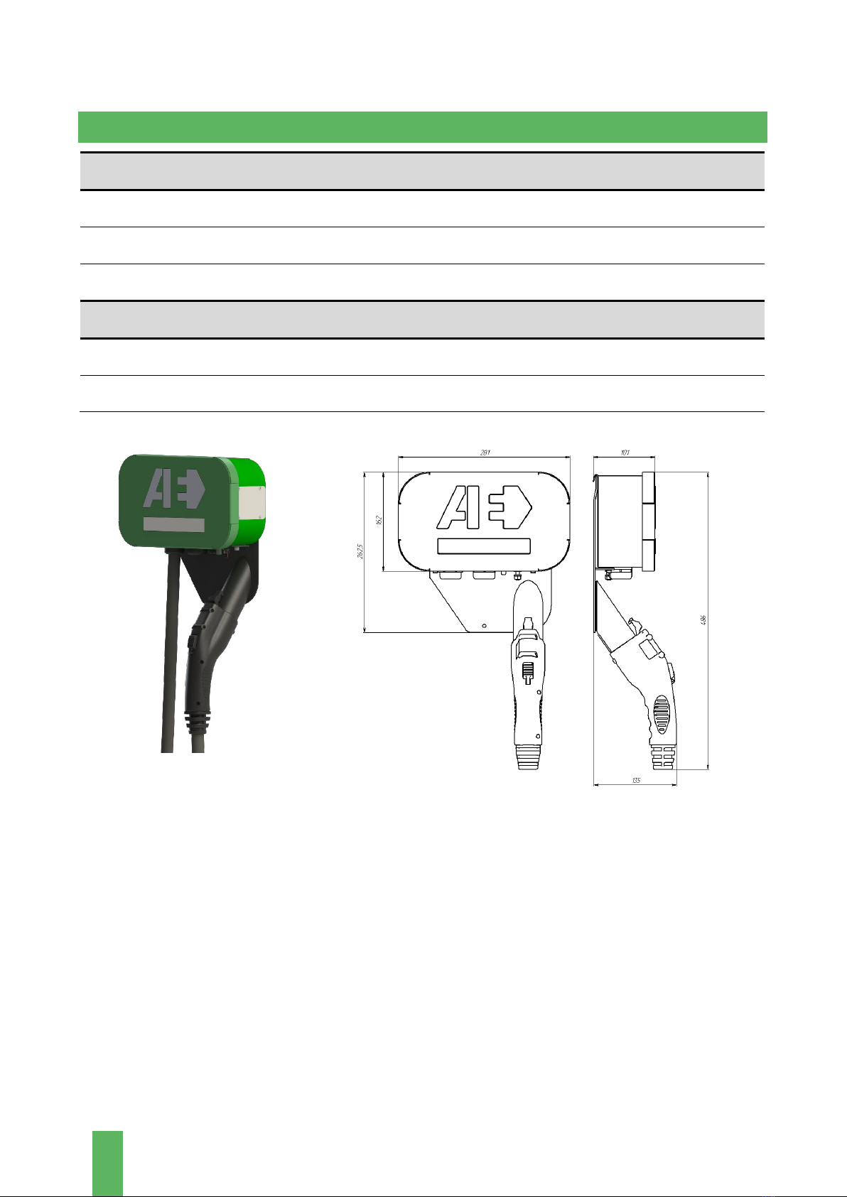
Overall dimensions (H×W×D), mm
365×555×132
Communication (standards and protocols)
2G
GSM GPRS Class 12,
Quad-band: 850 / 900 / 1800 / 1900MHz
3G/4G (LTE)
LTE Cat 1,
LTE-FDD: B1/B3/B7/B8/B20/B28A;
GSM: B3/B8
RFID
ISO 14443 (A) (Mifare)
Ethernet
IEEE 802.3
Wi-Fi
802.11 a/b/g/n
OCPP
OCPP 1.6
SINGLE OPERATING MANUAL
8
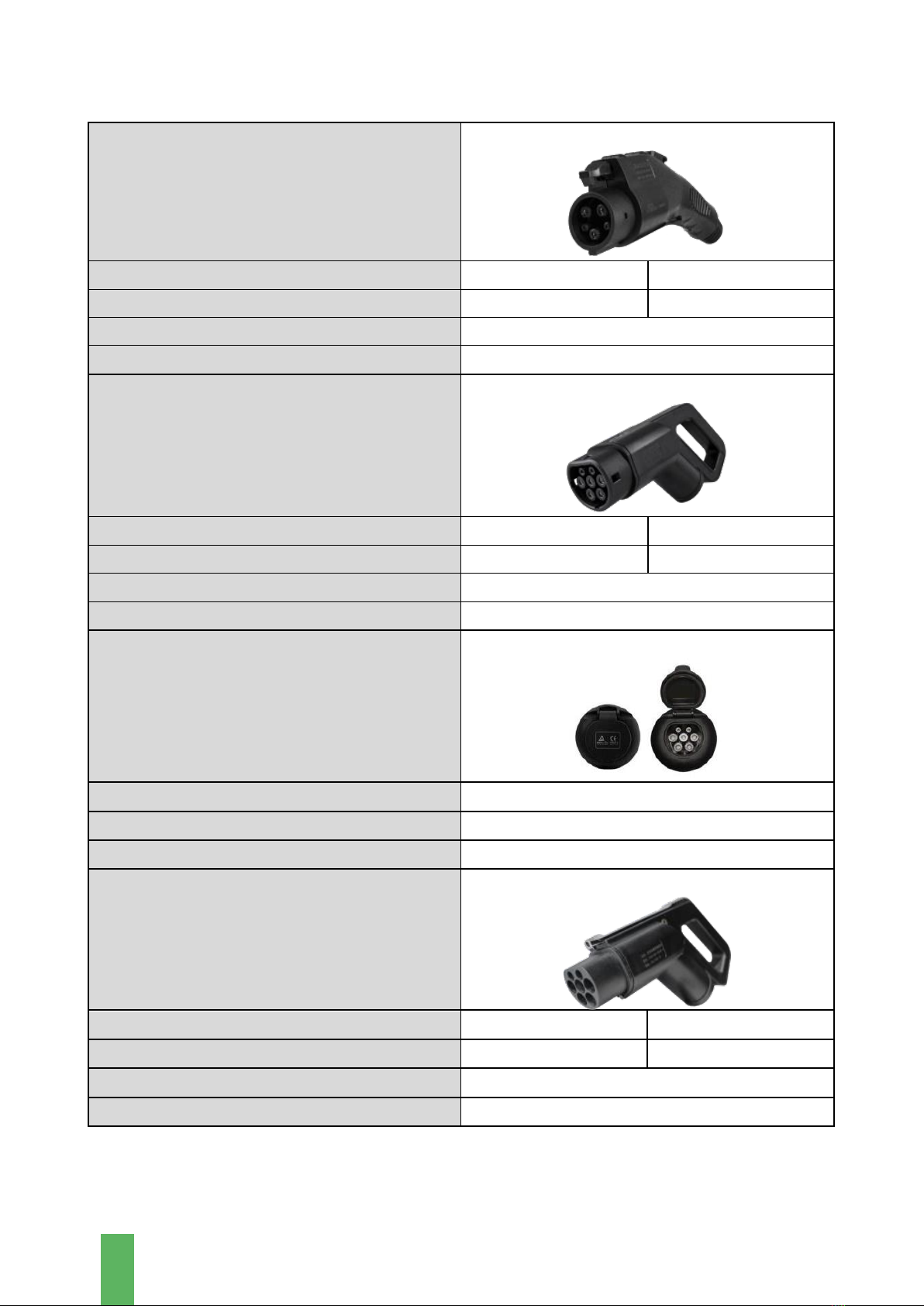
1.4 CHARACTERISTICS OF THE STATION CONNECTORS
Charging station port
Type 1 (SAE-J1772)
Maximum output power
9.2kW
18.4kW
Maximum charge current
40A
80A
Maximum charge voltage
230V
Cable length
6.5m
Charging station port
Type 2 (Mennekes)
Maximum output power
22kW
43kW
Maximum charge current
3×32A
3×63A
Maximum charge voltage
400V
Cable length
6.5m
Charging station port
Socket Type 2
Maximum output power
22kW
Maximum charge current
3×32A
Maximum charge voltage
400V
Charging station port
GB/T AC
Maximum output power
22kW
43kW
Maximum charge current
3×32A
3×63A
Maximum charge voltage
400V
Cable length
6.5m
SINGLE OPERATING MANUAL
9
1.5 CHARGING STATION MODIFICATIONS
Charging Station modifications can be with any one connector or socket. Moreover, the
Charging Station can be produced for commercial or individual use.
In the case of its commercial use, the Charging Station is equipped with a modem and to use it,
you need to insert a SIM card.
In the case of its individual use, instead of the information display, an indicator panel, which
displays the maximum possible charge current produced by the Station, is used. In order to
change it, it is necessary to rotate the regulator at the ChS bottom.
SINGLE OPERATING MANUAL
10
2 COMPLETE SET
Wall mounting
Single Charging Station
1
Operating Manual
1
Mounting bracket
1
Floor mounting
Single Charging Station with pedestal
1
Operating Manual
1
Figure 1a –Appearance and dimensions of the Station for wall mounting

SINGLE OPERATING MANUAL
11
Figure 1b –Appearance and dimensions of the Station for floor mounting
3 LABELLING AND MARKING
The labeling and marking of the Charging Station is made on the nameplate located on the side
panel of the Station case.

SINGLE OPERATING MANUAL
12
4 SETTING-UP PROCEDURES
4.1 OPERATING RESTRICTIONS
The Charging Station is designed exclusively for charging electric vehicles.
Please charge only compatible e-vehicles.
Failure to comply with the requirements for operation, technical maintenance,
and repair described in this Manual excludes any liability of the Manufacturer in
the case of malfunctions in the Station operation.
According to IEC 60947-1, the installation altitude of the Charging Station above sea level
should not exceed 2,000m.
Please follow the safety instructions to avoid injury and material damage when working with
the Station.
During the installation and operation of the Charging Station, the following should be
observed: the Rules for the Design of Electrical Installations, the Rules for the Technical
Operation of Electrical Installations of Consumers, the Safety Rules for the Operation of
Electrical Installations of Consumers in terms of electrical installations up to 1,000V, according
to GOST 22261.
By the method of protecting a person from electric shock, the Charging Station corresponds to
Class 1, in accordance with GOST 12.2.007.0.
4.2 CHARGING STATION MOUNTING
Please make sure the installation site has adequate GSM or 4G (LTE) cellular coverage. Cellular
repeaters may be required to ensure good signal strength in underground garages or other
enclosed parking lots.
SINGLE OPERATING MANUAL
13
It is recommended to locate the Station
under a canopy to protect it from direct
exposure to precipitation and sunlight.
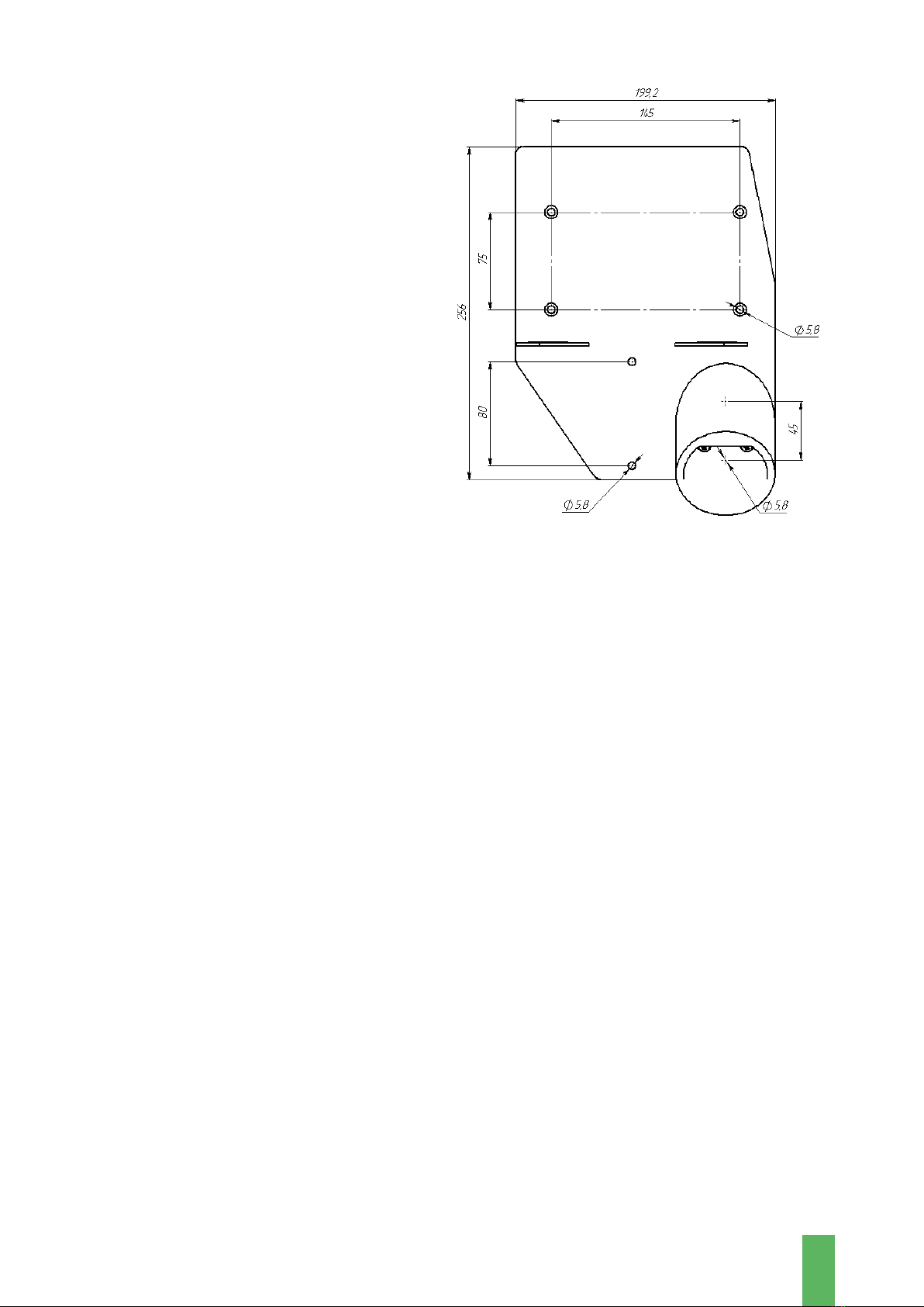
For wall-mounted Charging Stations, a
place should be prepared for attaching the
bracket. When choosing the location of the
Station, please keep in mind that there must
be a distance of at least 0.5 meters to the
left and right of the Station building to any
obstacle. The holes for the anchor screws
should be positioned as shown in Figure 2.
Figure 2 –Mounting plate
For pedestal Charging Stations, the site should be prepared in advance by following the
instructions below.
When choosing a location for the Charging Station, the following conditions should be met:
there must be a distance of at least 1 meter between the case of the Charging Station and a wall
or any obstacle. Adequate space for servicing should be provided in front and behind the ChS.
The Station shall be installed on a foundation (a prepared concrete foundation) measuring
900×900×300mm. Underground utilities should not be laid in the foundation area.
The foundation shall be poured into a well-rammed base with a pre-laid cable duct and a placed
metal insert. For the foundation, it is necessary to use a mixture of crushed stone with cement
at least M400. The surface of the foundation should be carefully leveled to avoid distortion of
the Station during mounting.

SINGLE OPERATING MANUAL
14
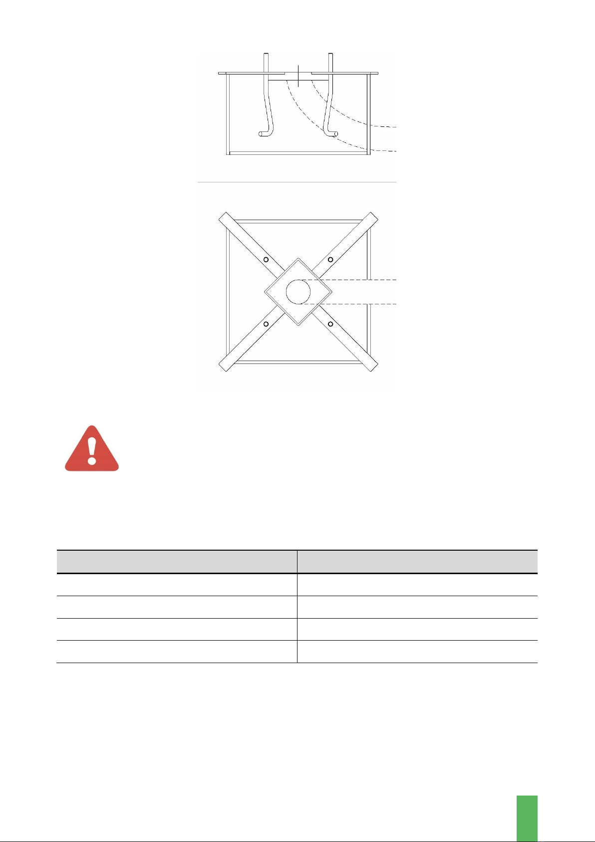
Figure 3 –Appearance and dimensions of the insert
The dimensions of the pedestal
foundation of the Charging Station are
shown in Figure 4, the thickness of the
plate is 5mm.
Along with the preparation of the
foundation, it is necessary to ensure
the laying of the power electrical cable
(not included in the delivery set). The
required cable length above the
foundation is at least 2 meters.
Figure 4 –The pedestal foundation (bottom view)
SINGLE OPERATING MANUAL
15
Figure 5 –The Station foundation
WARNING!
Only qualified personnel should connect the power cable to the AC mains.
It is recommended to select the cross-section of the power cable based on the ChS power
(copper stranded conductor with a cross-section of 5×16mm2to 5×25mm2).
Table. Recommended cross-section of power cable
Charging Station power, kW
Power cable cross-section, mm2
16
5×2.5
32
5×6
40
5×10
80
5×35
When laying the power cable, an AC circuit breaker should be installed between the Station
and the mains. Depending on the Charging Station power and the number of connected phases,
it is recommended to use a 2-pole (for single-phase connection), 4-pole (for three-phase
connection) circuit breaker in the range from 16A to 80A.

SINGLE OPERATING MANUAL
16
4.3 CONNECTING THE CHARGING STATION
After the Station has been transported, before installing it, please make sure that all internal
elements are properly fixed and there is no mechanical damage.
The Charging Station does not require any special settings and adjustments before being put
into operation.
Before connecting the Charging Station, please make sure that:
•The mains supply cable is de-energized by external disconnecting devices.
•The mains power input has a connection diagram: 3 phases with separate neutral (N) and
ground (PE) conductors.
•When connecting with a 4-wire cable, please carry out the protective grounding with a
separate wire.
Depending on the configuration of the Charging Station, the connection to the external power
supply network can be carried out in several ways:
•To an F-type socket (when using J1772 connector with 16A current limitation);
•To socket CEE type 32A 400V;
•To the terminal block as shown in Figure 6 (for the case using a 3-phase
connection or only L1 for a single-phase connection).
Figure 6
ATTENTION!
THE FIRST CONNECTION THAT SHOULD BE PERFORMED IS THE
GROUND WIRE TO THE GROUND BUS LABELED “PE”
IT IS FORBIDDEN TO TURN ON THE CHARGING STATION WITHOUT A
CONNECTED GROUNDING!

SINGLE OPERATING MANUAL
17
Failure to comply with this requirement may lead to voltage supply to the Charging Station
case, electric shock to service personnel and consumers, as well as to the Charging Station
failure.
ATTENTION!
When connecting the Charging Station to the mains, it is necessary to use a separate circuit
breaker, the power and number of phases of which is calculated depending on the
configuration of the Charging Station.
For the Charging Station with a J1772 connector and a capacity of 9.2kW, it is recommended to
use a single-phase circuit breaker with a breaking current of 50A.
For the Charging Station with a Type 2 connector (Menekes) with a capacity of 22kW, it is
recommended to use a three-phase circuit breaker with a breaking current of 40A.
Further, with the external switching devices, it is necessary to connect the power cable to the
AC network and then to turn the three-pole circuit breakers into the operating position.
In order to turn on the Charging Station, it is necessary to:
•Install the SIM card (if a modem is installed in the Charging Station)) of the mobile network
operator (if an external SIM card is used). To do this, please follow these steps:
-remove the ChS cover by unscrewing two screws on the back of the Station;
-remove the modem cover;
-install a SIM card;
-close the modem cover;
-put on the ChS cover by screwing in two screws on the back of the Station;
•Move the circuit breaker on the switchboard to the operating position (up).
5 INTENDED USE
5.1 OPERATING MODES AND ELECTRIC VEHICLE CHARGING
Information about the ChS operating modes (the state of the connectors and the charging
parameters) is shown on the display. The display also shows data on software versions, a modem
number, the Station number in Autoenterprise billing, a mobile network status, etc.
The information shown on the display depends on the software version and may differ from
version to version.
After the supply voltage is applied, the Station display
shows information about the software version and the
modem serial number.
In the event of a malfunction of the Charging Station, you
should inform the serial number of the modem to the
service center for diagnostics and restoration of its work.

SINGLE OPERATING MANUAL
18
In standby mode, the display shows information about the
status of the connectors.
In the e-vehicle charging mode, the LCD displays
information about charging time, voltage level, and current
value.
5.2 CONNECTING THE VEHICLE
5.3 INDICATION OF SAFETY MEASURES
The Charging Station operating system is powered from the mains through an additional circuit
breaker.
The output cable is connected via grommets/cable glands.

SINGLE OPERATING MANUAL
19
6 CHARGING STATION MAINTENANCE
ATTENTION!
All maintenance work should be carried out by the Manufacturer's
representative or a qualified technician. Do not attempt to carry out
maintenance work yourself, as this may result in electric shock and/or loss of
functionality of the Charging Station.
Improper maintenance can result in a serious injury or an equipment damage. For
this reason, this work can only be performed by authorized, trained personnel
who are familiar with the principles of the Station operation and strictly adhere
to all safety instructions.
The use of explosive or flammable cleaning agents creates a fire or explosion
hazard.
Do not store flammable or explosive liquids near the Charging Station.
ATTENTION!
Please ensure that the Charging Station is de-energized before carrying out any
maintenance work.
During operation, the following routine maintenance shall be performed:
•Visual inspection for the equipment overheating; check, tightening of connections;
•Identification of defective parts, assemblies, their repair and replacement.
Before starting any maintenance or cleaning work on the Charging Station or working on any
circuits connected to the Charging Station, the authorized service personnel should disconnect
all AC sources from the Charging Station to reduce the risk of electric shock.
It is strictly forbidden to modify or alter the design of the Charging Station in any way without
the written consent of the Manufacturer!
All signs, labels, and pictograms placed on the Charging Station must be visible and readable.
Signs, labels, or pictograms that have been damaged or illegible must be replaced immediately.
Please contact the Manufacturer to agree on such issues.

SINGLE OPERATING MANUAL
20
7 TROUBLESHOOTING
Malfunction,
external
manifestations, and
additional signs
Possible reason
Troubleshooting method
Loss of connection
with the server
Modem failure / SIM card
inoperative
Replacing the GSM modem or
checking the status of the SIM
card
Poor signal strength of the
mobile network / The antenna
of the GSM modem failed / The
Station location outside the
coverage area of the mobile
network
Replacing the antenna with a more
powerful one
Damage to the
charging cable or
connector
Physical deterioration, careless
handling of equipment
De-energize the device. Contact
technical support for cable
replacement
The Charging
Station display
does not work
(there is no
information on the
Station display)
No input voltage
Find out the reason for the lack of
input voltage and restore the
power supply
Circuit breakers tripped
Bring the circuit breakers to the
operating position
Display is defective
Contact the Technical Support
Service
Other malfunctions
Malfunctions caused by
external and internal factors
Contact the Technical Support
Service
TECHNICAL SUPPORT
You can contact the Technical Support Service in any way convenient for you indicated on the
website.
Other manuals for Single
1
Table of contents
Other Autoenterprise Batteries Charger manuals

Autoenterprise
Autoenterprise I-STATION User manual

Autoenterprise
Autoenterprise WALL COMPLEX User manual

Autoenterprise
Autoenterprise Travel Charger User manual

Autoenterprise
Autoenterprise CHARGE COMPLEX K Series User manual

Autoenterprise
Autoenterprise I-STATION User manual

Autoenterprise
Autoenterprise EDISON User manual


