Forematic AXEL F730 User manual

www.forematic.com
Underground gate opener
AXEL
AXEL
F730 installation

1Manual edition V1.1
AXEL installation
Page Contents
1Descripon & specicaons
2Responsibilies & consideraon
3Gate mounng
4Driveway layout
5Groundwork & cable ducts
6Pier design & ng
7Control panel wiring
7Commissioning
8 User instrucons
9 Safety record & tutorial
11 Warranty
Descripon
AXEL sets are suitable for presge estate gates. The
powerful PWM motors have internal encoders to
monitor gate posion. Stall sensors detect obstacles
and in order to reverse the gate’s direcon. Speed
and pressure are adjusted in compliance with safety
standards. AXEL sets are safe and green. They will
provide long and reliable service if ed and main-
tained according to the instrucons in this manual.
Remotes use a ‘Rolling Code’ format that changes
the code sent every me it is used. It can’t be cop-
ied, keeping your home secure.
A key operated manual release
mechanism allows access in
case of a power outage.
Though this equipment is com-
plex, user programming has
been kept simple. Foresee
have a planned program of
simple hi technology new prod-
uct releases to keep your home
secure and up to date.
Technical Specifications
Supply volt-
age 220-240Vac Motor power 100W @
24Vdc
Supply rating 2.5A @ 50-
60Hz Motor torque 250Nm max
Standby
power <10W Motor insula-
tion IP67
Ambient
temp -20° to +70° Open angle 100 degrees
Remotes 433MHz
50max Opening speed 4.5° /sec
Duty cycle 60% Max leaf size 2.5m wide, 5m²
area
Noise <70 dB Max leaf 500kgm (weight x
width)
Set contents
AK-424 The standard set is for double leaf
boarded gates, and heavy domesc gates. The
set includes two underground openers, control
panel, two remotes and a photo-beam. RIO-X
control panel requires a 230Vac supply.
AK-414 This single leaf version is approved for
gates leaves up to 2.8m when installed with an
electric lock (not included) or pedestrian gates.
AL-424 This is the AXEL low power set. The RIO-
XL control panel is powered by an ELV source
mounted remotely, oen in the house or garage.
RIO-XL includes 1.1Ahr baeries. Ideal for sites
where a long mains cable would be dicult or
expensive to run. The charging cable can also be
used for an intercom or other controls.
All sets include two remotes and a photobeam
set. Mains powered sets can be ed with the
baery backup set for up to 10 hours o grid.
Without baeries, gates will aempt to close
when power is restored.
Set contents are a starng point. Addional
devices may be added. Further safety devices
may be required. Mains isolator is not included

2
AXEL
Safety consideraons
European standards specify safety measures to
be used on applicaons with perceived risk. The
highest rang calls for photobeams and sensive
edges, in addion to control panel PSR.
Rangs for systems in public spaces used by un-
trained are higher than private gates operated
by trained. Autonomous devices such as mers
and vehicle detectors add a level of risk.
The safety tutorial at the end of this manual is
dedicated to dening ‘risk’. The design and
layout of a gate can eliminate many risks,
avoiding the need for more safety devices.
Control panel electronic measures do not make
the system compliant on their own.
Double leaf set
2x motor casings
2x motor gearboxes
Control panel with remote receiver
2x IR safety photo-beams
2x remote controls
Installer responsibility
An automated gate is a machine that must
comply with the EU Machines direcve. There
are many aspects of compliance that ensure the
gate is safe to users and public. ‘Automac gate’
signs are required on both sides of the gate
warning against risk of contact injury.
The installer must prepare a handover pack to
include details of the installaon, a user guide
and a risk statement. Much of that informaon is
included in this manual, along with guides to
indenfy site specic risks and gate aributes.
Good pracce is essenal to safety & reliability.
Note outdoor installaons electrical standards.
Homeowner responsibility
It is the responsibility of the owner to ensure
only trained people operate the gate, and they
are aware of potenal gate hazards. Owners are
responsible for injury resulng from failure to
meet the requirements in this manual.
The person operang the gate must take
responsibility for the safety of any person within
the hazard area. Never let children play near
gates in moon.
Gates must be robust, well maintained, and on
clean level ground. Keep the gate area clear of
objects. Have the gate properly maintained and
repaired by qualied personnel to maintain the
legal safety requirements.
3
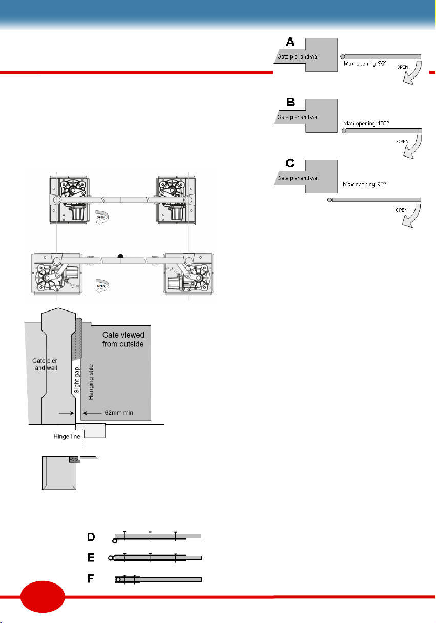
Stepped piers work beer for steel barred gates.
Boarded gates leave an unsightly gap. Filling the
gap is likely to cause a pinch hazard.
Rear hung gates, where the casement is on the
back of the pier (Fig 1c) eliminate the sight gap,
and can hide the necessary safety edge.
However on turning the casement the adjustable
closed stop no longer works. You will need a
centre stop or an alternave casement stop.
The top hinge on a boarded gate is crical to
quality installaon. Top hinges need to be plumb
above the casement pivot. Fig 3 gives some
alternaves.
The most common [D] requires the gate to be
o centre, and therefore will require a safety
edge to protect the pinch hazard.
[E] is on centre, but leaves a sight gap, or you
need to cope with a rear hung gate.
[F] is ideal, but needs a special hinge ng to
the top of the gate.
Be sure to discuss top hinge design with your
gate supplier. The design will aect safety, pier
design, the gate’s dimensions, opening angle and
entrance width.
Fig 1
Fig 3
Gate mounng
[A] is frequently requested, but requires extra safety edges
because of the crush risk between the gate and the pier.
[B] recommended for safety and has a good opening angle.
[C] casement must be turned through 90° and mounted on
the back face of pier. This results in a reduced opening angle.
Fig 4
Fig 2 A & B
C
4
AXEL
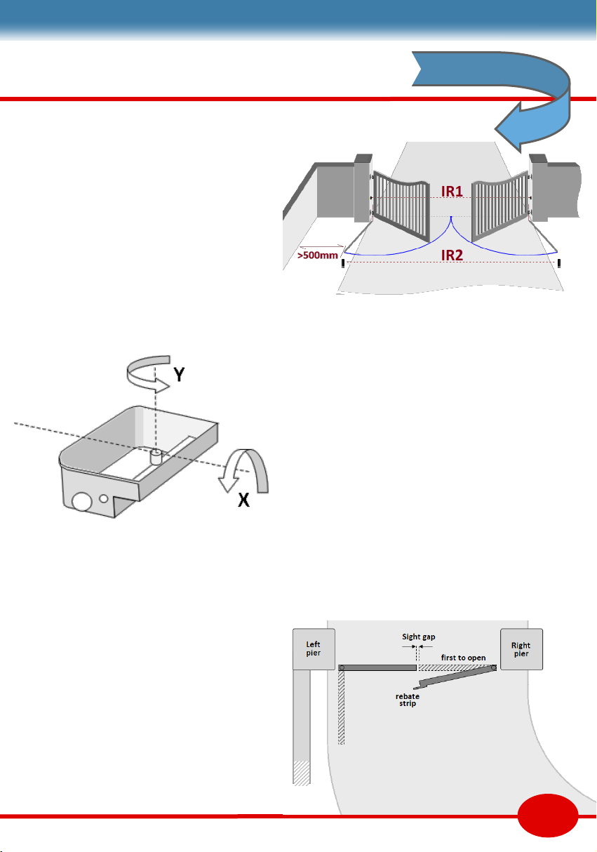
Driveway layout
Layout, like gate mounng, can minimise extra
safety devices without compromising safety.
Sets contain one photobeam, normally wired to
the re-open [F] input. The beam is xed to the
gate pier or post. A second pause photobeam on
[E] input is placed outside the swing of the gate.
The entrance should be on level ground from
pier to pier. The casements need to be at
nished ground level. It is possible to have
casements at dierent heights but one leaf will
need to be adjusted to suit.
Casements need funconing drainage. In most
cases, the drive will be higher than the water
table, so a soakaway may be sucient. Steep
private drives may have regular run os towards
the road that will frequently ll the casement,
then ll the soakaway. Consider a surface drain.
Wood swells when it absorbs moisture. A gap
between gate boards and between gate leaves is
essenal. Any sight gap between leaves can be
covered by a rebate on one leaf. This will dictate
the order that the leaves open and close. This
control panel funcon is also used for drives that
curve inside the property.
On a few occasions, the driveway may be so
steep that it is necessary for gates to open
outwards. This is to be discouraged as it puts the
public at more risk.
Similarly, the casement should be level on both
axes, pitch & roll. However, to adjust roll angle X
can compensate for a steep drive. This needs
careful calculaon that can be viewed on our
webpages.
The return wall on the le, or any other xed
solid feature, should be over 0.5m the area
swept by the gate. Any closer, and a protecon
device may be required.
Fig 6
Fig 5
Fig 7

5
Foundaon depth depends on the ground and
pier weight. Gate width is crical, so it is safer to
lay the rst brick course before ordering the gate
to ensure it ts.
The casements can now be laid on a thin bed of
concrete over the concrete base. Fig7 shows an
alternave method where the casements are
suspended from a level bar resng on the rst
few brick courses. This ensures the casements
are level and packed underneath.
Push t ducts and drains in the casement.
Protect any exposed screw threads and tape up
any holes to prevent concrete ingress. Then
build concrete around the casement to at least
75mm, including under the pivot shelf.
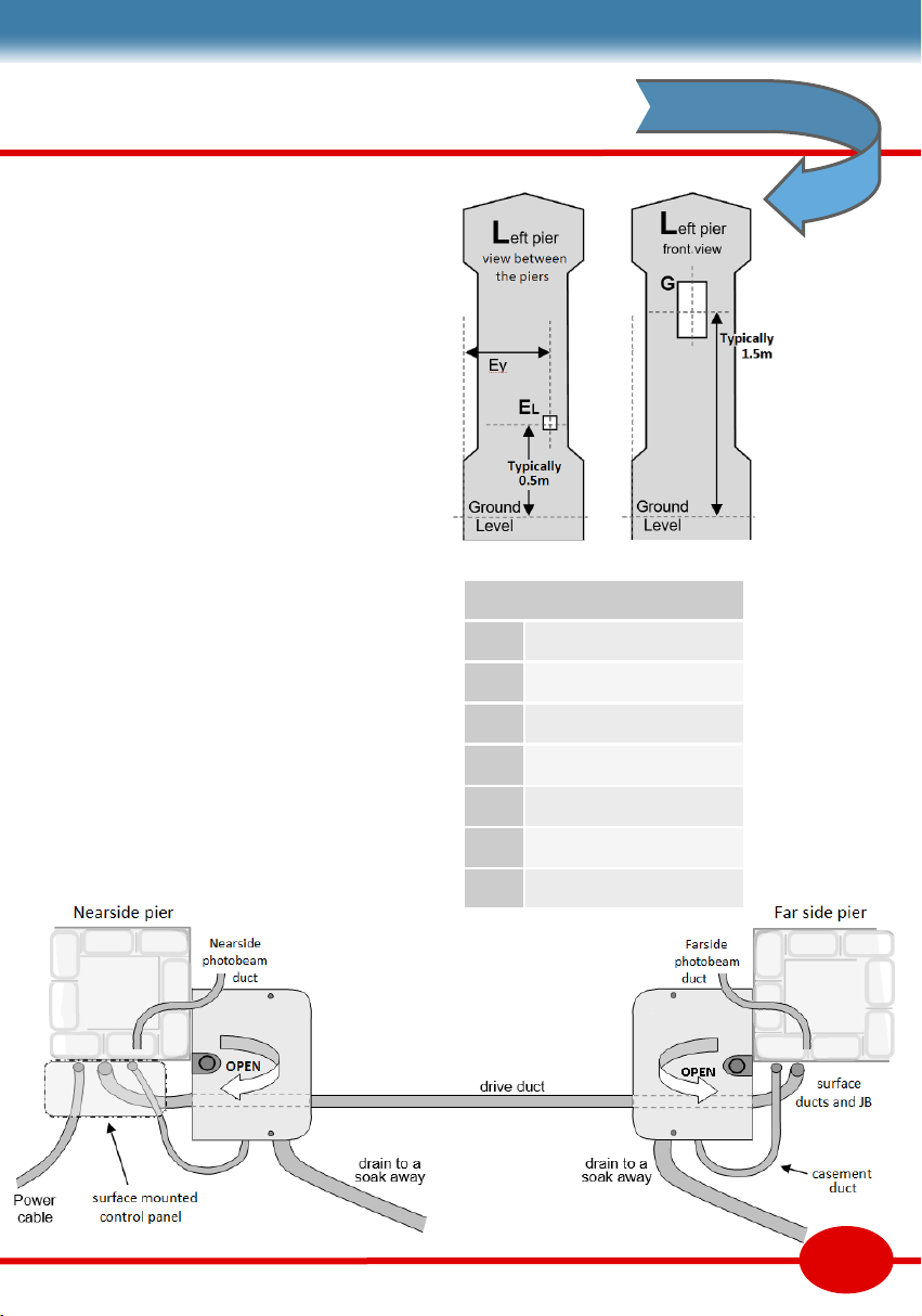
Groundwork & cable ducts
Piers can be constructed hollow, inlled, or with
steel post reinforcement. That is a decision
beyond the scope of this manual.
Two concrete bases are required for the piers,
set at precisely the same level. Level o 170mm
below road level to give casements a solid base,
and space for ducts and drainage to be buried.
More ducts can be laid when the piers are half
height. We recommend 40mm ribbed duct for
cables and 50mm ribbed for drainage. Ducts in
the drawing below are shown terminated at the
base of the pier.
If the pier is to remain hollow, it is dier to run
cable ducts in the pier. If solid, run the ducts up
the side of the pier (Fig 9). It is a sensible prec-
auon to run a pull cord down any long ducts. If
you have the cable, run the cable as well.
Photobeams are set 500mm
above road level. Add a 20mm
duct in each pier run to an
access hole at on the back face.
The far pier has a JB. The near
pier will have the control panel.
Fig 8
Fig 9a Fig 9b
AXEL
Pier design
This is a good point to consider any other ducts
or cables that may be needed. See the accessory
page for more opons, such as an intercom, a
keypad, or a vehicle sensor.
The nearside pier normally has a power supply
cable and the control panel. In these examples it
is shown on the le, but could equally be on the
right. The farside pier has a juncon box (JB) to
make connecons to the motor and photobeam.
If there is an intercom or other access control, it
is normally ed to the le pier, because that is
the side visitors get out of their vehicles. Height
is typically 1.5m. Leave a suitable duct access
hole. Ducts will run either to the control panel,
or to an electrical juncon box on the rear.
Nearside piers are oen the closest to a garage
or the house, where there is a fuse box or
consumer unit. A garage makes a more secure,
safer, and less hosle control panel posion. It
must be within 10m of the gate and will require
more cabling.
Fig 11
6
Fig 10
Duct termination
A Far side JB
B Control panel
C Pier base nearside
D Pier base farside
E Nearside photobeam
F Farside photobeam
G Intercom
7
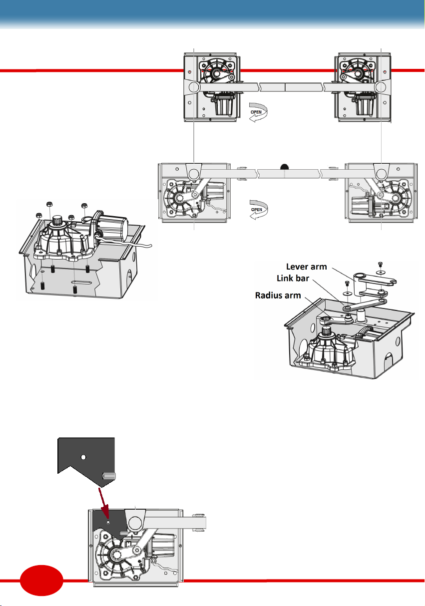
Fing the motors
The 2 casement orientaons are
shown in Fig.12 with the motor
posions. Place the motors over
the casement studs, then bolt
them down.
Gate xing levers will not be
ed unl later, though they are
shown on the diagram.
Stop plates
The stop plate has two limits. The close posion
is adjustable. The open posion is xed to the
limit of the casement. If you need the gate to
open less you can t an addion ground stop.
Fit the stub axle plate and stop plate over the
exposed studs in the upper shelf, then x with
the locking nuts.
Fig 12b
Motor arms
Motor arms can now be assembled on the stub
axle. Grease the motor splines. Place the radius
arm as Fig 14, then tap the arm on with using a
so mallet. Grease the stub axle well then add
the lever arm. Fit the link bar (thick end towards
the motor) and x with two screws..
It will not be possible to set the closed stop unl
the motors are under power.
Fig 13
Fig 14
Fig 15
Fig 12a

Running cables
We recommend star wiring. A ve core 0,6mm
cable (DC519) is run from the control panel to
most devices. Excepons are the motor cables
which are 3 core 1mm, and AK sets mains supply
cable (3 core 5A). Lock and lamp cables may also
dier, so check their cable specicaons.
Cables should enter the panel through glands.
Running the cables behind the PCB keeps the
limited space dy. It is beer to hide cables than
cut them too short. Mark all cables.
The wiring plan below shows individual cables
grouped in appropriate ducts. Only one juncon
box is shown. Others are likely to be required.
Capital leers refer to the terminal they service.
An intercom has been included as an example of
access control. Devices on terminals L, K, G, E
and D are oponal and not included in AXEL sets.
8
Fig 16
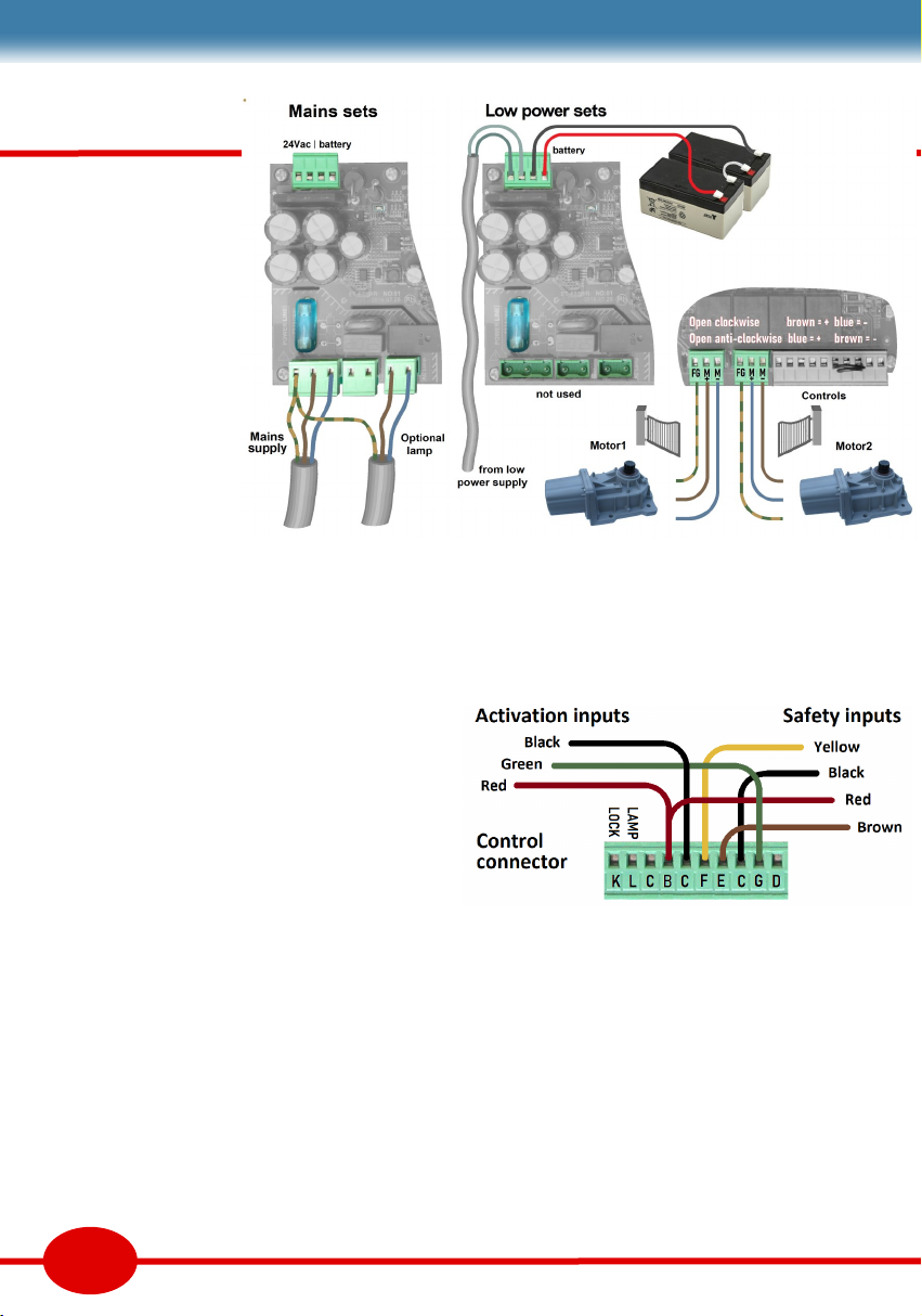
RIO-X panel
RIO-X is the mains
panel with a 24Vac
transformer. The only
other main wiring is
the warning lamp.
RIO-XL is a low power
version with baeries
charged is remotely.
Baeries a can also
be ed to RIO-X
giving about 10hrs o
grid service.
CONTROL WIRING
The 10 way control connector is for ‘acvaon’
and ‘safety’ devices. A standard colour scheme
simplies diagrams. Black [C] is common to all
devices. Use only compable devices.
WARNING LAMP [L & C] output gives 12Vdc
ON-OFF while the gate is in moon for lamps
without a asher circuit. The power board has
terminals for 230V lamps with internal ashers.
ELECTRIC LOCK [K & C] opon gives a DC pulse
on opening. Use wire over 1.5mm terminals.
ACTIVATION DEVICES [G & C] or [D & C]
Any number of extra acvaon devices can be
wired to [G & C]. Some examples are shown on
the next page. Move the green wire to [D] for
single leaf “door” opening. Remotes can be set
for these two funcons. See user instrucons.
SAFETY DEVICES [F & C] or [E & C]
There two inputs are for safety devices. Input [F]
prevents the gate closing (outside photobeams).
Devices on input [E] pause gate while opening or
closing (eg inside photobeam or safety edge).
See examples on the previous page.
Unlike acvaon devices, safety device contacts
are ’NC’. More than one device contact on the
same input need to be connected in series. If an
input has no device connected, it needs to be
linked to [C] common.
Examples on page 12 show single photobeams
on each input. Below that, there are examples of
a photobeams with one and two safety edges.
Safety device power (red) is 24Vdc. It is only
acve while the motor is running.
We recommend safety edges with an NC contact
for easy wiring. Not all edges need the power
supply. Resisve edges may need a processor.
Safety is a synergy of all measures and devices.
Refer to the safety tutorial for risks & soluons.
9
Fig 17
Fig 18

Control terminal functions
Lock output, 24Vdc K
Lamp output , 24Vdc L
Black Lamp & lock common C
Red Accessory power A
Black Common C
Yellow Safety, re-open F
Orange Pause either direction E
Black Common C
Green Full opening input G
Pedestrian opening D
Accessories below have NO contacts. FORESEE’s wireless buon
& keypad work on the remote channel so require no wiring.
Exit buon is normally in the property. A keyswitch can
on either side, or for use by authorised persons only (eg teachers)
Vehicle sensors are normally used for leaving the property,
oen described as ‘free exit’ sensor. A single point vehicle sensor
is placed in the driveway. Adding a me clock to work during the
day could be viable ‘free entry’ device for a commercial property.
Keypads are useful for friends, family or trusted delivery
drivers. This keypad can accept many codes, and some for single
use (less trusted delivery drivers).
Intercoms normally require a cable to the house. These two
types need only 2 wires (not shown here), which can be included
in a ’Low Power’ RIO-XL ’s power supply cable. Intercoms and
keypads are normally on the le pier to suit visitors by car.
Smartphone control oers a modern control method with
a device we all carry. A data cable to the house is not necessary
for simple control, but adds features if it is included at this early
stage. They can replace the intercom and addional remotes.
Acvaon device wiring
10
VY805
buon
FA61
Keyswitch
K15
Keypad
202
Audio intercom
502
Video intercom
VD909
vehicle
Sensor
Fig 19a-d
11
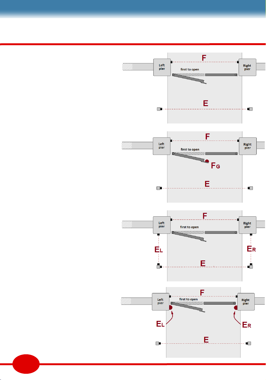
Further wiring plans
There are 2 safety inputs. [F] stops the gate
closing (Fig24). [E] pauses the gate in either
direcon (Fig25). More safety devices may
be added as required. Refer to the safety
page for guidance on the risks.
Mulple safety contacts must be wired in a
chain (series) on the same input. Photo-
beams have a receiver [Rx] and transmier
[Tx]. It helps if the beam direcon on [F] is
the reverse of the beam direcon on [E].
Fig20 The primary beam is [F]. An inside
beam [E] is recommended, ed to posts
or a wall. Note the hinge posion is on the
pier corner, so nger traps are less likely.
Fig21 An safety edge has been added to
the gate leaf that closes last. There are now
two devices on [F] wired as Fig26 or Fig27.
Fig22 This ring of photo-beams stops gate
movement if there is any incursion into the
area enclosed. There are 2 repeater posts
that need only power (Fig29). Fig25 Tx is
the start, and Fig25 Rx is the end of chain.
Fig23 The gate hinges have been moved
making a nger trap risk. Safety input [E]
needs 2 safety edges and a photo-beam.
Wire to Fig26 (le) and Fig27 (right).
SAFETY EDGES
DRI safety edges have a 4 core cable (Blue-
yellow-black-red) that needs power. Fig30
shows the alternave DCY or DTE edges.
Fig 20
Fig 21
Fig 22
Fig 23

12
AXEL
Optional
FA31 on
input E
standard
FA31 on
input F
Photobeam wiring
The first photobeam on F (yellow) is
compulsory. The E input (brown) is
optional. Inputs can take multiple
safety devices when
their volt free contacts
are wired in series.
Note jumper position !
Beam Fig 26
DRI edge
on the end
of the gate
E or F
power
Beam Fig 27
One DRI
edge on
on a pier
power
Beam Fig 28
Wiring 2 DRI’s
Yellow NC
Blue Com
Black Gnd
Red Supply
power
Open Timer
A wired switch or mer can hold a gate
open. The N/O contact opens the gate
[G]. The N/C contact stops it closing [F].
This circuit comes between RIO-X and
safety circuits on this page.
Fig 31
Fig 24 Fig 25
Beam Fig 30
DCY
or DTE
edges
power
Beam Fig 29
Power
Repeater circuit for ring of
beams. Each Rx enables the
next Tx. Only requires power.

13
Stac sengs
Open & close delays - DIP1 to 4
The rst leaf needs to start to open a few secs
before the second leaf. There is a similar delay
for closing. If your drive is straight the delays can
be set to minimum, so set all 4 DIPs o.
DIP5 OFF for double leaf gates. Set ON for
single leaf gates, connected to ‘Motor1’ output.
Auto-close delay - DIP11 to 13
Delays start when both gates are open. Delay is
set on DIPs 11-13. All DIPs o disables the auto-
close funcon. The table below gives delays.
Electric Lock
Can be set as an electro-lock or locking magnet.
The electro-lock can be set to 24Vdc or 12Vdc.
Maglock is 24V except while the gate is opening.
DIP15 OFF = electro lock ON = Maglock
DIP7 OFF = 24V lock ON = 12V lock
Opening order - DIP14
Sets which gate opens rst (and pedestrian gate)
DIP14 OFF; motor1 leaf opens rst, closes last.
DIP14 ON; motor2 leaf opens rst, closes last.
Motor1 is normally on the le pier. See page 13.
DIP11,12,13 Auto-close delay
100 010 110 001 101 011 111
5s 15s 20s 60s 65s 75s 80s
Delay 2s 3s 4s 5s
DIP 1&2 - opening 00 10 01 11
DIP 3&4 - closing 00 10 01 11
PCB buons
There are two buons on the PCB. The CODE
buon is used to set remotes. STEP is the same
as receiving an input on the [G] terminal.
Seng remotes
You can save up to 50 remotes. There are two
remote channels. Pedestrian channel opens one
gate only. Main opens both leaves.
Press and hold the ‘code’ buon for 2 secs.
LED1 will light. Press any buon on the remote
twice. LED1 now goes out.
Pedestrian opening - Press the ‘code’ buon
for 1 secs. LED1 will light. Press the ‘code’
buon again for 1 secs. Press the boom
remote buon twice. LED1 now goes out.
Remote funcon
In both states, assuming an auto-close delay is
set, a single remote buon press will open the
gate, pause for auto-close delay, then re-close.
4step auto sequence is ;
OPEN—STOP—CLOSE—STOP
Gate moon can be stopped at any point by
pressing remote buon. The next press
reverses direcon. If you want to hold the gate
open, wait unl the gates are almost open, or
just beginning to close, then press the remote
again to pause. Release with another press.
Remote funcon - DIP6
In both states, assuming an auto-close delay is
set, a single remote buon press will open the
gate, pause for auto-close delay, then re-close.
4step auto is default (DIP6 OFF) sequence is ;
OPEN—STOP—CLOSE—STOP
Gate moon can be stopped at any point in this
sequence by pressing remote. The next press
reverses direcon. If you want to hold the gate
open, wait unl the gates are almost open, then
press the remote again to freezes the gate.
Release with another press.
2 step auto (DIP6 ON) is OPEN - CLOSE only. If
the remote is pressed while the gate is opening,
it stops and re-closes (or vica versa). No pausing
the sequence; no gate hold open funcon.
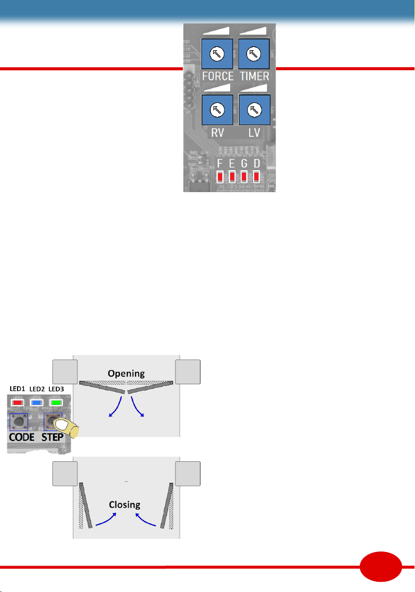
LED3 ashes while opening
LED3 stays on when open
LED2 ashes while closing
LED2 stays on when closed
Fine adjustment
Fine adjustments set the safe
running of the gate. Follow the
order below. Extra acvaon and
safety devices can be wired in
aer these adjustments without
the need to re-adjust.
RV. Mid travel speed. The gate should only run
fast when it is at least 500mm clear of know
objects. Set heavy gates to run slower.
__________________________________
LV. Speed at slow start & slow stop. Set to close
the gate rmly against the post. LV is a preset
percentage of the total run me.
__________________________________
Force. Regulates the maximum force applied by the
motor before obstacle detecon kicks in. Set
it high enough to move the gate reliably, yet
sll reverse on an obstacle.
__________________________________
Timer. Sets the default run me (30-63 secs). If the
motor fails to nd a physical stop. It mesout.
Refer to safety tutorial for force test limits. The safe
force limits need to be observed. Adjusng the rst
3 sengs will help comply. The adjustments above
should not aect the limit learning. Small changes in
physical limits may be necessary but big changes
will need the limit learning to be repeated.
Further support
Further wiring applicaons, support and fault
nding can be found on our website on the AXEL
support page.
14
Run me seng
LED1 Programming indicator
LED2 Flashes while closing. On when closed
LED3 Flashes while opening. On when open
LED4 Indicator for input [F]. On when safe.
LED5 Indicator for input [E]. On when safe.
LED6 Indicator for input [G]. On when acve
LED7 Indicator for input [D]. On when acve
Limit learning - DIP8
RIO-X uses encoder feedback from the motors to
monitor movement. On a test run, it can detect
the ends of travel set by physical stops allowing
it to nd its own limits and set slow down points.
The DIPs and remotes should have been set. The
four blue pots should be set to 10 o’clock (as
picture opposite). Pots will be ne set later.
Close the gates (this may need a 12V baery).
Set DIP8 to ON. Press STEP to start learning.
Fig 32

15
Deleng
remotes
You cannot delete remotes one at a
me. Delete all. Re-enter the ones
you want to keep. Press and hold
the ‘code’ buon for 8 secs. Delete
will not work while gate is moving
User Instrucons
Safe operaon
Installers must hand the gate over in a safe state.
Use a ‘competent person’ to keep the gate in
compliance with safety direcves. The home owner is
obliged to maintain the system in a safe state, and
keep maintenance records which will be passed to
new owners of the property.
Don’t let children operate or
play on the gate. Keep remotes
out of reach of children. Check
the safety device’s funcon of
once a month. Do not modify
the gates, as this will require a
new safety audit.
Fault nding
In the event of a failure, homeowners should seek
professional help to maintain safety. Our website
PICO support page has fault nding support.
You can save up to 50 remotes. There are two remote channels.
Pedestrian channel opens one gate only. Main opens both. You
will need to open the control panel to nd the ‘CODE’ buon. The
control panel will not accept coding while the gate is moving.
Add a remote
Press and hold the ‘code’ buon for 2 secs.
LED1 will light. Press
any buon on the
remote twice. LED1
now goes out.
Pedestrian opening - Press the ‘code’ buon
for 1 secs. LED1 will light. Press the ‘code’ buon again for 1 secs.
Press the boom remote buon twice. LED1 now goes out.
Manual release
Each leaf has a key release mechanism for
use in case of power failure. The key hole is
at the boom of the gate behind a round
plasc cover. Turn the key then pull the lever
towards you. When the lever has turned
through 90° the gate is be free to open. Be
sure to keep the keys in a place which is
accessible from both sided of the gate.
Fig 33
Fig 34

LED1 indicates a correct remote is being received,
or that you are in limit or remote learning mode.
LED2 Flashes while closing. On when closed.
LED3 Flashes while opening. On when open
LED4 Indicator for input [F]. On when safe.
LED5 Indicator for input [E]. On when safe.
LED6 Indicator for input [G]. On when acve
LED7 Indicator for input [D]. On when acve
LED8 Indicates the baeries are charging
Motor checks - 3 ohms between blue & brown.
Safety
DIPs
16
1 2 3 4 5 6 7 8 11 12 13 14 15
FORCE % TIMER % LV % RV %
1 User record
2
3
4
5
6
Input Position Device
F FA31
Installation record complete this table as part of your records
Activation
Input Position Device / code
G
Fault nding
There are 8 LED’s on RIO-X that show the states
of inputs and the gate posion.
Gate runs slowly This happens when there
has been a loss of power. The controller needs
to re-nd it’s limits. This is done automacally.
Gate will not close Check LED’s 4&5. They
should be ON unless a safety device is acve.
Randomly triggers There may be a missing
remote, or loose wiring in [G] or [D] .
Gate stops before fully open or closed.
Can be the stall detector has sensed an object.
Check for s or dry hinges. Increase FORCE pot.
LED3 ashes 4 mes - cannot nd the limit.
Gate will not operate - Are there any LED’s
on? Check power in, baery voltage and fuses.
Isolate wiring thus; link [E] to [C]. Link [F] to [C].
Empty terminals [G] and [D]. Does it now work
on remotes?
AXEL
Overview
The gate installer builds a machine on site. The
machine must be declared safe by the builder and
comply with the EU Machinery Direcve. Parts for
the machine must be compliant and used as
directed by the manufacturer. Standards require
good design and good working pracces. Finished
machines must be declared safe. Handover to a
responsible person includes documentaon and
training to maintain the machine’s safety for users
& public. The latest DHF TS011 Code of Pracce
can be found at www.dhfonline.org.uk
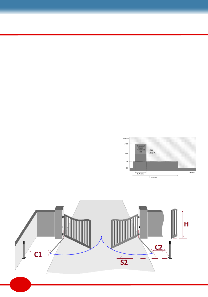
Force tesng
EN12445 explains the method of tesng the
impact forces of a gate. The crux is a graph of
acceptable forces from the point of impact.
Safety device applicaons
Safety devices such as sensive edges and photo
beams are to stop, and if necessary, reverse the
gate movement in the “Risk Zone”. Applicaons
necessary for safety are primary devices. Other
applicaons that contribute to safety, but are
not necessary are supplementary devices. Some
devices are only rated for supplementary safety
use. Primary devices need to be Cat2 or Cat3 as
dened by EN954-1.
17
Gate Safety Code of Practice
Fig 35
Fig 36

Crush hazards marked C1 to C3
Crushing is between a moving part and a staonary
part. It is most signicant below 500mm when it
may be up to 400N for less than 750ms. Moving
part needs to reverse within 5 secs so that pressure
is released to 25N.
Impact zones marked R1 to R3
Impact refers to a moving object striking a person
outside the crush zone. This is 1400N for less than
750ms. There could be a temporary object (a car) in
the R zones, hence the use of photo-beams.
Safety distances marked S1 & S2,
At least one photo-beam 300—700mm high must
supplement force limitaon. Spacing between the
beams and the limit of the moving part must be less
than 200mm. Nominal spacing between vercal
gate bars is 100mm. Safety must be eecve to H,
the maximum height of the moving part, or 2.4m,
whichever is the least.
Edited from DHF TS 011 Code of Pracce
‘Draw in’ or Shear Gaps where a body
part could be drawn in are not allowed. Limbs have
dierent nominal sizes. Finger gaps need to be less
than 8mm (D2), arms less than 100mm etc. A solid
inll sliding gate needs to be less than 8mm from
the post. Vercal bars on sliding gates (D2) present
mulple shear risks against the supporng post.
Entrapment Ez is an area where a
person can be entrapped without being in contact
with the gate. Entrapment is not permied unless a
manual release is provided inside the zone.
Finger traps F1 is a nger trap as a result
of poor hinge design. Designs must ensure moving
gaps are under 100mm, and either under 4mm or
over 25mm, and the gap changes by less than 20%.
Motor PSR is not an acceptable nger trap soluon.
Hold to run speed of a closing gap in a crush zone
must be less than 0.5m/s. The gate must stop
within 50mm in the crush zone, or 100mm at mid
travel.
This guide is a helpful reference to idenfy risk.
It is not a direcve. It does not suggest soluons. AXEL
18
Fig 38Fig 37

RETRO
Complete your home security with
a Foresee gate automation set
PICO
sliding gate motors for confined spac-
es, sloping drives, and sharp corners
AVANTI
Warranty
Warranty covers defects to the Foresee product proven
attributable to a material or manufacturing fault during the
warranty period. We will repair, or refund, or replace faulty
product with a similar fault free product at our discretion. We
do not accept costs for dismantling, installation, or for
carriage. Parts replaced under warranty are the property of
the warrantor.
The warranty period for Radio Equipment is 24 months. The
period for replacement parts is 6 months or to the end of the
current warranty period, which ever is longer.
Warranty exceptions
The warranty does not cover damage caused through:
Wear & Tear or Improper Installation or Negligent Care or
lack of Maintenance or Misuse or Water ingress or Abnormal
Environmental Influences or Mechanical damage during
Transport or damage through improper Installation or
PRIMO
Garage door opener
Table of contents
Other Forematic Gate Opener manuals


Popular Gate Opener manuals by other brands


Chamberlain
Chamberlain SCS200 Installations

Chamberlain
Chamberlain LiftMaster LM3800A Additional Instructions for Installation and Operation

BFT
BFT ELI-250 manual

GiBiDi
GiBiDi SL 244 Instructions for installations

Keyautomation
Keyautomation 900FT-30 instruction manual

Entrematic
Entrematic Ditec PWR50H Technical manual


