Shark 500KG Specification sheet

MotorforslidinggatesSHARK500/800
Manual for installation andoperation

2
Contents
1.1 SHARK 500/800 productsand accessories..................................................4
1.2 Dim ension...................................................................................................... 5
1.3 Gate variations...............................................................................................5
2.1 Generalnotes .................................................................................................6
2.2 Checks............................................................................................................6
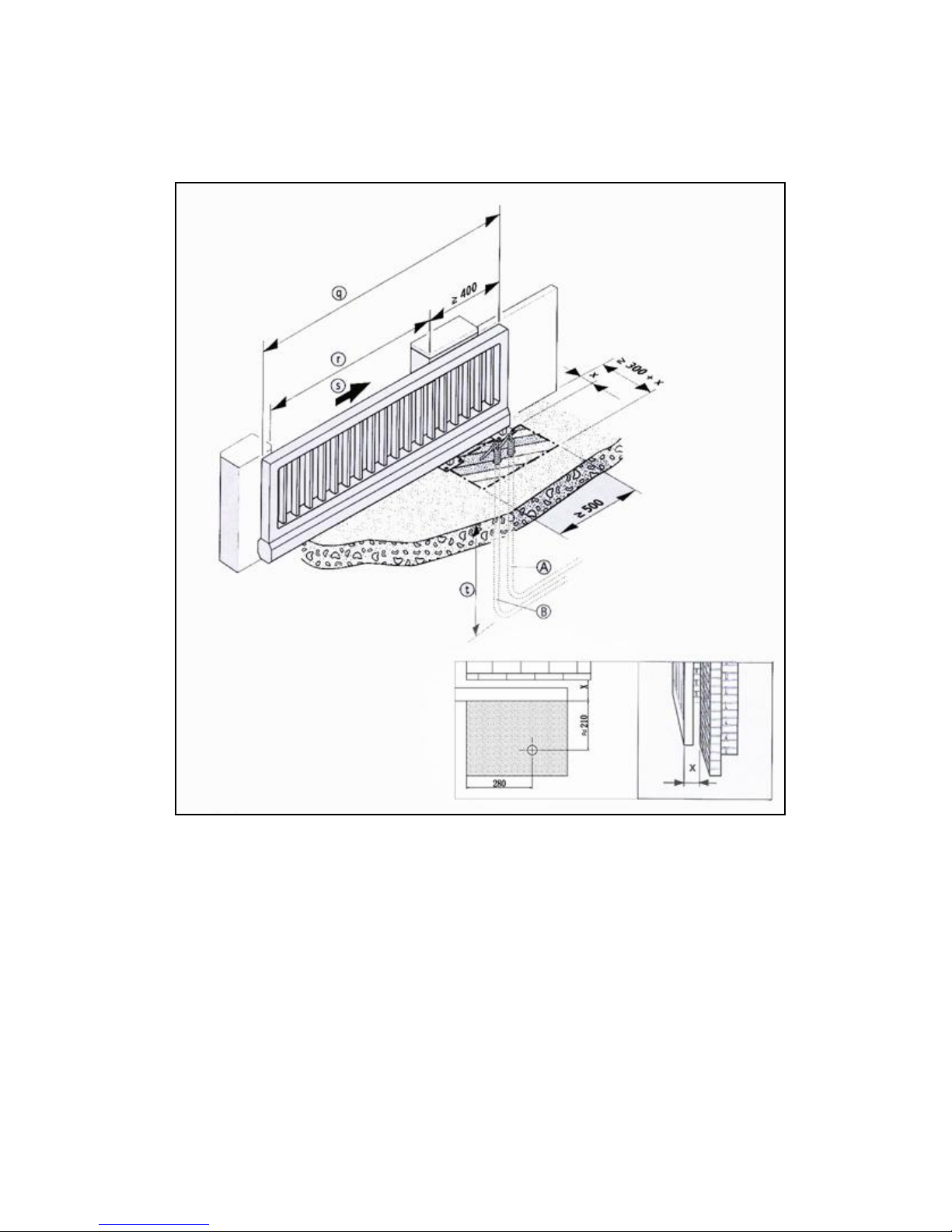
2.3 Gate andfoundation layout............................................................................8
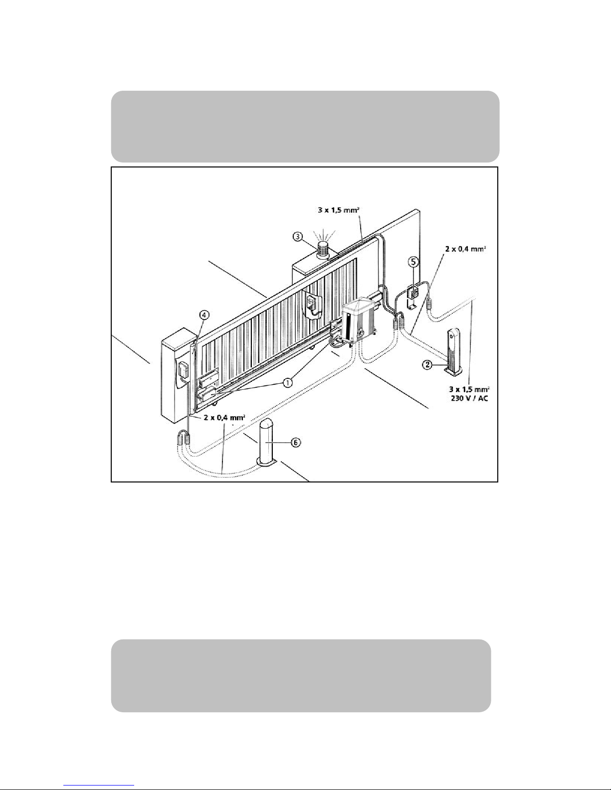
2.4Cabling layout................................................................................................9
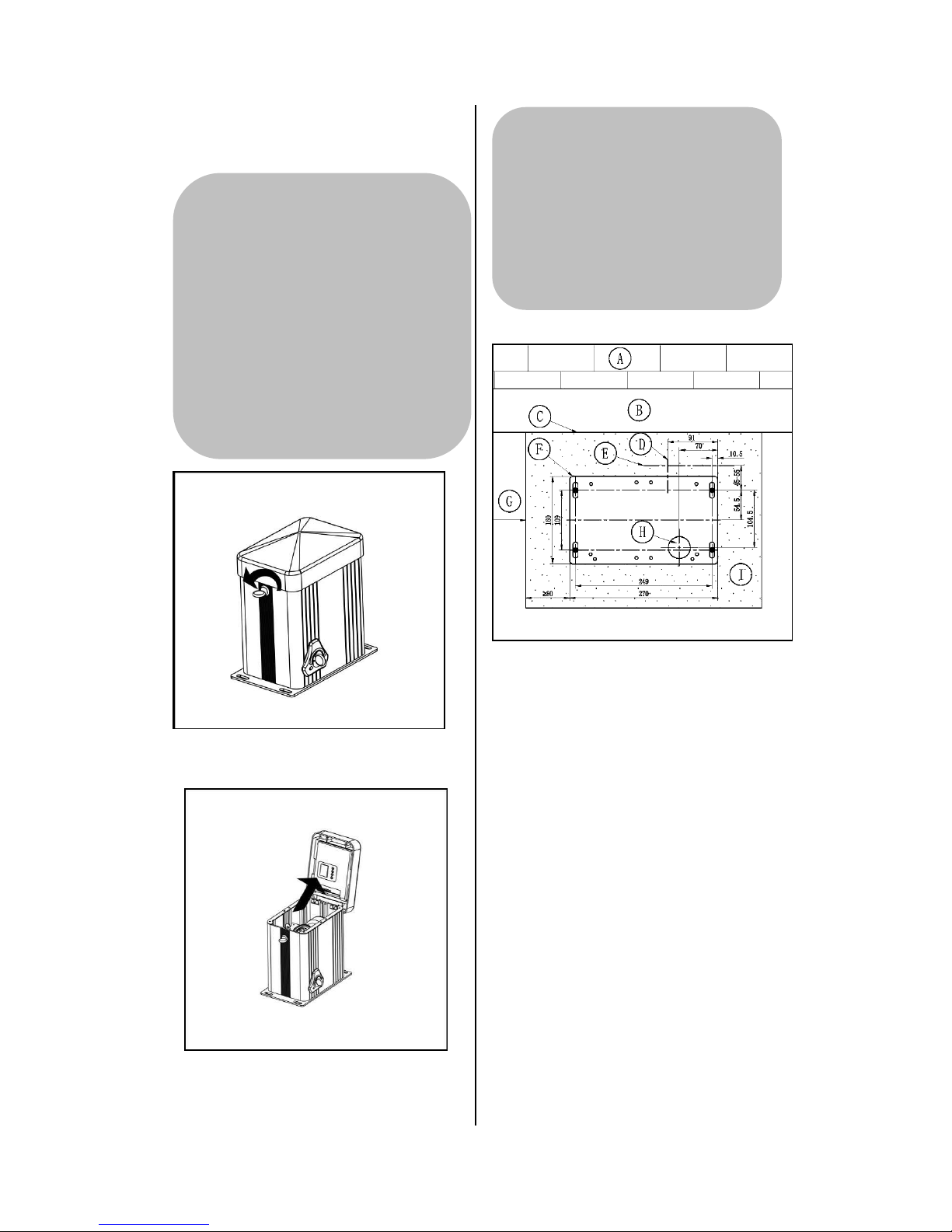
3.1 Installing the m otor unit............................................................................... 10
3.2 Mountingthe toothedrack........................................................................... 12
3.2.1General................................................................................................12
3.2.2Determ iningthe installationheight....................................................12
3.2.3 Determ ining the length and installation position of the toothed rack
...................................................................................................................... 13
3.2.4Adjustthe lengthof the toothedrack...............................................14
3.2.5Mountingthe toothedrack...............................................................15
3.2.6Adjustthe m otor unit.......................................................................16
3.3 Adjusting the heightof the m otor unit......................................................... 17
3.4 Mountingthe reference point m agnet..........................................................17
3.5 Release ......................................................................................................... 19
3.6 Locking .......………… ……… … ………… ……… … ………… ……… ….19
3.7Restore the lim it settingafter power restoration .......................................20

3
4.1 Connection of Mains cable..........................................................................21
4.2 Connection of control elements...................................................................22
4.2.1Wireless closing edge safety device connection..................................22
4.2.2 Infrared beam connection ...................................................................23
4.2.3 Opening edge and closing edge safety device connection .................23
4.2.4 "O/S/C" button connection .................................................................24
4.2.5 Caution light connection.....................................................................24
4.2.6 Battery backup connection .................................................................24
4.2.7 Pedestrian mode..................................................................................24
4.3 Setting the function......................................................................................25
4.4 Hand transmitter coding...............................................................................26
5.1 Technical feature of sliding gate operator....................................................27
6.1 FAQ..............................................................................................................28

4
1.SHARK 500/800
products and accessories
Standard products and accessories
1-1-1
1. SHARK 500/800 motor unit
2. Keys
3. M8 wall plugs
1-1-2
4. Block of magnet housing
5. Reference point magnet
6. Cover of magnet housing
7. Magnet housing
1-1-3
8. Hand transmitter
9. Wall mounting bracket
10. Set screw of bracket
11. Plastic expansion
In addition to the components in the
standard package,the following is
required for the installation:
—Toothed rack
Toothed rack
1-1-4
The toothed rack and accessories
includes:
12.Toothed rack
13.Set screw for toothed rack
14.Washer
15.Fixing nuts for toothed rack
The quantities of the individual
components are dependent on the gate
length.

5
1.2 Dimension
1-2-1
1-2-2
1.3 Gate variations
The standard supply package is suitable
for the following types of gates.
Gate system on rails
1-3-1
Cantilevered gate system
1-3-2

6
2.1 General notes
The picture in these instruction are not
true-to-scale.
All the dimensions are shown in
millimeters(mm)!
The motor can be mounted on the right
or left hand side of the gate depending
on the direction of opening.
These instructions show the motor being
installed on the right hand side.
For correct mounting you will need the
following tools:
2-1-1
* Minimum shaft length is 160mm.
2.2 Checks
Supply contents :
Check the package to ensure that all
the parts are included.
Check that you have all the
additional components that are
necessary for your particular
installation requirements.
Foundations
Check the proposed installation
location for the operator system:
—The motor unit and the toothed
rack must be installed on the
inside of the gate with the gate
closed.
—The motor unit should not be
installed within the clear width!
—For cantilevered gates, the motor
unit must be mounted at the mid
point between the carrier roller
assemblies.
—The foundations must be suitable
for heavy duty wall plugs.
Check whether the existing
foundations are suitable.
Check the supply cable.
Pay particular attention to the cable
exit point where the motor unit is to
be installed.
Attention!
In order to guarantee correct
mounting,carry out the following
checks before installation.
在工作开始前进行以下的检查。
Φ12

7
Gate system
Ensure that your gate system has an
appropriate electricity supply
connection and a facility for
disconnecting the mains. The
minimum cross-sectional area of the
earth cable is 3×1.5mm2
Ensure that all cables are suitable
for outdoor use(cold resistant and
UV resistant).
Check that the gate to be operated
fulfils the following conditions:
—The travel path of the gate must
be horizontal.
—When closed, the gate should
exceed at least 400mm further
than the height on the same
installation side.
—The gate must have a mechanical
gate stop for both direction.
—The closing edges must be fitted
with a flexible gate seal.
—The gate itself must be straight,
so that the distance between
motor unit and the gate never
changes.

8
2.3 Gate and foundation layout
2-3-1
AEmpty conduit for control cable
BEmpty conduit for electricity supply cable
qGate width
rClear width
sOpening direction
tBelow depth of frost penetration
xGate thickness+ distance from structure

9
2.4 Cabling layout
2-4-1
1、Signal transmission system
2、Infrared beam
3、Caution light
4、Closing edge safety device
(SKS)
5、Mains isolater switch(mains
disconnection facility)
Reference:
For the installation and cabling of the gate sensors, control elements and
safety equipment ,the relevant installation instructions must be observed.
Advice:
This is just an example of a cabling layout,the layout can vary according to the
type of gate and the associated equipment.

10
3.1 Installing the motor unit
3-1-1
3-1-2
Open the motor unit cover.
3-1-3
A Wall
B Gate
C Mounting surface for the
toothed rack
D Output shaft of the motor unit
E Front edge of the toothed rack
F Floor console
G Clear width
H Cable entry for power
supply/control cable
IFoundation
Attention!
To install the motor unit correctly,
it must be mounted at the mid
point between the carrier roller
assemblies if the gates are
cantilevered.
Attention!
To install the motor unit
correctly,the following points
must be assured:
—The spur gear must accurately
mesh with the toothed rack.
—The wall plugs for the floor
console must be at least 80mm
from the edge of the foundation.

11
Before installing the motor unit,
check whether the possible height
adjustment of the motor unit is
sufficient for the situation on site,or
if the motor unit needs to be raised
on a backplate.
Align the floor console ,with the
motor unit parallel to the gate.
Drill the holes for the wall plugs as
shown in the drilling diagram.
3-1-4
Push in the wall plugs
Feed the control cable and the
power supply cable through the
floor console.
Adjust the motor unit
Screw the floor console into place
Caution!
Danger of electric shock:
Before commencing cabling
works it is very important to
disconnect the operator system
from the electricity supply.
Ensure that the electricity
supply remains disconnected for
the duration of the cabling works.
Reference:
The height adjustment of the
motor unit is described in section
3.3.
Notes:
When using an existing toothed
rack, the correct dimension is
27mm from the first screw to the
front edge of the toothed rack.
Reference:
When determining the mounting
surface for the toothed rack, the
information given in section 3.2.2
must be observed.

12
3.2 Mounting the toothed
rack
3.2.1 General
Toothed rack are available in several
standard lengths and some fixing rack
accessories.
The toothed rack is made up of several
toothed rack segments.
Minimum length of toothed rack
Minimum length of toothed rack is equal
to the movement stroke of the gate
between the gate OPEN and CLOSED
positions+180mm
Maximum length of toothed rack
Maximum length of toothed rack is
equal to the width of gate.
3.2.2 Determining the
installation height
3-2-1
Determine the installation height of
the toothed rack on the gate
Adjust the height of the spur gear
accordingly.
Notes:
The toothed rack can be adapted to
fit the gate by means of backplate(D).
Reference:
Section 3.3 describes the height
adjustment for the motor unit.
Attention!
To ensure trouble-free movement of the
gate,the following points must be assured:
—The screws(A)should not obstruct the
operation of the gate.(e.g. by extending into
the path of the gate rollers(B).)
—The spur gear(C)should not rest against
the gate.
—The spur gear(C)is should not be too
low to avoid mesh apart with the rack.
(There must be 1-2mm clearance at the
point that meshed)
Reference:
—For gates with an existing
toothed rack,please skip to
Section 3.3.
—Section3.5 describes how to
release the motor unit.
Attention!
To install the rack
correctly,the following
must be ensured:
—The motor unit has been
mounted.
—The motor unit is released.

13
3.2.3 Determining the length
and installation position of
the toothed rack
Maximum length of toothed rack
If a toothed rack is to be installed across
the entire width of the gate ,then the
installation position does not have to be
determined.
The length and installation position of
the toothed rack correspond to the gate
width.
Minimum length of toothed rack
The minimum length of toothed rack
must be determined at the gate.
3-2-2
Move the gate to the CLOSED
position.
Make a mark on the gate:
90mm from the centre of the spur
gear in the direction of opening.
3-2-3
Move the gate to the OPEN
position.
Make a mark on the gate:
90mm from the centre of the spur
gear in the direction of closing.
3-2-4
Attention!
To ensure trouble-free operation,
the toothed rack must at least extend
across the area(E) between the
markings.

14
3.2.4 Adjust the length of
the toothed rack
Measure the required length of the
toothed rack at the gate.
Change the standard length to required
length of the toothed rack:
The toothed rack need not to be
adjusted.
When the standard rack length is
longer than the required length:
3-2-5
When the standard rack length is
shorter than the required length.
3-2-6
Place the required number of the
toothed rack end to end.
Cut off any excess length from the
last toothed rack using a metal
saw.
Cut off the excess length of the toothed
rack using a metal saw.
Attention!
To avoid damaging the
toothed rack segments ,there
should be no toothed rack
segments in the rack housing at
the point where the cut is to be
made.

15
3.2.5 Mounting the toothed
rack
Fixing nuts need to be welded on
different position of the gate before
installing the toothed rack.
3-2-7
3-2-8
Hold the toothed rack in place
according to the fixing rack nuts
welded on the gate on the spur
gear side.
Place the toothed rack onto the
spur gear so that the toothed rack
engages the spur gear.
Adjust the toothed rack
horizontally.
Using a spanner to hold the
toothed rack in position of the
fixing rack nuts.
3-2-9
According to the above-mentioned
process, place other racks with the
bolts to the fixing rack nuts.
Attention!
To ensure correct operation, the
toothed rack must always be pushed
onto the spur gear as the gate is
moved.
Reference:
The reference point magnet
must be installed before the rack is
mounted. Section 3.4 describes
how to install the reference point
magnet.
Attention!
To ensure the gate can move
smoothly, the countersunk screw
must be tightened and adjusted
accordingly.When welding the
fixing rack nuts, make sure to
weld the smaller end to the gate
barrier, and the bigger end face to
the toothed rack. All the surface
of bigger ends must flush with
each other.

16
3-2-10
Push the gate one cycle in the
direction of closing by hand, and
adjust the clearance between the
rack and spur gear.
Tighten all the nuts after adjusting
the height.
3.2.6 Adjust the motor unit
3-2-11
The height of the motor unit must be
re-adjusted now.
Lower the spur gear by 1 to 2mm
Check:
To check that the spur gear
engages the toothed rack along its
entire length,the gate must be
pushed once to the OPEN position
and back to the CLOSED position.
Reference:
Section 3.3 describes how to adjust
the height of the motor unit.
Attention!
To ensure the gate runs smoothly,
it is important that a vertical gap of 1
to 2mm is maintained between the
toothed rack and the spur gear.

17
3.3 Adjusting the height of
the motor unit
3-3-1
3-3-2
According to the Fig.3-1-4,tighten
the bottom screw A after fixing the
wall plug.
Adjust the Nut(B) in the middle of
the wall plug until the motor is in
suitable position.
Tighten screw(C) at the top after
fixing the flat washer and spring
washer.
3.4 Mounting the reference
point magnet
The operator system determines the
gate positions and the extent of travel
electronically. So it requires a
reference point on the gate or on the
toothed rack.
Using a special reference point magnet
as the reference point.
3-4-1
Drive the door to the CLOSED
position
Attention!
To ensure correct operation, any
existing magnets must be
removed.(e.g.in the case of retrofit
measures with an existing toothed
rack).
Caution!
To avoid injury ,the gate must have
a mechanical end stop in both
directions; otherwise it could spring
out of line.

18
Determin the position for the
reference point magnet.
3-4-2
The mounting of the reference point
magnet is dependent on the type of
toothed rack that is used.
3
3-4-4
3-4-5
Mount the reference point magnet
in the magnet housing.
Mount the cover onto the magnet
housing.
Mount the magnet housing at the
previously determined position on
the toothed rack.
Check the position of the reference
point magnet.
Check the distance between the
reference point magnet and the
motor unit.
Check the distance between the
centre of the reference point
magnet and the internal hall height
of the motor unit.
Attention!
To avoid faults occuring, the
following dimensions must be
adhered to without fail:
—The distance between the
reference point magnet(A) and the
motor unit(B) must be 2 to 8mm.
—The distance between the centre of
the magnet(A) and the centre of the
spur gear(C) must be 70mm.

19
3.5 Release
3-5-1
Place the release key into the
keyhole at the bottom of the motor unit.
3-5-2
Hold the triangle plastic part
outside the lock, turn clockwise by
180·until it stops.
Move the door shortly by hand in
the OPEN and CLOSE direction.
The transmission is now mechanically
disengaged from the drive shaft. The
gate can only be moved manually. The
electric circuit in the controls is
interrupted and the controls are out of
operation.
3.6 Locking
3-5-3
Hold the triangle plastic part outside
the lock, turn anti-clockwise by
180·until it stops. Push the door
front and back by hand
to ensure the gear is engaged.
3-5-4
Pull the key out of the keyhole at
the bottom of the motor unit.
The transmission and drive shaft are
now mechanically engaged. The gate
can be driven via the motor. The
electric circuit in the controls are in
operation.

20
3.7 Restore the limit setting after power restoration
When the power restoration, Please use the transmitter or wall switch to open and
close the door for one cycle, then the initial set travel limit will be recovered
automatically. If not, the door opening/closing position will be error.
Attention!
Do not rotate the key !
When re-engage after releasing,
limit movement may happen. Please
use the transmitter or wall switch to
open and close the door for one cycle,
then the initial set travel limit will be
recovered automatically.
This manual suits for next models
3
Table of contents
Popular Gate Opener manuals by other brands

BelFox
BelFox 47-21-i instruction manual

Allmatic
Allmatic KINEO 400 manual

Chamberlain
Chamberlain LiftMaster Professional SW420 owner's manual

CAME
CAME AX3024U installation manual

Nice
Nice ROBUS RB400 Instructions and warnings for installation and use

Tormatic
Tormatic NovoSwing Mounting and operating instructions