Autoglide CABRI-20P User manual

INSTRUCTIONS CABRI-20P
Page 1
SWING GATE OPENER

INSTRUCTIONS CABRI-20P
Page 2
SWING GATE OPENER
INDEX
Warnings 3. Control Box
1. Product Description and Application 4. Settings
1.1 Applications 4.1 Sw1 Dip Switch Setting
1.2 Description of the Automation. 4.1.1 Slowing Down Adjustment
1.3 Description of Devices 4.1.2 Over-Current Adjustment
1.3.1 CABRI-20P Electromechanical
Gear Motors 4.1.3 Gate Auto Close Adjustment
1.3.2 Control Box 4.1.4 Pedestrian Mode Adjustment
1.3.3 Photocells 4.1.5 Flashing Light Adjustment
1.3.4 Radio Transmitter 4.2 Sw2 Dip Switch Setting
1.3.5 Flashing Light 4.2.1 Photocell Adjustment
1.3.6 Electric Latch with Stopper 4.2.2 Close delay of Dual Gate
Operation Adjustment
2. Installation
4.2.3 Electric latch Adjustment
2.1 Notes of Motors in Operation 4.2.4 Deceleration Speed Adjustment
2.1.1 Tools In Installing 4.2.5 Operation Speed Adjustment.
2.1.2 Motors, Components and its
Installation in Illustration 4.2.6 Single and Dual Gate Adjustment.
2.2 Power connection 4.3 LED Indication
2.2.1 Notes for Power Connection 4.4 Transmitter Memorizing Process
2.3 Installation 4.5 System Learning Process.
2.3.1 Preparation for Motor Installation 4.6 Gate Operation.
2.3.2 Installation of the Gear Motors 4.7 Gate Moving Logic.
2.3.3 Flashing Light 4.8 Advanced Operation of the
Transmitter.
2.3.4 Photocells 5. Trouble Shooting.
2.3.5 Electric Latch and Stopper 6. Technical Characteristics.

INSTRUCTIONS CABRI-20P
Page 3
SWING GATE OPENER
Warnings
Please read this instruction manual carefully before the installation of gate-automated
system.
This manual is exclusively for qualified installation personnel.
Autoglide
is not
responsible for improper installation and failure to comply with local electrical and
building regulations.
Keep all the components of CABRI-20P system and this manual for further
consultation
•
Be aware of the hazards that may exist in the procedures of installation and
operation of the gate-automated system. Besides, the installation must be
carried out
in conformity with local standards and regulations
•
If the system is correctly installed and used following all the standards and
regulations, it will ensure a high degree of safety
•
Make sure that the gates works properly before installing the gate-
automated system and confirm the gates are appropriate for the
application.
•Do not let children operate or play with the gate-automated
system.
•Do not cross the path of the gate-automated system when operating.
•Please keep all the control devices and any other pulse generator away from
children to avoid the gate-automated system being activated accidentally.
•Do not make any modifications to any components except that it is
mentioned in this manual.
•Do not try to manually open or close the gates before you release the gear
motor.
•If there is a failure that cannot be solved and is not mentioned in this
manual, please contact qualified installation personnel.
•Do not use the gate-automated system before all the procedures and
instructions have been carried out and thoroughly read.
•
Test the gate-automated system weekly and have qualified installation
personnel to check and maintain the system at least every 6-month.
•
Install warning signs (if necessary) on the both sides of the gate to warn the
people in the area of potential hazards.
INSTRUCTIONS CABRI-20P
Page 4
SWING GATE OPENER
1. Product Description and Applications
1.1 Applications
CABRI-20P is applied for residential automation of single or dual leaf gate. CABRI-
20P has to be operated with electricity and it’s forbidden to be operated by back-up
batteries for normal use. Back-up batteries are only allowed for emergent operation
when there is a power failure, and the gear motors can be released by special keys to
move the gate manually.
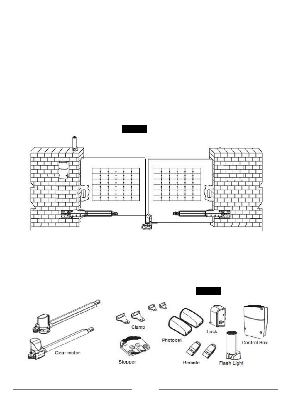
1.2 Description of the Automation
The following diagram of CABRI-20P typical installation describes some
terms and accessories of a gate automation system
Figure 1
1.3 Description of devices
CABRI-20P
includes the accessories shown in figure 2. Please check the accessories
the same as the package provided.
Attn: some accessories not included due to customization
•
2 CABRI-20P electromechanical gear motors with mounting brackets
•
1 pair of photocells.(one TX and one RX)
Figure 2
•
2 Radio transmitters, Flashing Light, Control Box, Electric Latch and Stopper

INSTRUCTIONS CABRI-20P
Page 5
SWING GATE OPENER
1.3.1 CABRI-20P Electromechanical Gear Motors
CABRI-20P
consists of a worm screw reduction gear and a 24V DC motor.
The gear motor could be released manually by special release keys when there is a
power failure.
The gear motor is installed with two post brackets, one rear plate and one front plate
for the installation
. Figure 3
LIST OF SMALL PARTS CABRI-20P
Front Plate 2pcs M8 self-locking nut 4pcs
Rear Plate 2pcs M12*25L hex bolt 2pcs
Post bracket 4pcs M12 self-locking nut 2pcs
M8 *25L hex bolt 4pcs Release key 2pcs
1.3.2 Control Box
Control box consists of one control panel with incorporated receiver and one
transformer. Provides the complete automation of the gear motors and other
accessories of CABRI-20P kit. To connect separate terminals on the control panel
and activate the gear motors and other accessories, the installation manual has to
be carefully read before handling.
Figure 4
LIST OF SMALL PARTS CABRI-20P
5*30 Screw 4pcs
Nylon screw anchor 4pcs
INSTRUCTIONS CABRI-20P
Page 6
SWING GATE OPENER
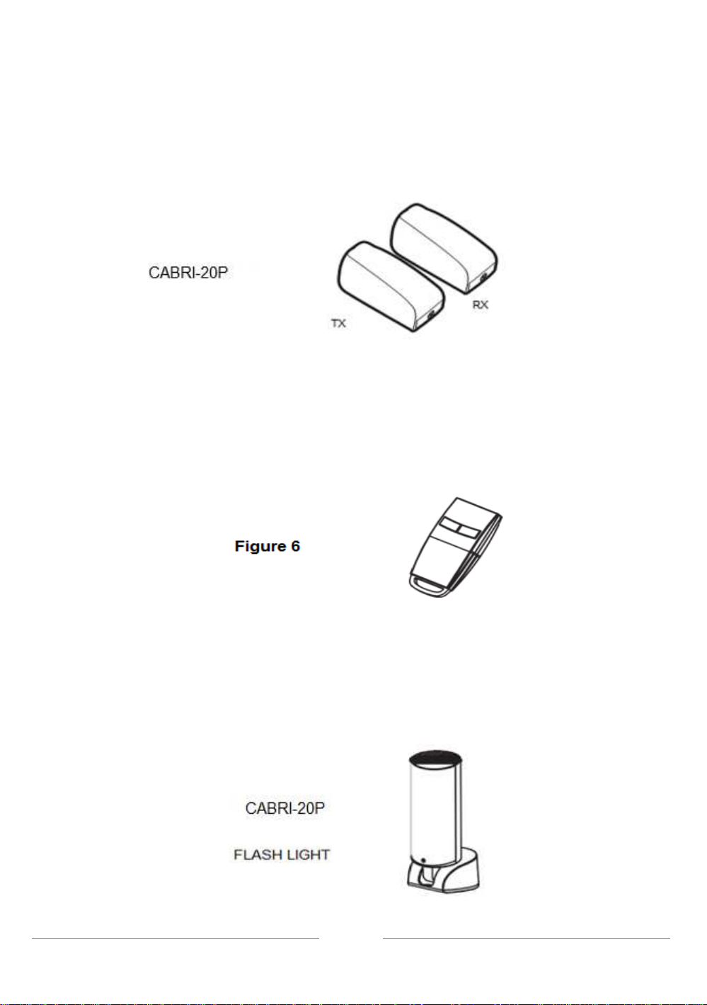
1.3.3 Photocells
The pair of Photocells has to be installed on the wall and connected to the control
panel. The function of the photocells is to detect the obstacles found on the optical
axis between the transmitter (TX) and the receiver (RX).
Figure 5
1.3.4 Radio Transmitter
Radio transmitter is used for the remote control of the gate movement. To use the
transmitter, press and hold the button for 1 second. There are two buttons on the
transmitter and (A) button is “open-stop-close mode” and (B) button is “pedestrian
mode”.
1.3.5 Flashing Light
Flashing light is controlled by control box and blinks when the gate is moving.
The flashing light stops blinking when the gates finish opening or closing
Figure 7

INSTRUCTIONS CABRI-20P
Page 7
SWING GATE OPENER
1.3.6 Electric Latch and Stopper
Electric latch is used to lock the gate and it has to be used with stopper and installed
on the master gate.
Figure 8
LIST OF SMALL PARTS
M8*25L hex bolt 3pcs
M8 self locking nut 3pcs
Key
2pcs
2) Installation:
2.1 Notes of Motors in Operation
The
CABRI-20P
gate openers are applicable to per leaf of 2.5 meters in width and
200 kg in weight which can be opened up to 110 degrees primarily for residential use;
where the performance shall be influenced by the factors such as gate dimension,
weight and climate that the driven torque is necessarily to be adjusted properly
.
2.1.1 Tools in Installing
Please make sure all tools and cables are ready and conform to the industrial
safety standard before installation. Please refer to Figure 9.
Figure 9
INSTRUCTIONS CABRI-20P
Page 8
SWING GATE OPENER
2.1.2 Motors, Components and Its Installation in Illustration
The installation procedure of CABRI-20P may be changed due to Various
accessories and quantities installed. The basic wiring diagram is shown in Figure 10.
No wiring cables for accessories are supplied with CABRI-20P.
Figure 10
2.2 Power Connection
CABRI-20P is required to connect two cores wires, which requires very low
voltage that no professionally trained personnel is required in installation; however, the
users are advised to read the installation manual carefully before going for it. After
getting to know all accessories and their positions, suggest starting from cable conduit
arrangement to prevent the cables from being broken or damaged.
2.2.1 Notes for Power Connection
1. The installation of power supply cable to the motor should be carried out
by a qualified professional electrician.
2. The power supply cable of the motor should be equipped with short circuit
protection and leakage protection.
3.
Please make sure to shut off the power before going installation or maintenance
.
2.3 Installation
2.3.1 Preparation for Motor Installation
CABRI-20P is not applicable to a gate which is inefficient or unsafe, neither to
solve the defects due to incorrect installation nor poor maintenance.

INSTRUCTIONS CABRI-20P
Page 9
SWING GATE OPENER
1)
Make sure the weight and dimensions of the gate conform to the operation range of
CABRI-20P. Don’t use CABRI-20P if the specifications do not meet the
requirements.
2). Make sure the gate structure conform to the criteria of automatic operation and
force regulations.
3). Make sure there is no serious friction existing in the opening or closing travel of the
gate leaves.
4). Make sure the gate is at horizontal level that the gate will not move aside at any
position.
5). Make sure the gate can bear the impact of the motor torque when it is installed on
any hole of the bracket which the surface is sufficiently sturdy.
6). Make sure the photo sensors are installed on flat surfaces to ensure the two ends of
receiving and transmitting corresponded to each other.
7). Check the dimensions of the motors as below.
Figure 11
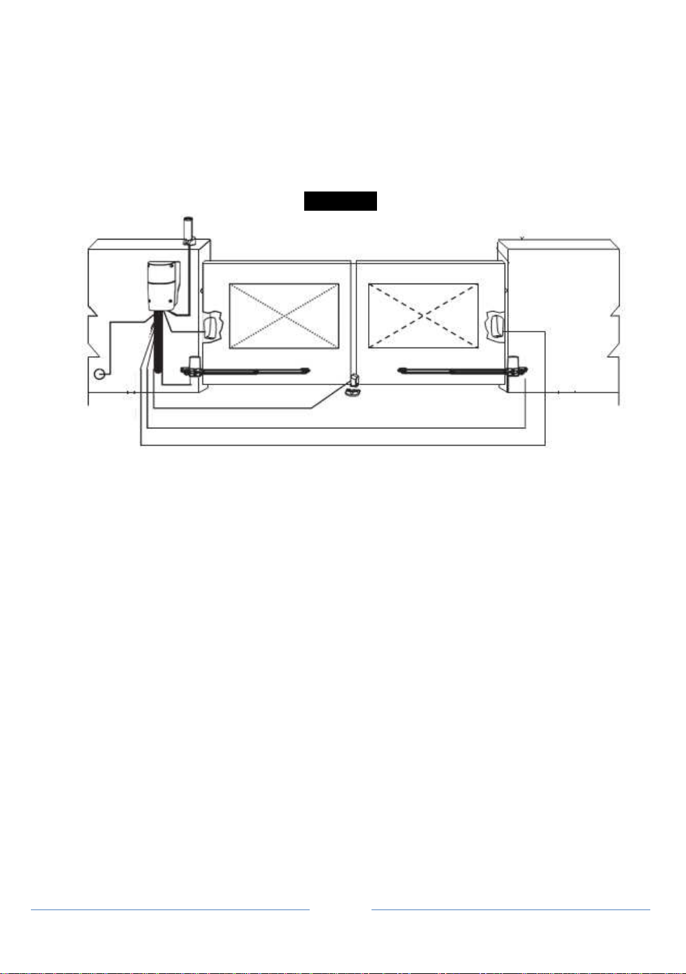
8). Make sure to leave enough space when the gate is opening
Figure 12(Aerial View)

INSTRUCTIONS CABRI-20P
Page 10
SWING GATE OPENER
9).
If the gate is OPENED OUTWARD, please leave at least 70mm between the post
brackets and the gate.
Figure 13 (Aerial View)
Figure 14 (Aerial View)
10) Using the leaf-opening angle as criteria to make sure all criteria in Figure 15
can be met.
Figure 15

INSTRUCTIONS CABRI-20P
Page 11
SWING GATE OPENER
11). “C” value is 139mm.
12). “D” can be measured from the gate easily.
13). “A” = “C” + “D”
14). The value of “B” can be calculated from the value of “A” and the leaves opening
angle. Ex. If “A”=160mm with the leaves opening angle of 100 degrees, then the
value of “B” is approximate 190mm.
**Please make sure “B” and “A” are similar or the same in value that the leaves
can be operated smoothly, also to reduce the burden of the motor.
2.3.2 Installation of The Gear Motors
1. Choose the correct dimensions of the motors and position to be installed.
2. Check if the mounting surface the brackets to be installed is smooth, vertical
and rigid.
3. Arrange the cable conduit for power supply cable of the motors.
4. Loosen the screw and remove the cover of the motor as shown in
Figure 16
.
5. Place the leaves in the closed position
.
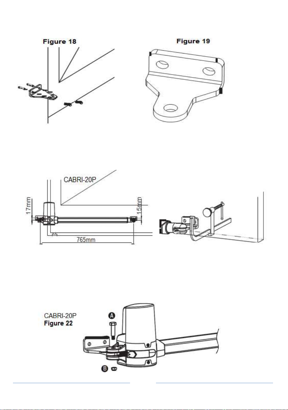
6. Refer to the distance of “B” in
Figure 17
,place the rear plate in the correct position on
the mounting surface. Inspect if the distance is proper as shown in Figure 22 i.e. the
position the front plate of the motor to be installed.
7. Place two post brackets on the surface to be installed and mark the drilling points,
then drill minimum diameter of 8mm holes by four on the mounting surface to be
installed and fasten up the brackets with screws and washers.
8. Please make sure the front plate is completely installed horizontally.
INSTRUCTIONS CABRI-20P
Page 12
SWING GATE OPENER
.
9. Refer to Figure 20,the distance between front plate of the motor and rear plate is
798mm (CABRI-20P), the difference in height is 15.5mm (CABRI-20P).
10. Clamp and fix the motor front plate on the door temporarily
.
Figure 20 Figure 21
11. Lift up the motor and insert the screws into the front plate.
12
.
Lift the motor overhead and push the gate to the end until the screw holes of the
motor end matches the holes on the rear plate. Fasten the motor to the rear plate
with the bolt as shown in Figure22.
INSTRUCTIONS CABRI-20P
Page 13
SWING GATE OPENER
13. Fasten the nut tightly and loosen it for half round for motor supporting in rotating.
14. Fasten the motor front end to the front plate with the bolt (A) and nut (B) tightly.
Fully tighten the screw.
15. Use appropriate key to release the gear motor.
16. Try to push the released gate and make sure the motor can be manually moved
easily.
17. Make sure the motor front plate can be fastened on the gate to be installed
permanently.
18. Use appropriate Key to fasten the gear motor again.
19. Loosen the plastic nut under the power cable of the motor end, and penetrate the
power cable through the nut and screw it up.
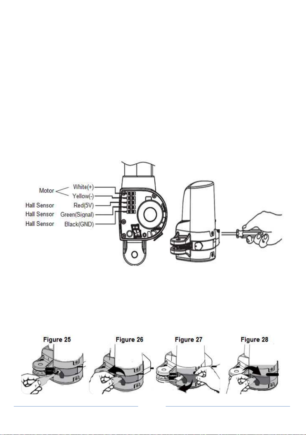
20. Connect the motor power cable as shown in Figure23.
22. Close the gear motor cover by tightening the two screws as shown in Figure24
Figure 23 Figure 24
CABRI-20P
23.
Gear Motor Release
1). Insert the release key to the release slot Figure25.
2). Turn the release key anti-clockwise Figure26.
3). Pull out the release bar Figure27.
4). Turn the release key clockwise to fix the release bar, the release bar has to be in
pulled out position when you turn the release key clockwise Figure28.
5). The turning direction will be reversed for right motor
INSTRUCTIONS CABRI-20P
Page 14
SWING GATE OPENER
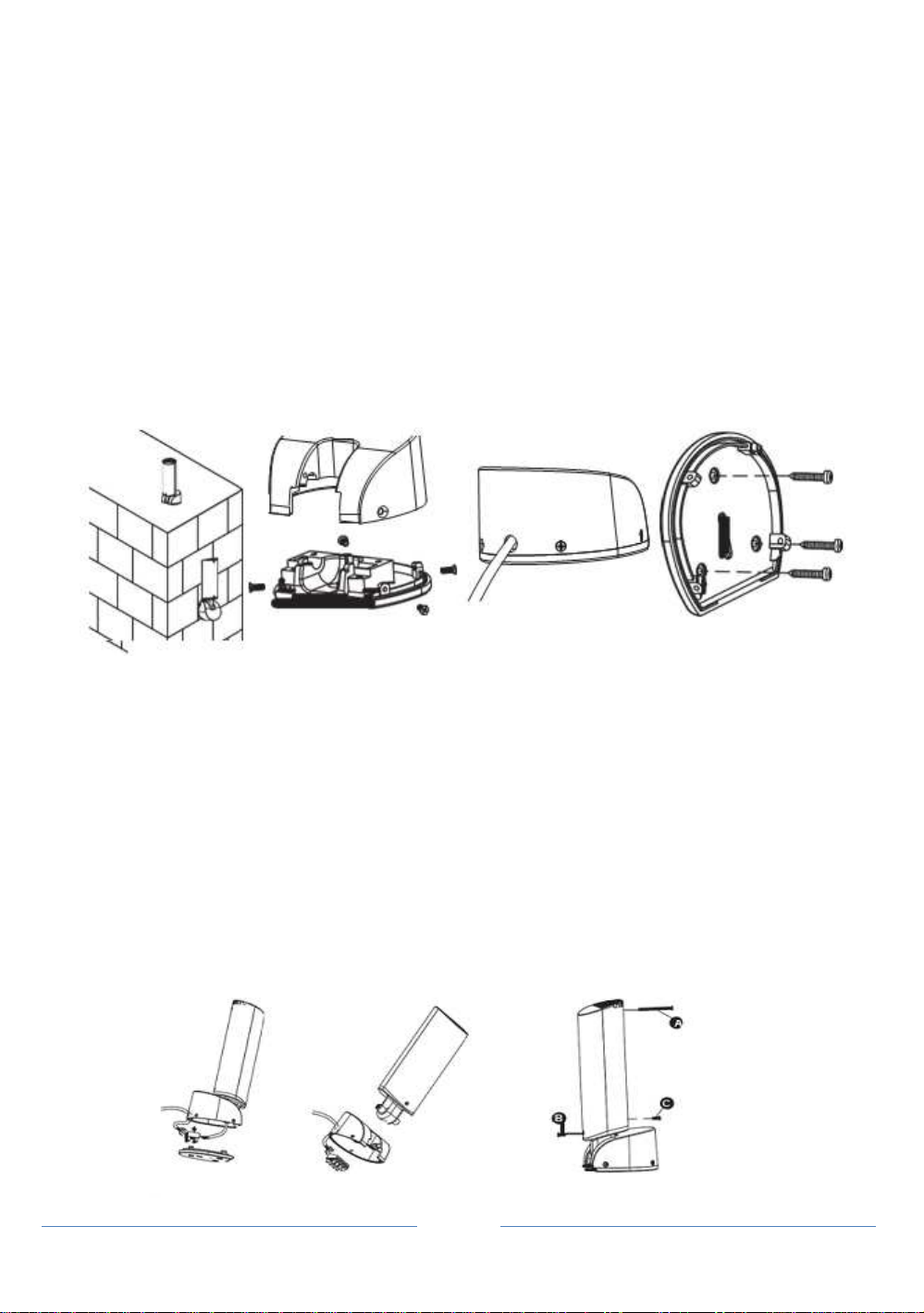
2.3.3 Flashing Light
1) Decide the installation position of the flashing light. The flashing light has to be
installed near the gate and easy to be seen by users and passersby. The flashing
light can be installed horizontally or vertically.
Figure 2.3.3 (1).
2) Unscrew the four screws on the light base and separate the base with the bottom
as shown in
Figure 2.3.3 (2).
3) Connect the wires and penetrate the wires into the hole of the base.
Figure 2.3.3 (3).
4) Drill the holes in the wall and fix the bottom to the wall by three screws.
Figure 2.3.3 (4)
Figure 2.3.3(1) Figure 2.3.3(2) Figure 2.3.3(3) Figure 2.3.3(4)
5). Connect the two wires of the light to the PCB terminals and place the wires into the
conduit if necessary. See Figure 2.3.3 (5).
6). Tighten the four screws back on the light base. Figure 2.3.3 (6)
7). Replacing the bulb set. See Figure 2.3.3 (7)
7.1) Unscrew the flashing light wires from the PCB terminals and make sure the
power of the light is off.
7.2) Release the three screws (A) (B) (C) of the flashing light cover.
7.3) Separate the flashing light cover and replace the bulb set with a new one.
7.4) Tighten the three screws (A) (B) (C) of the flashing light cover.
Figure 2.3.3(5) Figure 2.3.3(6) Figure 2.3.3(7)

INSTRUCTIONS CABRI-20P
Page 15
SWING GATE OPENER
2.3.4 Photocells
1). Open the cover Figure 2.3.4 (1) .and connect wires Figure 2.3.4 (2).
2). Mounted the receiver and transmitter on the proper position Figure 2.3.4 (3)
3). Ensure there are no obstacles between receiver and transmitter. For optimal
efficiency, the receiver and transmitter should be properly aligned.
4). Power-up the photocells and make sure the LED light on receiver and
transmitter are ON
Figure 2.3.4(1) Figure 2.3.4(2)
Figure 2.3.4(3)
2.3.5 Electric Latch and Stopper
1.
Stopper
:
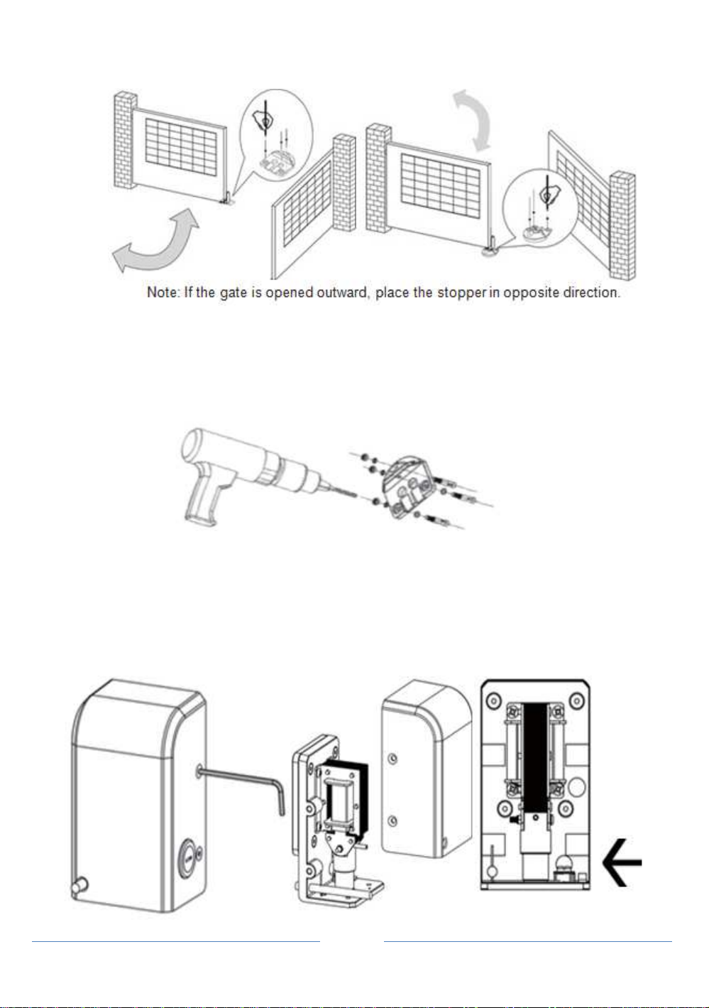
1). Before installing the stopper, please make sure the gates are in close positions and
the surface to be installed is flat.
2). Place the stopper on the ground using the bottom as reference, and mark the 3
drilling points. See
Figure 2.3.5 (1)
for the gate opened inward.
See
Figure 2.3.5 (2)
for the gate opened outward.
INSTRUCTIONS CABRI-20P
Page 16
SWING GATE OPENER
Figure 2.3.5(1) Figure 2.3.5(2)
3
). Drill the 3 marked points, and then securely attach the stopper to the ground with
screws and washers.See
Figure 2.3.5
(3)
Figure 2.3.5(3)
2. Electric Latch. (If the gate is opened outward)
1)
If the gate is opened outward, please change the spring inside and screw it in the
different place. See Figure 2.3.5(4),
Figure2.3.5(5),
Figure2.3.5(6), Figure2.3.5(7)
Figure 2.3.5(4) Figure 2.3.5(5) Figure 2.3.5(6)
Unscrew the screws Take the casing off The location of the spring

INSTRUCTIONS CABRI-20P
Page 17
SWING GATE OPENER
Figure 2.3.5(7)
Change the spring and screw in different place
2
). Weld the back plate of the electric latch to the surface on the master gate.
See
Figure 2.3.5(8).
Please avoid melting the wires by the heat of the fixed plate
Figure 2.3.5(8)
For the gate opened inward
Figure 2.3.5(9)
For the gate opened outward
3). The gap between the bottom of electric latch and the stopper should be less than 7mm.
Figure 2.3.5(10).
4). Connect the wires of the electric latch to the terminal LAT (+) and LAT (-) on the PCB.
Figure 2.3.5(10)
For the gate opened inward.
Figure 2.3.5(11)
For the gate opened outward
INSTRUCTIONS CABRI-20P
Page 18
SWING GATE OPENER
AUTOGLIDE CABRI-20P
3) Control Box
Control Box Installation
1. Decide the installation position of control box first, it is suggested to be installed
near the gate and should be protected from possible damage. Be aware of the
motor cable length before deciding the installation position.
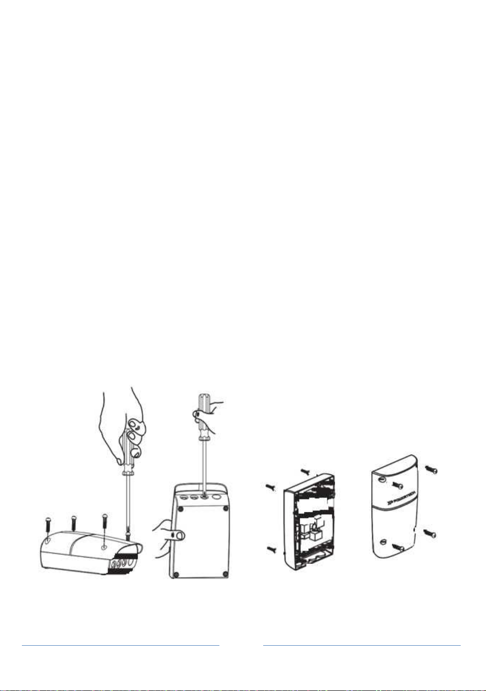
2.
Remove the cover by unscrewing the four screws on the cover.
Figure 1(1)
.
3. Use a screwdriver to puncture the holes beneath the bottom of the control box.
Figure
1(2).
4. Secure it on the wall.
Figure
1(3).
Figure 1(1) Figure 1(2) Figure 1(3)

INSTRUCTIONS CABRI-20P
Page 19
SWING GATE OPENER
5. Wiring Connection:
Prepare all the wires of the accessories beforehand and connect the wires to the
gear motors and accessories on the PCB as shown in
Figure 1(4)
.
All of the wiring
connections of the accessories are not requested to distinguish the positive (+) and
the negative (-) polarity.
1). Flashing light: Connect the two wires from the flashing light to the terminal
L+ and L- on the PCB.
2). Electric Latch: Connect the two wires from the electric latch to the terminal
Lo + and Lo- on the PCB.
3). Gate openers: Refer to Figure 1(4) and connect the wires separately to the
terminals on the PCB.
Motor 1:
Connect the motor wire (White +) to the terminals Mo1 +, and
(Yellow -) to the Mo1-.
Motor 2:
Connect the motor wire (White +) to the terminals Mo2 +, and
(Yellow -) to the Mo2 -.
Notes:
For gates opened outward.
Motor 1:
Connect the motor wire (Yellow -) to the terminals Mo1 +, and
(White +) to the terminals Mo1-.
Motor 2:
Connect the motor wire (Yellow -) to the terminals Mo2 +, and
(White +) to the terminals Mo2
-.
4). Photocells:
See Figure
1(4)
(A) installed one set Photocell to FO1, SW3 setting as below:
3. Ph_conn1 > OFF and 4. Ph_conn2 > ON
(B) installed one
set
Photocell
to
FO2,
SW3
setting as below:
3. Ph_conn1 > ON and 4. Ph_conn2 > OFF
(C) installed two sets Photocell, SW3 setting as below:
3. Ph_conn1 > OFF and 4. Ph_conn2 > OFF
(D) No Photocell has been installed, SW3 setting as below:
3. Ph_conn1 > ON and 4. Ph_conn2 > ON

INSTRUCTIONS CABRI-20P
Page 20
SWING GATE OPENER
Figure 1(4)
Table of contents
Other Autoglide Gate Opener manuals


Popular Gate Opener manuals by other brands


HySecurity
HySecurity HTG 320-8 Installation and maintenance manual

GiBiDi
GiBiDi ART5000 Instructions for installation

Sun Power
Sun Power XP Series owner's manual

Grant's Automation
Grant's Automation SD series installation manual

RIB
RIB SUPER 8000 FAST L1-CRX manual

Chamberlain
Chamberlain LA100 owner's manual


