Autoglide Magro-500 J User manual

Magro-J – Series
Swing Gate Opener
User Manual
www.autoglideglobal.com
2018

Dear users,
Thank you for choosing this product. Please read the manual carefully before assembling and using it.
Please do not leave out the manual if you send this product to a third party.
1. Safety Instruction
Please ensure that the using power voltage matches with the supply voltage of gate opener
(AC110V or AC220V); kids are forbidden to touch the control devices or the remote-control unit.
The remote-control unit is controlled by a single button mode or three button mode (please refer to
the instructions of the remote control in accordance with the actual gate opener type). The indicator
light on the remote-control unit will flicker when the button on it is pressed. Main engine and gate
can be unlocked by disengagement wrench and the gate can move with manual operation after
disengagement.
Please ensure that no one is around the main engine or gate when the switch is operated and it is
usually demanded to examine the stability of installation. Please temporarily stop using if the main
engine needs repairing or regulation.
The installation and maintenance of the products must be carried out by professionals.

2
2. Packing List (standard)
No. Picture Name Quantity
1
Main engine 2
2
Manual release bar 1
3
A
B
C
D
A
B
C
D
Remote control 2
4
Control box 1
5
Wall bracket 4
6
Front mounting bracket 2
7
Connecting bracket 2
8
Mounting screw (short) 2
9
Mounting screw (length) 2
10
Screw M8×25 4
11
Nut M8 8
12
Safety stopper (Optional) 1

3
2. Packing list (optional)
No. Picture Name Quantity
1
Infrared sensor 1
2
0
8
5 6
97
4
1 2 3
Wireless keypad 1
3
Alarm lamp 1
4
Electronic lock 1
5
Storage battery 2
3. Technical parameters
Model Magro - 500 J Magro - 650 J
Power supply 220V/50Hz;110V/60Hz 220V/50Hz;110V/60Hz
Motor power 80W 80W
Gate moving speed 18~22 second per 90 (approx) 18~22 second per 90 (approx)
Max.single-leaf weight 250 Kg 325 Kg
Max.single-leaf length 2.5M 3.0M
Max.piston stroke: 34cm 54cm
Max.force 1500N 1500N
Remote control distance ≥30m ≥30m
Remote control mode Single /Three button mode Single / three button mode
Storage battery (optional) DC24V (4.5AH or 9.0AH) DC24V (4.5AH or 9.0AH)
Noise ≤58dB ≤58dB
Working duty S2, 30min S2, 30min
Recording of up remote controls
25 25
Frequency 433.92 MHz 433.92 MHz
Working temperature -20°C - +70°C -20°C - +70°C
Package weight 17Kg 19Kg

4
4. Installation
Magro J Series swing gate opener is applicable to single leaf gate weight less than 225/300 kg, and
length of the single leaf swing gate should be less than 2.5m/3m. The drive mode adopts the worm
and worm gear to combine the screw rod transmission. This gate opener must be installed inside
the enclosure or yard for protection.
4.1 Installation drawing
0
8
5 6
97
4
1 2 3
⑦
①
③
④
⑤
②
⑧
⑥
Figure 1
① Control box; ② Gate opener; ③ Gate; ④ Alarm lamp (optional);
⑤ Infrared sensor (optional); ⑥ Stopper; ⑦ Remote control; ⑧ Wireless keypad (optional);
4.2 Size of main engine and accessories
4.2.1 Size of main engine
190
970Max
620Min
104
Magro - 500 J

5
190
1370Max
820Min
104
Magro – 650 J
Figure 2
4.2.2 Size of mounting plate
40
2× 8.5
70
8.5
17.5
43
Front mounting bracket Wall bracket
φ
Figure 3
4.3 Installation steps
4.3.1 Preparation before main engine installation
a) Before installing the door opener, please confirm the correct installation of the door to ensure that
the door can be easily manually operated, and the door safety stopper can effectively prevent the
door to continue moving.
b) Install the electric lock, the distance between the door bottom and ground should be 40-50mm. If
not install the electric lock, the distance between door bottom and ground should be ≥20mm;
c) The main engine recommended mounting height is about 300 ~ 800mm from the ground, and
make sure there are reliable fixed points for mounting brackets.
Cable
In order to ensure the normal operation of the door opener and protect the cable from damage,
please use PVC pipe laying motor, power cable, and control cables, and separate two PVC pipes to
lay (motor and power cable) and (control cable), respectively.
6
Mounting brackets
In order to install the Magro - 500 J / Magro - 650 J main engines firmly, recommend to use the
expansion screws to fix the mounting brackets.
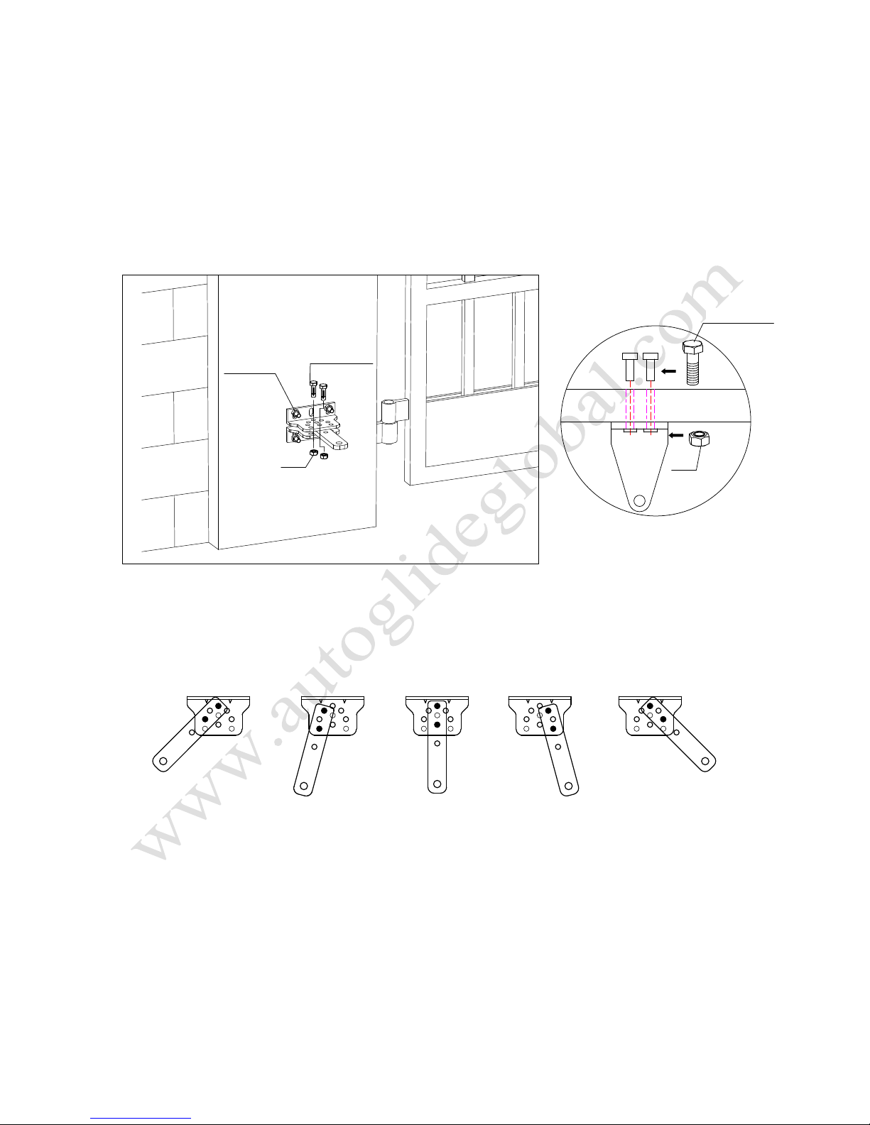
4.3.2 Accessory
a) Before installing the main engine, install the wall bracket on the wall, then fix the connecting
bracket, and install the front mounting bracket on the door.
Note: Please detect by gradienter before fixing, to ensure that the front mounting bracket
and the connecting bracket in the same level.
Expansion screw Hexagon screw
Nut Nut
Hexagon screw
Figure 4
b) The connecting bracket and the wall bracket can be connected according to different conditions,
as shown in figure 5.
Figure 5
c) Users shall prepare power cables for the control box and main engines, according to different
installation environment; the power cable of the control box is not less than 3 cores, and the motor
cable with 2 cores. If you need to install electric locks, infrared sensor, alarm lamp, external button
switch and other external equipment, please increase corresponding the embedded wire, and the
sectional area of electric lock cable core shall not be lower than 1.5mm², others shall not be lower
than 0.5mm². The length is determined by the user of according to the situation in the installation
site.
7
Note: The pipe outlet should be facing down to avoid rain water entering the pipe along the cable.
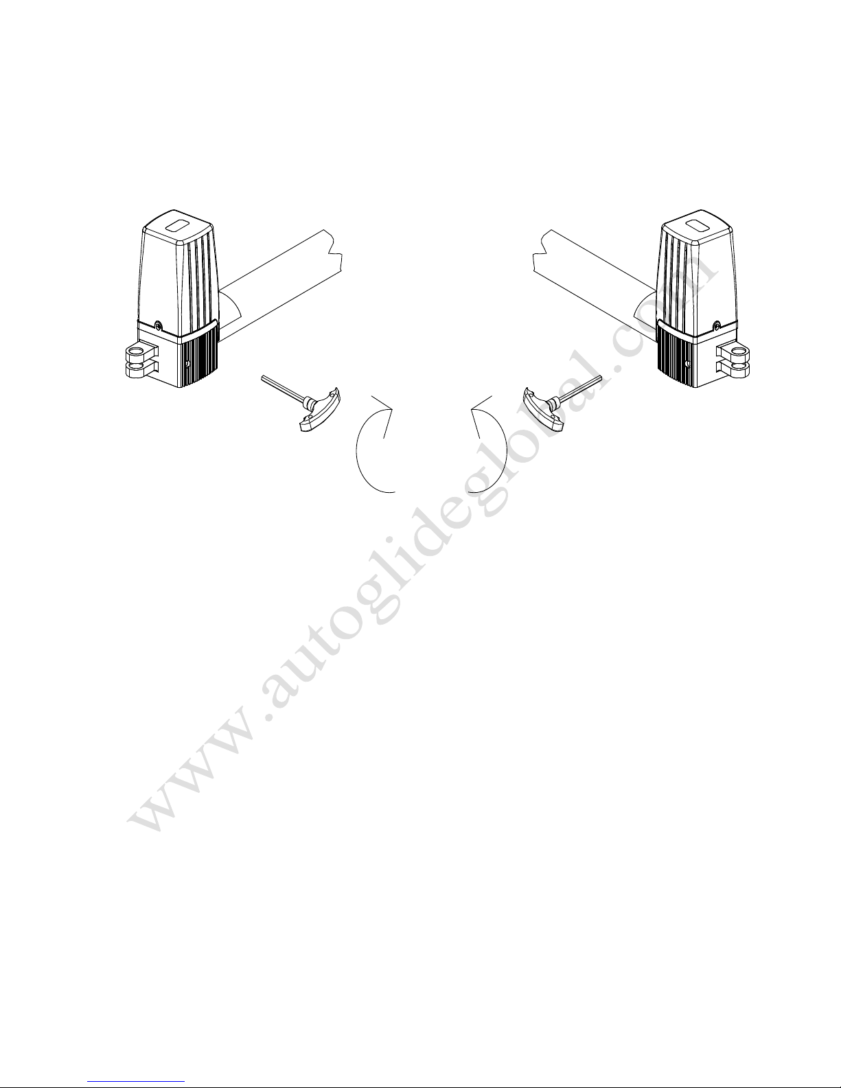
d) Before the installation, please unlock the main engine. Method: Remove the cover, insert the
manual release bar, rotate the bar until the release, as shown in Figure 6, then turn the telescopic
arm to make it easily stretch.
Left engine Right engine
Figure 6
4.3.3 Main engine installation
As shown in Figure 7, the tail of the main engine and the connecting bracket are fixed together
through the installation of screws, and then manually adjust the telescopic arm to the appropriate
length, and finally fix the telescopic arm connector and the front mounting bracket with the
installation screws. Pull the door after the completion of the installation to ensure the entire process
flexible without jamming.

8
Mounting screw (length)
Nut Mounting screw (short)
Nut
Figure 7
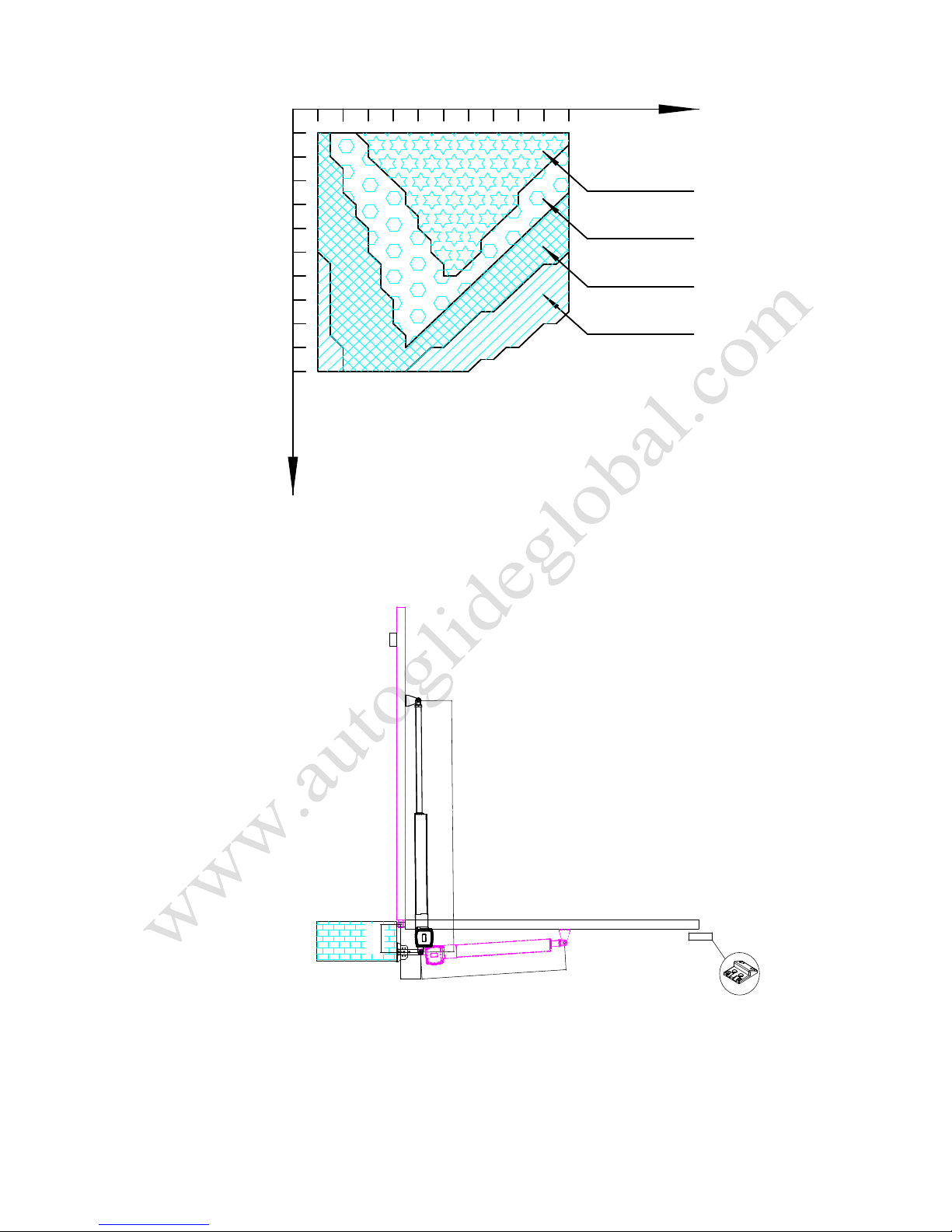
Installation direction: door open facing inward (Magro - 500 J)
Note:Note: SafetySafety stopperstopper mustmust bebe installedinstalled
L
K
L=620+5L=620+5
K
<
620+340620+340
A
B
Figure 8

9
100 110 120 130 140 150 160 170 180 190 200
100
110
120
130
140
150
160
170
180
190
200
Max 90°
Max 100°
Max 110°
Max 120°
mmmm
B
A
Figure 9
Note: Value B must be close to or equal to the value A to obtain the best mechanical
advantage.
Installation direction: door open facing outward (Magro - 650 J)
L
K
L=620+5L=620+5
K
<
620+340620+340
A
B
Note:Note: SatetySatety blockblock mustmust bebe
installed,installed, isis proviedprovied byby installerinstaller
Note:Note: SafetySafety stopperstopper mustmust bebe installedinstalled
Figure 10

10
100 110 120 130 140 150 160 170 180 190 200
100
110
120
130
140
150
160
170
180
190
200
Max 90°
Max 100°
Max 110°
Max 120°
mmmm
B
A
Figure 11
Note: Value B must be close to or equal to the value A to obtain the best mechanical
advantage.
Installation direction: door open facing inward (Magro - 500 J)
L
K
L=820+10L=820+10
K<820+540820+540
A
B
Note:Note: SafetySafety stopperstopper mustmust bebe installedinstalled
Figure 12
11
100 120 140 160 180 200 220 240 260 280 300
100
120
140
160
180
200
220
240
260
280
300
Max 90°
mmmm
A
B
Max 100°
Max 110°
Max 120°
Figure 13
Note: Value B must be close to or equal to the value A to obtain the best mechanical
advantage.
Installation direction: door open facing outward (Magro - 650 J)
L
K
L=820+10L=820+10
K<820+540820+540
A
B
Note:Note: SatetySatety blockblock mustmust bebe
installed,installed, isis proviedprovied byby installerinstaller
Note:Note: SafetySafety stopperstopper mustmust bebe installedinstalled
Figure 14

12
Max 120°
mmmm
B
A
Max 110°
Max 100°
Max 90°
100
120
140
160
180
200
220
240
260
280
300
100 120 140 160 180 200 220 240 260 280 300
Figure 15
Note: Value B must be close to or equal to the value A to obtain the best mechanical
advantage.
4.3.4 Size of control box
Figure 16
210
275
127.5

Warnings
·To ensure safety, when door open facing outward, the safety block must be installed at the OPEN
limit position to prevent the door opening angle from exceeding the machine range; the safety
stopper must be installed at the CLOSE limit position, to make two doors stopping at the CLOSE
limit position accurately (as shown in figure 10, 14). When door open facing inward, the safety
stopper must be installed at the CLOSE limit position (as shown in figure 8, 12).
·Before installing the main engine, make sure that the main engine and components are in good
mechanical performance and that the door can be operated manually.
·One control unit can control driving one main engine or two main engines.
·Earth leakage circuit breaker must be installed where the gate movement can be seen, and the
minimum mounting height of control box is 1.5m to protect it from being touched.
·After installation, please check whether the mechanical property is good or not, whether gate
movement after manual unlocking is flexible or not, and whether the infrared sensor (optional) is
installed correctly and effectively.
4.3.5 Control board wiring
M1M2
AlarmAlarm lamplamp
MainMain engineengine 1
ElectricElectric locklock
+24VDC+24VDC
CommonCommon terminalterminal
InfraredInfrared protectionprotection
15VDC15VDC
DoorDoor closeclose buttonbutton
Open/Stop/closeOpen/Stop/close controlcontrol buttonbutton
SingleSingle doordoor openopen buttonbutton
+
24VAC24VAC
BattaryBattary
TestTest buttonbutton
LearningLearning buttonbutton
-
IRIRCOMCOM+PWR+PWR
DCDC24V24V
LIGHTLIGHT MOTORMOTOR 1 MOTORMOTOR 2 LOCKLOCK 15V15V
P.SWP.SW P.SWP.SW
OPOP
CLCL 1
2
CN5CN5
C11C11
U4U4
78L0578L05
TESTTEST
REVREV
LEARNLEARN
+BATTERY-+BATTERY-
U3U3
PK300DCM-2PK300DCM-2
POWERPOWER
ACAC
MOTOR1MOTOR1 MOTOR2MOTOR2
VR1VR1 VR2VR2
ACAC FUSEFUSE
LED8LED8
LED6LED6
LED7LED7
OPOP
CLCL
VX1VX1
LED4LED4
OPOP
LED3LED3
CLCL
VX2VX2
LED2LED2
LOCKLOCK
RY8RY8
LED7LED7
D20D20
IN5408IN5408
C8C8
U2U2
6.2V6.2V
IC2IC2 F1F1
RX1RX1
15A15A
LM317LM317U6U6
8A8A
FUSEFUSE
6A106A10
D14D14
RY6RY6
RY4RY4
10UF10UF
C4C4
10UF10UF
C4C4
RY1RY1RY1RY1RY2RY2
470UF470UF 470UF470UF
C2C2 C1C1
C3C3
78157815
10A10A
U1U1
LED1LED1
6A106A10
D12D12
6A106A10
D13D13
6A106A10 6A106A10
D11D11 D10D10
RY5RY5
U5U5 78127812
Q2Q2 Q3Q3
SENSORSENSOR
CN4CN4CN3CN3CN2CN2
AN1AN1
MainMain engineengine 2
CommonCommon terminalterminal
CommonCommon terminalterminal
Figure 17

Wiring instruction:
POWER AC terminal 24VAC alternating current power.
+
BATTARY
-
terminal Storage battery.
8P terminal:
LIGHT Alarm lamp (24VDC);
MOTOR 1 Main engine 1;
MOTOR 2 Main engine 2;
LOCK Electronic lock (24VDC).
CN2 terminal
:
+
PWR Power supply for fittings +24VDC;
COM Common;
IR Input of infrared sensor (N.C.).
CN3 terminal: Power supply for fittings 15VDC.
CN4 terminal: Signal input of gate close control button;
Control button common terminal.
CN5 terminal: Open/Stop/Close/Stop loop control button;
Control button common terminal;
Single door opening button.
Transformer wiring
TransformerTransformer inputinput
220VAC/110VAC220VAC/110VAC
TransformerTransformer outputoutput 24VAC24VAC
REVREV
+BATTERY-+BATTERY-
POWERPOWER
ACAC
MOTOR1MOTOR1 MOTOR2MOTOR2
VR1VR1 VR2VR2
ACAC FUSEFUSE
F1F1
RX1RX1
15A15A
LM317LM317U6U6
8A8A
FUSEFUSE
6A106A10
D14D14
C3C3
78157815
10A10A
U1U1
LED1LED1
D12D12D13D13
U5U5 78127812

15
DIP switch
Dial Function
1 Door closing delay function:
ON: Enabled - Motor 2 is 5 seconds delay to close the door than Motor 1;
OFF: Disabled.
2 Door opening status:
ON: Enabled - Motor 1 and motor 2 conduct 0.5-second close action before open
the door;
OFF: Disabled.
3 Single / Double door mode:
ON: Single door mode;
OFF: Double door mode.
4 /
5 Automatic close function:
5 ON 6 ON——Automatic close time is 60s;
5 ON 6 OFF——Automatic close time is 10s;
5 OFF 6 ON——Automatic close time is 5s;
5 OFF 6 OFF——No automatic close function.
6
Adjusting knob
Adjust the sensitivity of meet obstacle: clockwise adjusting VR1 can reduce sensitivity of obstacle of
the motor 1; clockwise adjusting VR2 can reduce sensitivity of obstacle of the motor 2.
Infrared connection
Infrared photocell function: In the closing process, when infrared ray of the infrared sensor is
covered, the gate will open immediately, to protect user and property security.
The distance between photocell receiver and photocell emitter should be not less than 2 meters,
otherwise will affect the induction of the photocell.
If connect the infrared photocell, please remove the short connection between IR and COM on the
CN2 terminal.

16
ComCom OutOut
SETSET NCNC
InfraredInfrared receiverreceiver connectingconnecting
- +
- +
InfraredInfrared emitteremitter connectingconnecting
IRIRCOMCOM+PWR+PWR
LOCKLOCK
15V15V
P.SWP.SW P.SWP.SW
OPOP
CLCL 1
2
CN5CN5
TESTTEST
CN2CN2 CN3CN3
LED7LED7
D20D20
IN5408IN5408
SENSORSENSOR
Figure 19
Adjustment and operation
Remote control operation
Remote control is single button mode, one same button on the remote control to circularly control
the main engine OPEN/STOP/CLOSE/STOP.
OPENOPEN
CLOSECLOSE
STOPSTOP
A
B
C
D
Figure 20
17
Add extra remote control (remote control learning): Remove the upper cover of main engine;
press the learning button S1 on the control board, and indicator light LEARN will flash once and
then go out; press the same button on the remote control twice, the LEARN flashes repeatedly and
then goes out; remote control learning is succeed. At most 25 remote controls can be learned.
Delete remote control: Delete remote control that have been learned; press the learning button
S1 and LEARN will be on; loosen the button until LEARN is off. This indicates that all remote
controls that learned previously have been deleted.
Note: Unlock the door opener, move the door to the middle position, reversely rotate the manual
release bar to lock, electrify and then press TEST button after relay restoration, the door would
automatically operate once, LED4 LED6 on the control panel is the door-opening indicator light that
shows green; LED3 LED6 is the door-closing indicator light that shows red. If the opening-closing
direction is incorrect, the direct-current motor wire could be exchanged to alter the moving direction
of the electrical machine.
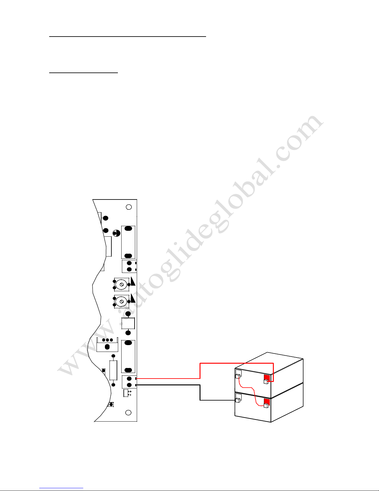
Battery connection:
REVREV
+BATTERY-+BATTERY-
POWERPOWER
ACAC
MOTOR1MOTOR1 MOTOR2MOTOR2
VR1VR1 VR2VR2
ACAC FUSEFUSE
F1F1
RX1RX1
15A15A
LM317LM317U6U6
8A8A
FUSEFUSE
6A106A10
D14D14
C3C3
78157815
10A10A
U1U1
LED1LED1
D12D12D13D13
U5U5 78127812
StorageStorage batterybattery
Figure 21

18
Solar panel connection:
CHARGECHARGE LOADLOAD BATTERYBATTERY
+ - + - + -
+
-
+
-
SolarSolar
panelpanel
SolarSolar chargercharger
StorageStorage batterybattery
REVREV
+BATTERY-+BATTERY-
POWERPOWER
ACAC
MOTOR1MOTOR1 MOTOR2MOTOR2
VR1VR1 VR2VR2
ACAC FUSEFUSE
F1F1
RX1RX1
15A15A
LM317LM317U6U6
8A8A
FUSEFUSE
6A106A10
D14D14
C3C3
78157815
10A10A
U1U1
LED1LED1
D12D12D13D13
U5U5 78127812
Figure 22
5. Others
5.1 Maintenance
Check whether the gate operates normally every month.
For the sake of safety, each gate is suggested to be equipped with infrared protector, and regular
inspection is required.
Before installation and operation of the gate opener, please read all instructions carefully.
Our company has the right to change the instruction without prior notice.

19
5.2 Troubleshooting
Problems Possible Reasons Solutions
The gate cannot open
or close normally, and
LED does not light.
1.The power is off.
2.Fuse is burned.
3.Control board power wiring
with problem.
1.Switch on the power
supply.
2.Check the fuse, change the
fuse if burnt.
3.Re wiring according to
instructions.
The gate can open but
cannot close.
1.Photocell wiring with problem.
2.Photocell mounting with
problem.
3.Photocell is blocked by
objects.
4.Sensitivity of obstacle is too
high.
1.If not connect photocell,
please make sure that the IR
and COM short circuit; if
connect infrared sensor,
please make sure the wiring
is correct and the photocell is
N.C.
2.Make sure that the
photocell mounting position
can be mutually aligned.
3.Remove the obstacle.
4.Reduce the sensitivity of
obstacle.
Remote control
doesn’t work.
1.Battery level of the remote
control is low.
2.Remote control learning is not
completed.
1.Change the remote control
battery.
2.Re-conduct remote control
learning.
Press OPEN, CLOSE
button, the gate is not
moving, motor has
noise.
Gate moving is not smoothly.
According to the actual
situation to adjust the motor
or the gate.
Leakage switch
tripped.
Power supply line short circuit or
motor line short circuit. Check wiring.
Remote control
working distance is too
short.
Signal is blocked.
Connect external receiver
antenna, 1.5 meters above
ground.
The gate moves to the
middle position to stop
or reverse.
1.Motor output force is not
enough.
2.Sensitivity of obstacle is too
high.
3.Gate meets obstacle.
1.Check whether the
transformer power is normal,
if not, change the
transformer.
2.Adjust the VR1, VR2.
3.Remove the obstacle.
This manual suits for next models
1
Table of contents
Other Autoglide Gate Opener manuals


Popular Gate Opener manuals by other brands


Mighty Mule
Mighty Mule UL325 SERIES installation manual

Genius
Genius MISTRAL Series GUIDE FOR THE INSTALLER

Gatekeeper
Gatekeeper SKC-500DC owner's manual

CAME
CAME Sipario Series Assembly and installation manual

Cardin Elettronica
Cardin Elettronica 200/BL203 instruction manual

King gates
King gates JET XL 230 Installation and use instructions and warnings

Nice
Nice Toona TO4006 Instructions for installation and use

BFT
BFT IGEA-BT Installation and user manual

King gates
King gates Couper 24 Installation and use instructions and warnings

BFT
BFT deimos ultra bt a 400 Installation and user manual

Mighty Mule
Mighty Mule MM272 installation manual

FAAC
FAAC FAACTOTUM manual