Autoglide FERO 600-M User manual

1
Intelligent Remote Control Swing Door Opener
Instruction Manual
Model – Fero 600-M
Control box
Contents Pages
Ⅰ. Summary 2
Ⅰ. Structures & Classification 2
Ⅰ. Main Technical Parameters 3
Ⅰ. Function Characteristics 3
Ⅰ. Operating Methods 3
Ⅰ. Installation Method & Debugging 4
Ⅰ. Maintenance and services 8
Ⅰ. Trouble shooting 8
Ⅰ. Control Board 9
Ⅰ. System S ett in gs
1 1
Ⅰ. A t t e n t i o n s
1 4
Ⅰ. Safety & Cautions
15

2
Ⅰ. Summary
Dear user:
Thank you for selecting of our intelligent remote control swing gate opener! Please
carefully read this Instruction Manual before installation and use.If you have any problem
that you can’t settle during use, please contact your local distributor of our products.
Ⅰ. Structures & Classification
1. Opener structure: as Fig. 1
Fig.1
2.Control and power distribution structure, as shown in Fig.2
Fig.2
3.Classification of gate opener: Inward gate opener and outward gate opener.
4.Classification of Control system: 2- channel 5- line ordinary control system and 2- channel 2- line
wisdom control system.

3
Ⅲ
. Main Technical parameters
Ⅳ. Function Characteristics
1. Single-leaf or double-leaf opening: This function can be activated by pressing button.
2. Control box locking: To avoid unauthorized opening, this function can be activated by
remote control.
3. Automatic detection and protection: The gate opener will automatically stop if any
obstruction is detected during opening; it will return to the original position automatically if
any obstruction is detected during closing.
4. Infrared detection and protection: The gate will automatically re-opened if any passing
vehicle or person is detected during closing.
5. Automatic detection and access control: The gate opener can be connected to card
reader, fingerprint scanner, anti-theft alarm, camera or any other devices for automatic
access control.
6. Gate operating indication: The blue LED light on the gate opener will flash during gate
opening, the red LED light on the gate opener will flash during gate closing, indicating
vehicle and pedestrian that the gate opener is operating, make attention to the
safety.(Optional)
7. Back up battery interface: The gate opener will be automatically switched to storage
battery or solar cell mode upon external power failure.
8. Sequential operation: The gate opening angel and sequence can be set.
Please refer to the Instructions Manual of the control box for the foregoing functions,
interfaces and detailed operating and setting methods.
Ⅴ
. Operating Methods
This gate opener can be controlled electrically and manually. Please remove any
obstructions within the working scope of the gate body and no vehicle or person allowed
access during operation.
(I) Electric control operation
1. Press the button of the control box to realize automatic gate opening, closing or stop.
2. Press the button of the remote control to realize automatic gate opening, closing or
stop.

4
3. The gate access control system can identify and control access automatically.
(II) Manual control operation
1. Manual opening: insert the clutch key into the lock hole and rotate it clockwise to
disengage the clutch (the gate opener in manual mode), then push the gate open by hand.
2. Manual closing: push the gate to near the close position when it is in manual mode, insert
the clutch key into the lock hole and rotate it anticlockwise to engage the clutch(the gate
opener now in electric mode),then push the gate to the lock position by hand.
Fig. 3 Manual and electric switching
Ⅵ
. Installation methods & Debugging
(I) Preparation
1. Check the flexibility of the gate during opening and closing, make sure that the gate does
not bounce back when the gate reaches the open or close limit position.
When the gate is in the close position, the bottom edge of the gate frame shall be at least
25mm above the ground (slightly higher than the stop iron, as shown in fig.4).Make special
adjustments if the gap is less than 25mm.
Fig.4 Heights of Gate Frame and Stop Irons
2. The unevenness of the ground within the working scope of the gate opener.
Fall h=Height of the highest point of the ground- height of the lowest point of the ground.
a) when 0
<
h≤80mm, the fall is normal, choose the standard configuration.
b) when 80mm
<
h≤140mm, the fall is large, choose long configuration.
c) when 140mm
<
h≤300mm, the fall is too large, choose special configuration (dual
slide)

3.
Determination power of the gate op
Measure the width, height, weight of the gate leaf and determine if
motor shall be chose according to the sealing conditions and external environments (e.g.
ground conditions, wind force etc.)
Choose the
model and configuratio
functional requirements.
4.
Bury the wire pipes with reference to the wiring diagram of the power
of the gate opener
(Fig.2) and determine the diameter and number of cores of mu
flexible wires (power cables).
T
wo ways of system configuration
opener and control box:
a) 2-channel 2-line
gate opener
connected via two circuits of two
-
b) 2- channel 5-line
gate opener
connected via two circuits of five
-
If any infrared sensor is added,
please adopt three
sensor to the
control box, and use
transmitting terminal with receiving terminal.
If any card reader is added, please adopt four
to the control box.
Mark the position of the mounting plate on the gate body. Move the mounting plate further
downward by 10-
20mm from the
plate.
In either method, the installing height of the mounting plate
according to the ground smoothness, gate size and weight, hinge flexibility and other
factors.
Note: 1. Fasten the
mounting plate
2.
Keep the mounting plate vertical during
body.
3.
Make one hole on either of the inner sides of the gate on the bottom fame (for entry and
exit of wires) for wires. One flexible sleeve cover the wires shall be used where they go
through the holes.
5
Determination power of the gate op
ener
Measure the width, height, weight of the gate leaf and determine if
ordinary or high
motor shall be chose according to the sealing conditions and external environments (e.g.
ground conditions, wind force etc.)
model and configuratio
n of the gate opener according to
the user type and
Bury the wire pipes with reference to the wiring diagram of the power
distribution
(Fig.2) and determine the diameter and number of cores of mu
wo ways of system configuration
are available according to the conne
ction ways of gate
gate opener
and control box
the gate opener and the control box are
-
core power cables.
gate opener
and control box
the gate opener and the control box are
-
core power cables.
please adopt three
-
core power cables to conn
control box, and use
two-
core power cables to connect the infrared sensor
transmitting terminal with receiving terminal.
If any card reader is added, please adopt four
-
core power cables to connect the card reader
Mark the position of the mounting plate on the gate body. Move the mounting plate further
20mm from the
mark;
this is the actual installing height of the mounting
In either method, the installing height of the mounting plate
shall be appropriately adjusted
according to the ground smoothness, gate size and weight, hinge flexibility and other
mounting plate
with four bolts before mounting plate
installation.
Keep the mounting plate vertical during
installation and bolt or weld it onto the gate
Make one hole on either of the inner sides of the gate on the bottom fame (for entry and
exit of wires) for wires. One flexible sleeve cover the wires shall be used where they go
ordinary or high
-duty
motor shall be chose according to the sealing conditions and external environments (e.g.
the user type and
distribution
system
(Fig.2) and determine the diameter and number of cores of mu
lti-strand
ction ways of gate
the gate opener and the control box are
the gate opener and the control box are
core power cables to conn
ect infrared
core power cables to connect the infrared sensor
’s
core power cables to connect the card reader
Mark the position of the mounting plate on the gate body. Move the mounting plate further
this is the actual installing height of the mounting
shall be appropriately adjusted
according to the ground smoothness, gate size and weight, hinge flexibility and other
installation.
installation and bolt or weld it onto the gate
Make one hole on either of the inner sides of the gate on the bottom fame (for entry and
exit of wires) for wires. One flexible sleeve cover the wires shall be used where they go

Fig.5 Holes on both inner sides of the gate on the bottom frame
4. Fix the gate opener
and connect the
terminal
block of the control box or the color of the plug wire).
Check:
Use the key to switch the gate
forward and backward.
The gate opener shall rise and fall freely with the fluctuation of the ground and no dead
locking, hanging and suspending etc.
5. Installation of the stop iron (
please r
When the gate is in the mode of manual operation, move the gate to the close position
and install the stop iron into the lock hook. Use the key to switch the gate opener to electric
mode and lock it there. Move the stop iron so that the centerlin
the lock hook and mark the position of the stop iron. Drill a hole on the ground and fasten the
stop iron with expansion bolts.
Fig.6
Position of stop iron and
gate(overlook)
Note
a)
The stop iron for the gate leaf that is firstly closed shall be installed first
when the gate has a floor stop. The two stop irons shall be distanced
from each other by 10
b)
The ground where the wheel
ground where the stop irons are rested shall be on the same level when the
gate is at the close position.
c) If
any rubber buffer is to be installed between the pressure plates of the
two leaves, they should be ins
Otherwise, the reliable locking of the gate opener may be affected and the
proper operation of the gate opener may even be disabled.
d) The stop irons
should be
loose
ned or displaced in operation.
6
Fig.5 Holes on both inner sides of the gate on the bottom frame
and connect the
wires (
whose color shall be the same as label of
block of the control box or the color of the plug wire).
Use the key to switch the gate
opener to manual mode and push the gate body
The gate opener shall rise and fall freely with the fluctuation of the ground and no dead
locking, hanging and suspending etc.
please r
efer to the following points):
When the gate is in the mode of manual operation, move the gate to the close position
and install the stop iron into the lock hook. Use the key to switch the gate opener to electric
mode and lock it there. Move the stop iron so that the centerlin
e of the lock hole is aligned to
the lock hook and mark the position of the stop iron. Drill a hole on the ground and fasten the
Fig.7
gate(overlook)
Position
of stop iron and lock hook
The stop iron for the gate leaf that is firstly closed shall be installed first
when the gate has a floor stop. The two stop irons shall be distanced
from each other by 10
-15mm.
The ground where the wheel
s of the gate opener are rested and the
ground where the stop irons are rested shall be on the same level when the
gate is at the close position.
any rubber buffer is to be installed between the pressure plates of the
two leaves, they should be ins
talled before the gate opener is installed.
Otherwise, the reliable locking of the gate opener may be affected and the
proper operation of the gate opener may even be disabled.
should be
installed firmly and they shall not become
ned or displaced in operation.
Fig.5 Holes on both inner sides of the gate on the bottom frame
whose color shall be the same as label of
opener to manual mode and push the gate body
The gate opener shall rise and fall freely with the fluctuation of the ground and no dead
When the gate is in the mode of manual operation, move the gate to the close position
and install the stop iron into the lock hook. Use the key to switch the gate opener to electric
e of the lock hole is aligned to
the lock hook and mark the position of the stop iron. Drill a hole on the ground and fasten the
of stop iron and lock hook
The stop iron for the gate leaf that is firstly closed shall be installed first
when the gate has a floor stop. The two stop irons shall be distanced
s of the gate opener are rested and the
ground where the stop irons are rested shall be on the same level when the
any rubber buffer is to be installed between the pressure plates of the
talled before the gate opener is installed.
Otherwise, the reliable locking of the gate opener may be affected and the
installed firmly and they shall not become

7
Manually open and close the gate to check if the stop irons are properly installed.
a.Push the gate towards the stop iron when the gate is in manual mode, then use the key to
switch it to electrical mode. Push the gate forward and the gate shall be reliably locked.
b.Use the key to switch the gate opener back to manual mode and the gate can be easily
pushed open.
6. Installation of limit magnet for opening
Open the gate to maximum or designed position and retreat it by 200mm.Find the ground
projection of the magnetic switch at the bottom of the gate opener, drill a hole there (Ø22mm)
and bury a magnet leveled with the surface.
Magnet
(IV) Operation and debugging of the electric gate opener
Check if the wiring is properly done and if the voltage meets the requirements before
operation. Use the key to disengage or engage the clutch and check if the gate can be
properly manually opened and closed. Push the gate to the mid-position and engage the
clutch of the gate opener (in electric state).Switch on the mains power and the indicators are
in normal condition.
1. Press the button of the remote control or the control box to open, stop and close the
gate .Observe if the gate opener works in a stable and consistent manner and if it
automatically stops in an accurate manner when the required position is reached.
Otherwise, check it relevant parts are properly installed.
2. Check if the gate moves in the right direction as displayed by the control key. Otherwise,
please correct wiring of the gate opener or motor.
3. Please see the control box’s Instructions Manual for the locking method of keys.
4. Debugging of automatic stop upon obstacle and motor’s loading capacity: it is necessary
to appropriately adjust the potention meter (pressure or resistance) of the control box
according to the gate size, hinge flexibility and ground evenness in order to increase or
decrease the motor’s capacity against resistances.
5. Test methods of automatic stop upon obstacle during opening , and re-open upon
obstacle during closing:

8
a) Apply a counterforce (push or pull with hands) on one leaf during opening and the
gate shall stop opening.
b) Apply a counterforce on one leaf during closing and both leaves shall retreat in the
opening direction. If the motor’s capacity against resistance is set to be too small the
motor may easily stop operation. If it is set to be too big, the protective effects may be
reduced.
6. Please read the control box’s Instruction Manual for the protection time of the gate during
operation. If the protection time is setting too short, the gate will stop automatically
before it reaches the desired position.
7. Please read the control box’s Instruction Manual for setting and time adjustment for
automatic gate closing.
8. The time difference for delayed closing of the gate leaves shall be adjusted according to
the different degrees of opening of both leaves.
9. Please see the Instruction Manual for details about the card reader, infrared protector
and wiring.
Ⅶ
. Maintenance and services
1. The turning parts of the gate opener shall be kept clean and free of any attachments.
2. Frequently clean away the debris in the grooves of the stop iron.
3. Properly lubricate various mechanical moving parts very quarter.
4. Check the power protector and the performance conditions of the backup storage battery
once a month.
Ⅷ
. Trouble shooting

9
Instruction Manual for Control Panel
With soft start and soft stop low speed wisdom type
Product model: Two wires multi-function wisdom type
FERO 600-M
System Methods: remote control and motor integrated with intelligent control
Object: Two channels two wires inward (outward) swing gate opener
Main electrical function: AC, DC type (AC 220V, DC 24V)
Rated power: 180W
Wiring distance: within 30 meters
Remote control distance: within 30-50 meters
Installation: Wall-mounted or desktop
Frequency: 433.92MHZ learning encrypted rolling code type
FERO 600-M Control Board
FERO 600 control board is specially designed according to 24V DC door opener, improved through
D33. With soft start and soft stop low speed function, encrypted remote control ,higher
confidentiality .This system can also optionally available with a back-up battery. When power off,
the battery provides 24V DC power supply to continue working. The battery must be installed
reversely, to avoid wall bracket hit power terminals during installation. As long as the door work

under correct procedure, the circuit board do not need maintenance normally. Install the control
panel as close as possible to the place w
of 1.5mm 2 core wires, to reduce the pressure drop and ensure system
Ⅰ. Function and features:
1. Anti-collision design:
when the door travel is completed, only after press reverse key, t
can be activated so that the over-
travel can be avoided.
2. Motor time protection:
Avoid long time running when travel failure, the time set to 2
seconds.
3. Auto close function: the time
can be adjusted from 1~240
4. Motor strength adjustment
: motor running strength can be adjusted separately. When barrier
blocks, the door stops travel in case of clamping people or object.
5.
Motor opening and closing low speed function:
steady .
6. High security:
remote control with high
anti-interference. Using
the most advanced jump codec technology, more safe and secretive than
the traditional remote control (code number 6561 groups) in the
100 million units, can not be deciphered.
7. Anti-clamping function:
During door
door will automatically stop and run in the opposite direction, to prevent injuries or folder object.
8. LED fault display:
it is easy to carry out maintenance and use through LED screen.
Ⅱ. Red DIP switch setting:
RED DIP switch function of the control panel can be setting as followings
Red DIP switch 1 = Remote control with single key and three key interch
Turn on RED DIP switch 1 to OFF =
individually.
Turn on RED DIP switch 1 to ON = single key cycle, that is which key to be coded that is the key
perform cycle action. For example: use
again=door stop, press open
once more=door close,
this way.
Red DIP switch 2 = Opening sequence function
Turn on RED DIP switch 2 to OFF ,
gate 1 and gate 2 open at the same time.
Turn on RED DIP switch 2 to ON
, gate 2 will open 5 seconds earlier than gate 1.
10
under correct procedure, the circuit board do not need maintenance normally. Install the control
panel as close as possible to the place w
here the door motor is connected with minimum diameter
of 1.5mm 2 core wires, to reduce the pressure drop and ensure system
performance.
when the door travel is completed, only after press reverse key, t
travel can be avoided.
Avoid long time running when travel failure, the time set to 2
can be adjusted from 1~240
seconds.
: motor running strength can be adjusted separately. When barrier
blocks, the door stops travel in case of clamping people or object.
Motor opening and closing low speed function:
this function make the door running more
remote control with high
sensitivity, far
remote distance and strong
the most advanced jump codec technology, more safe and secretive than
the traditional remote control (code number 6561 groups) in the
market. Password
100 million units, can not be deciphered.
During door
closing, when
there are obstacles blocking the
door will automatically stop and run in the opposite direction, to prevent injuries or folder object.
it is easy to carry out maintenance and use through LED screen.
RED DIP switch function of the control panel can be setting as followings
Red DIP switch 1 = Remote control with single key and three key interch
ange:
Turn on RED DIP switch 1 to OFF =
open stop close Single
four keys control
Turn on RED DIP switch 1 to ON = single key cycle, that is which key to be coded that is the key
perform cycle action. For example: use
open to study , press open
= door open,
once more=door close,
press open
again=door open, cycle in
Red DIP switch 2 = Opening sequence function
gate 1 and gate 2 open at the same time.
, gate 2 will open 5 seconds earlier than gate 1.
under correct procedure, the circuit board do not need maintenance normally. Install the control
here the door motor is connected with minimum diameter
performance.
when the door travel is completed, only after press reverse key, t
he motor
Avoid long time running when travel failure, the time set to 2
-240
: motor running strength can be adjusted separately. When barrier
this function make the door running more
remote distance and strong
the most advanced jump codec technology, more safe and secretive than
market. Password
number up to
there are obstacles blocking the
infrared, the
door will automatically stop and run in the opposite direction, to prevent injuries or folder object.
it is easy to carry out maintenance and use through LED screen.
RED DIP switch function of the control panel can be setting as followings
four keys control
Turn on RED DIP switch 1 to ON = single key cycle, that is which key to be coded that is the key
= door open,
press open
again=door open, cycle in

Red DIP switch 3 = Auto close function
Turn on RED DIP switch 3 to OFF
, without auto function.
Turn on RED DIP switch 3 to ON
with auto close function.
With auto close function,
the door will open to the limit,
light flashing in 1HZ, stop indicator light flashing indicate timing of door close.
setting time,
the controller will preform auto close action.
Setting of auto close time:
Turn on RED DIP switch 3 and 8 to ON, press F key, each press 1 second,
how much time you want for the auto close,
turn on RED DIP switch 8 to off, DIP switch 3 position do not change. Whe
action,
the door should open to the limit and detect the signal of open to the limit.
Red DIP switch 4=Low speed function during opening and closing
Motor with low speed function. With low speed function,
place about 1 meter way from door completely closed position. Turn on RED DIP switch 4 to OFF,
close low speed function.
Turn on DIP switch 4 to ON with low speed function.
Red DIP switch 5= Resistance bounce functio
Turn on RED DIP switch 5 to OFF, t
he motor will automatically stop when meet obstructions during
opening or closing.
Turn on RED DIP switch 5 to ON, if meet obstructions during opening the motor
will automatically stop. During closing,
the door to open limit in case of clip person or vehicle.
Red DIP switch 6 = Lock function
Turn on RED DIP switch 6 to OFF, the electric lock do not output voltage during opening.
Turn on RED DIP switch 6 to ON,
during opening,
lock get electric and start action 2 seconds, motor start opening. Electric lock will hold electric 3
seconds and release when the motor start opening.
Red DIP switch 7 = Lock key open singl
Turn on RED DIP switch 7 to OFF,
when press
lock key of the remote control door 2
RED DIP switch 7 to ON , lock key
can
Red DIP switch 8= SET:
Turn on RED DIP switch 8
to ON, start function setting.
During normal working you should turn RED DIP switch 8 back to OFF.
P7 jumper junction: jumper inserted in two pins of LOCK side remote control with lock function,
pressing
"stop" + "lock" at the same time to lock and unlock.
Ⅲ. System setting
1.
Slow speed soft stop adjustment operation:
Low speed Opening and closing can be set in two modes:
time can be set.
11
Red DIP switch 3 = Auto close function
, without auto function.
with auto close function.
the door will open to the limit,
and perform auto close delay, function
light flashing in 1HZ, stop indicator light flashing indicate timing of door close.
the controller will preform auto close action.
Turn on RED DIP switch 3 and 8 to ON, press F key, each press 1 second,
how much time you want for the auto close,
how many times you press F.
After setting,
turn on RED DIP switch 8 to off, DIP switch 3 position do not change. Whe
n perform auto close
the door should open to the limit and detect the signal of open to the limit.
Red DIP switch 4=Low speed function during opening and closing
Motor with low speed function. With low speed function,
the motor will automatic dece
place about 1 meter way from door completely closed position. Turn on RED DIP switch 4 to OFF,
Turn on DIP switch 4 to ON with low speed function.
Red DIP switch 5= Resistance bounce functio
n
he motor will automatically stop when meet obstructions during
Turn on RED DIP switch 5 to ON, if meet obstructions during opening the motor
will automatically stop. During closing,
if meet obstructio
ns the motor will stop first,
the door to open limit in case of clip person or vehicle.
Turn on RED DIP switch 6 to OFF, the electric lock do not output voltage during opening.
during opening,
motor will close and reverse 1 second, electric
lock get electric and start action 2 seconds, motor start opening. Electric lock will hold electric 3
seconds and release when the motor start opening.
Red DIP switch 7 = Lock key open singl
e door function
lock key of the remote control
can open single door that is
lock key of the remote control door 2
(later closed door ) will open solely.
can
not open door solely.
to ON, start function setting.
During normal working you should turn RED DIP switch 8 back to OFF.
P7 jumper junction: jumper inserted in two pins of LOCK side remote control with lock function,
"stop" + "lock" at the same time to lock and unlock.
Slow speed soft stop adjustment operation:
Low speed Opening and closing can be set in two modes:
double leaves opening and closing
and perform auto close delay, function
When reach the
Turn on RED DIP switch 3 and 8 to ON, press F key, each press 1 second,
After setting,
you should
n perform auto close
the motor will automatic dece
leration in
place about 1 meter way from door completely closed position. Turn on RED DIP switch 4 to OFF,
he motor will automatically stop when meet obstructions during
Turn on RED DIP switch 5 to ON, if meet obstructions during opening the motor
ns the motor will stop first,
and then open
Turn on RED DIP switch 6 to OFF, the electric lock do not output voltage during opening.
motor will close and reverse 1 second, electric
lock get electric and start action 2 seconds, motor start opening. Electric lock will hold electric 3
can open single door that is
(later closed door ) will open solely.
Turn on
P7 jumper junction: jumper inserted in two pins of LOCK side remote control with lock function,
double leaves opening and closing

First mode: auto set low sp
eed opening and closing time
After completely install and adjust the motor,(when setting the door should be on the close
position,
this is very important),turn on red DIP switch 8 and 4 to ON,
control panel (or open button of t
he remote control) to open to door,
running.
Open and close double leaves in sequence,
turn on red DIP switch 8 to OFF, buzzer will make a sound,
close time is set automatically by system, door motor will auto decelerate at the position one
meter away from completely close and open.
Second mode: manually set low speed opening and closing time
After completely install and adjust the motor,(when se
position,
this is very important),turn on red DIP switch 8 and 4 to ON,
control panel (or open button of the remote control) to open to door,
running. Open the first door firstly,
running,
motor will slow down quickly.
same. During closing,
motor 2 close firstly, user press stop button of the remo
motor run to proper position,
this position is motor 2 low speed position,
After double leaves run to the close limit,
setting is finished. Motor 1 and motor 2
CL_L (close sequence):motor close sequence adjustment,
TORQUE 1 and TORQUE 2 (motor strength adjustment): clockwise to increase the strength,
anti-clockwise t
o decrease the strength.
MT-
V (low speed strength): adjust motor strength during low speed close.
the strength, anti-clockwise
2. Add Remote controls operation:
R
emote control adopt the latest encrypted
confidentiality and safety. Press white
the control board,
LED 6 indicator light off, release your hand and press
control twice as soon as possible, you will hear
more remote controls, just repeat the above steps. Key points for learning of remote control: 1.the
remote control not too close to the control panel, it is better to press at your back. 2. Press
with
in one second after pressing the
again after finishing study. The controller can be equipped up to 298 remote controls, with the 298
remote control, the first one will be
3. Delete all
the remote controls operation:
Long press white SN2 STUDY button (noted it is the white rectangle button) of the control
board, 8s later, you will hear “DI”,
indicator light change from off to on,
controls deleted.
4. Door close sequence:
motor close sequence adjustment
When the door have floor,
closing angle can be adjusted from 0
5. Strength adjustment 1:
(Torque 1)
Motor 1 running strength adjustment: the running strength can be adjusted by TORQUE
motor will stop when meet big resistance, in case clip person or object.
12
eed opening and closing time
After completely install and adjust the motor,(when setting the door should be on the close
this is very important),turn on red DIP switch 8 and 4 to ON,
and press open button of the
he remote control) to open to door,
motor will automatically
Open and close double leaves in sequence,
after double leaves running to the close limit,
turn on red DIP switch 8 to OFF, buzzer will make a sound,
setting is finished.
Low speed open a
close time is set automatically by system, door motor will auto decelerate at the position one
meter away from completely close and open.
Second mode: manually set low speed opening and closing time
After completely install and adjust the motor,(when se
tting the door should be on the close
this is very important),turn on red DIP switch 8 and 4 to ON,
and press open button of the
control panel (or open button of the remote control) to open to door,
motor will automatically
user can press stop button of the remote control during motor
motor will slow down quickly.
This position is motor 1 low speed position,
motor 2 close firstly, user press stop button of the remo
this position is motor 2 low speed position,
motor 1 is the same.
After double leaves run to the close limit,
turn on red DIP 8 switch to OFF,
buzzer will make a sound,
setting is finished. Motor 1 and motor 2
low speed time during opening and closing is set by user.
CL_L (close sequence):motor close sequence adjustment,
can be adjust between 0
TORQUE 1 and TORQUE 2 (motor strength adjustment): clockwise to increase the strength,
o decrease the strength.
V (low speed strength): adjust motor strength during low speed close.
Clockwise to increase
emote control adopt the latest encrypted
rolling code, can
not be copied
confidentiality and safety. Press white
SN2 study
button (noted it is the white rectangle button)of
LED 6 indicator light off, release your hand and press
lock of the
control twice as soon as possible, you will hear
one sound “DI” and the study is finished. To add
more remote controls, just repeat the above steps. Key points for learning of remote control: 1.the
remote control not too close to the control panel, it is better to press at your back. 2. Press
in one second after pressing the
STUDY
key of the control panel. 3. don’t press the
again after finishing study. The controller can be equipped up to 298 remote controls, with the 298
remote control, the first one will be
invalid (that is cannot used).
the remote controls operation:
Long press white SN2 STUDY button (noted it is the white rectangle button) of the control
indicator light change from off to on,
release set key and remote
motor close sequence adjustment
closing angle can be adjusted from 0
-30s.
(Torque 1)
Motor 1 running strength adjustment: the running strength can be adjusted by TORQUE
motor will stop when meet big resistance, in case clip person or object.
After completely install and adjust the motor,(when setting the door should be on the close
and press open button of the
motor will automatically
after double leaves running to the close limit,
Low speed open a
nd
close time is set automatically by system, door motor will auto decelerate at the position one
tting the door should be on the close
and press open button of the
motor will automatically
user can press stop button of the remote control during motor
This position is motor 1 low speed position,
motor 2 is the
motor 2 close firstly, user press stop button of the remo
te control when
motor 1 is the same.
buzzer will make a sound,
low speed time during opening and closing is set by user.
can be adjust between 0
-10 seconds.
TORQUE 1 and TORQUE 2 (motor strength adjustment): clockwise to increase the strength,
Clockwise to increase
not be copied
, with better
button (noted it is the white rectangle button)of
lock of the
remote
one sound “DI” and the study is finished. To add
more remote controls, just repeat the above steps. Key points for learning of remote control: 1.the
remote control not too close to the control panel, it is better to press at your back. 2. Press
lock
key of the control panel. 3. don’t press the
STUDY key
again after finishing study. The controller can be equipped up to 298 remote controls, with the 298
Long press white SN2 STUDY button (noted it is the white rectangle button) of the control
release set key and remote
Motor 1 running strength adjustment: the running strength can be adjusted by TORQUE
1,

Strength adjustment 2:
(Torque 2)
Motor 1 running strength adjustment: the running strength can be adjusted by TORQUE 1,
motor will stop when meet big resistance, in case clip pers
6. Auto close function setting:
User’s can set the auto function self.
Turn on RED DIP switch 3 to ON,
Turn on RED DIP switch 3 to OFF,
When setting auto close function,
function light flashing in 1HZ.When reach the setting time,
Auto close time can be adjust by auto close potentiometer.
Auto close time setting:
Turn on RED DIP switch 8
one second, after setting,
turn on RED DIP switch 8 back to OFF, and position of switch 3 do not
changed.
Note: Check
the rotate direction of the motor
Make sure that the door work in correct direction after the
Press open
of the remote control,
the door should close.
Close and open state is very important.
will operate in opposition way.
If find
black wire of motor 1 or reverse red wire and
wrong, reverse red wire and black wire of motor 1.
and black wire of motor 2.If both of the motors direction are
wire of motor 1, reverse red wire and black wire of motor2.
IV
. Components for swing gate opener
1. DC power supply
(optional component like power reserve UPS): UPS do not need maintenance,
automatically charging and supply power. During installation, connect UPS plug to UPS interface
of the control panel.
Install fuse of the UPS,
reversely, UPS may burn.
2.
Access code lock use outlet button or inter phone to open the door (card reader optional
accessories,
if added):Connect +12v power interface of the card reader to +12V power interface
of the control board, connect -
12V power interface of the card reader to GND power interface of
the control board,
connect PUSH/ON of the card reader to OPEN interface of the control board
(Noted: Access card reader should be compatible with
PUSH / ON output is a low voltage signal negative output).
3.
Button switch (Far distance button single key cycle function ): This control board with far
distance button control function, when you need to add external button ,connect button
to single key interface and public interface of the control board, button switch perform in this
way:
When the door close:--------------
Open, during opening:
When the door open:--------------
Close, during closing:
4. 12V electric lock interface: when the door is completely closed, 12V DC lock is used to avoid
opened by
force. If want to install electric lock, you must turn on RED DIP switch 6 to ON,
13
(Torque 2)
Motor 1 running strength adjustment: the running strength can be adjusted by TORQUE 1,
motor will stop when meet big resistance, in case clip pers
on or object.
User’s can set the auto function self.
Turn on RED DIP switch 3 to ON,
it is with auto close function.
Turn on RED DIP switch 3 to OFF,
it is without auto close function.
When setting auto close function,
door open to the open limit,
perform auto close delay,
function light flashing in 1HZ.When reach the setting time,
controller perform auto close operation.
Auto close time can be adjust by auto close potentiometer.
Turn on RED DIP switch 8
and switch 3 to ON,
press F key, one press
turn on RED DIP switch 8 back to OFF, and position of switch 3 do not
the rotate direction of the motor
Make sure that the door work in correct direction after the
control board connected to power.
of the remote control,
the door should open. Press close
of the remote control,
Close and open state is very important.
If the direction is not correct,
If find
motor direction is wrong,
only need to reverse red wire and
black wire of motor 1 or reverse red wire and
black wire of motor 2.That is if motor 1 direction is
wrong, reverse red wire and black wire of motor 1.
If motor 2 direction is wrong, r
and black wire of motor 2.If both of the motors direction are
wrong,
reverse red wire and black
wire of motor 1, reverse red wire and black wire of motor2.
. Components for swing gate opener
:
(optional component like power reserve UPS): UPS do not need maintenance,
automatically charging and supply power. During installation, connect UPS plug to UPS interface
Install fuse of the UPS,
pay attention to t
he direction of the plug,
Access code lock use outlet button or inter phone to open the door (card reader optional
if added):Connect +12v power interface of the card reader to +12V power interface
12V power interface of the card reader to GND power interface of
connect PUSH/ON of the card reader to OPEN interface of the control board
(Noted: Access card reader should be compatible with
control board of our co
PUSH / ON output is a low voltage signal negative output).
Button switch (Far distance button single key cycle function ): This control board with far
distance button control function, when you need to add external button ,connect button
to single key interface and public interface of the control board, button switch perform in this
Open, during opening:
-------------------Stop
Close, during closing:
-------------------Stop
4. 12V electric lock interface: when the door is completely closed, 12V DC lock is used to avoid
force. If want to install electric lock, you must turn on RED DIP switch 6 to ON,
Motor 1 running strength adjustment: the running strength can be adjusted by TORQUE 1,
perform auto close delay,
controller perform auto close operation.
press F key, one press
turn on RED DIP switch 8 back to OFF, and position of switch 3 do not
control board connected to power.
of the remote control,
If the direction is not correct,
door
only need to reverse red wire and
black wire of motor 2.That is if motor 1 direction is
If motor 2 direction is wrong, r
everse red wire
reverse red wire and black
(optional component like power reserve UPS): UPS do not need maintenance,
automatically charging and supply power. During installation, connect UPS plug to UPS interface
he direction of the plug,
if it is
Access code lock use outlet button or inter phone to open the door (card reader optional
if added):Connect +12v power interface of the card reader to +12V power interface
12V power interface of the card reader to GND power interface of
connect PUSH/ON of the card reader to OPEN interface of the control board
control board of our co
mpany, that is
Button switch (Far distance button single key cycle function ): This control board with far
distance button control function, when you need to add external button ,connect button
switch
to single key interface and public interface of the control board, button switch perform in this
4. 12V electric lock interface: when the door is completely closed, 12V DC lock is used to avoid
force. If want to install electric lock, you must turn on RED DIP switch 6 to ON,
14
during opening, motor will close and reverse 1 second, electric lock get electric and start action
2 seconds, motor start opening.
Electric lock will hold electric 3 seconds and release when the motor start opening.
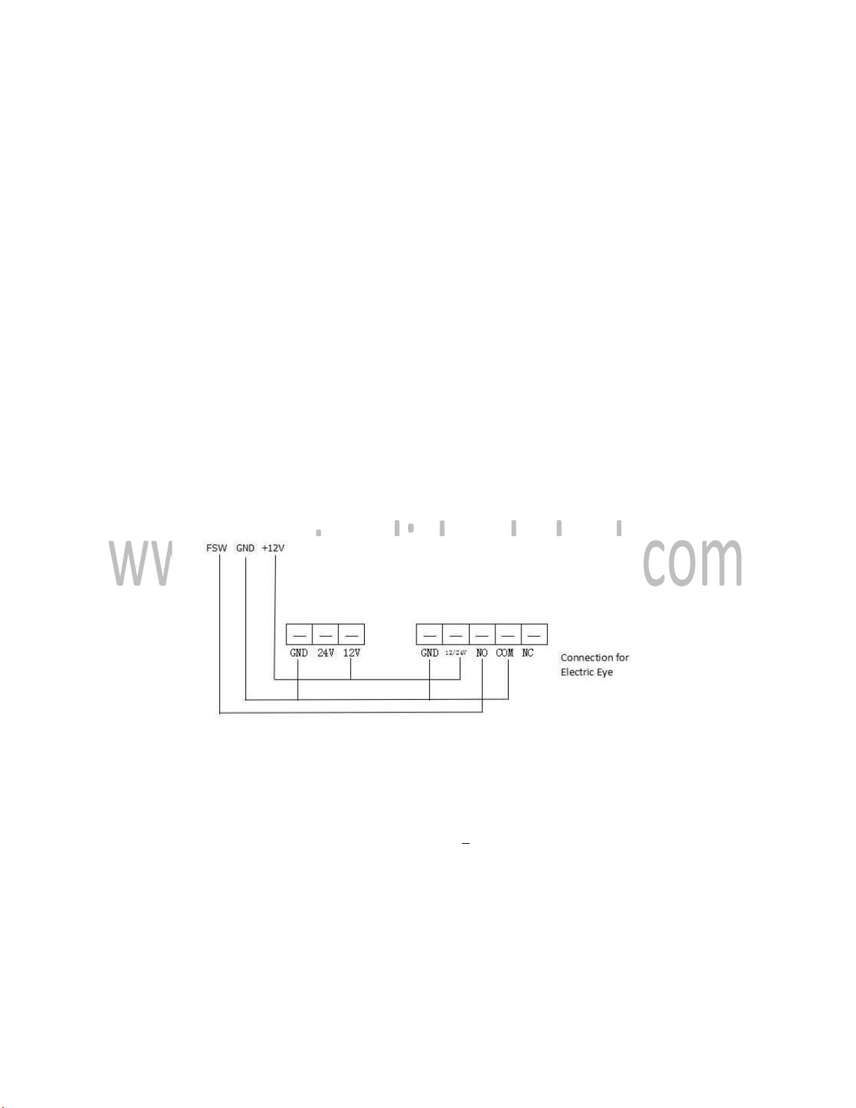
5. Ground sensor or infrared auto close interface: After the car (recommend to add ground sensor)
or person (recommend to add Infrared) passing, motor automatically close, using this interface.
Connect NO (Normal open) of the ground sensor or NO(Normal open) of the infrared to ground
sensor interface of the control board, connect COM of ground sensor or COM of infrared to COM
of the control board..When the door open to the limit, detecting gate opener to the limit, if
ground sensor interface input terminal has normal close signal input, ground sensor will be
function. When car or person leave ground sensor position or infrared position, ground sensor
function, after ground sensor or infrared signal remove 3s , motor star working, performing auto
close. When signal terminal of the ground sensor detect signal input, door will automatically stop
and perform open action, open to the limit. Detect ground sensor signal again, after ground
sensor signal remove, perform auto close.
6. The control board can connected with infrared (connection as following ).
Jump the infrared to normal open, or connect to NO.
During closing of the motor, when photocell has action, the motor will stop 2s and then perform
opening.
Ⅴ. Attentions:
1. The working voltage of the controller is ~220V+ 10%, don’t connect to 380V.
2. The wire buried underground should use thick, double conductor. The three-core shielding
layer of travel switch should be well grounded and not a adapter between. The conducting wire
should be set into PVC tube or pipe and do waterproof processing.
3.The default value is 90 seconds. Use battery of DC12V, 27A for remote control, working life
is one year. Remote control cannot be moisture, crashed. If want to reset password, please refer to
password setting.
4. If the remote distance is short, please check if the mainframe is installed in the position that
is shielded by metal objects or nearby.

15
5. Non-professional personal is forbidden to install the controller and circuit. We are out of
responsibility for any personal safeties caused.
6. If the controller has any quality problem, please send it to agent. If repaired by self, we are
out of responsibility for any loss caused by self-repair.
Safeties & Cautions:
(1)All the operations must be implemented according to the instructions, this is very
important to personal safety.
(2)Please read instructions carefully before installation.
(3)Please keep the instructions properly for future use.
(4)Our product is in strict accordance with the instructions for the design and manufacture.
Any violation of the instructions may damage the product or cause dangers.
(5)Our company is out of responsibility for any operation or use violating the instructions.
(6)Installation must comply with relevant safety standard.
(7)All the machine fittings must comply with national standard related.
(8)Our company is out of responsibility for the consequences caused by user’s ignoring the
process requirements of precision components during operation.
(9)Safety devices (like photoelectric switch, sensor etc.)should be installed to avoid damage.
(10)Any attempts to change the structure of the components is forbidden.
(11)The installation personnel should give detailed operation methods to the users as well
as the regulations under emergency, also the “instructions ”should offered.
(12)Only the operations indicated in INSTRUCTIONS are allowed.
(13)During installation, keep the children and other unrelated person away from the
installation site.
(14)No unsafe factors around the installation site.
(15)Power supply should in accordance with the demand.
(16)Both the door opener and the door body must be well grounded.
Electric leakage as well as short protection device should be equipped.
(17)Before electric control system operate, remove all the barriers within the door covering
area and any vehicles or person are forbidden to pass.
(18)Both the installation position and height of main control box should be proper, do not
be exposed to sunlight and rain, forbidden to let children to operate the remote controller as well
as control panel switch.
(19)If it is necessary to install a outer shield, consider that if it may shield signal of the
remote control.
(20)Keep the remote control away from children in case of accident.
(21)Any attempts to dismantle this machine privately is forbidden, only the professional
technician is allowed to make the maintenance.
(22) Before system maintenance, cut off the power supply, and check if the grounding
system is correct.
www.autoglideglobal.com
Table of contents
Other Autoglide Gate Opener manuals


Popular Gate Opener manuals by other brands


vds
vds UNDER 250 Technical installation manual

Aprimatic
Aprimatic AT 92 T Mechanical installation, Use and Maintenance instructions

CAB
CAB Hydro HD.35 manual

GTO
GTO E-Z GATE installation manual

Pro-Line System
Pro-Line System CS300 operating instructions

Aprimatic
Aprimatic R223 Mechanical installation, Use and Maintenance instructions


