Autoglide VELOCE 80A User manual

INSTRUCTIONS VELOSE-80A
Page 1
SLIDING GATE OPENER

INSTRUCTIONS VELOSE-80A
Page 2
SLIDING GATE OPENER
INDEX
1. Features
2. Technical Specifications
3. Mechanical Installation
4. Manual Release
5. Confirm Direction of Travel
6. Mounting the Sensor Magnets
7. Wiring
8. LED Diagram
9. Wiring For Optional Accessories
10.Remote Control Setting
11.Motor Setting
12.Flashing Light Installation
13.PCB Error Code List

INSTRUCTIONS VELOSE-80A
Page 3
SLIDING GATE OPENER
1.
Features
1. Manufacturer has patent for manual release mechanism. use this feature in case of
Power failure, during installation or maintenance
2. Easy Self-learning feature (Page 9)
3. Commercial power & solar energy power source can be connected at the same time
4. Over current immediate stop function (A0~ A1/B0~B1)
5. Adjustable time of fast speed & slow speed (A2~A5/B2~B5)
6. Adjustment of force during fast speed & slow speed (A6~A7/B6~B7)
7. Auto close function with adjustable closing time delay
8. Optional electric lock connection facility
9. Single or dual swing
10. Use Max up to 50 sets of remote controllers
11. Dc 24v backup battery (optional)
12. Flashing Light AC 220V/110V & DC 24V (optional)
13. Optional Device: DC 24V gate lock, photocell, extensional receiver box.
2.
Technical Specifications
Electrical
Operating voltage DC 24V
Electronic Controller Microcontroller Based
Safety Detection Over current detection
Safety Barrier Infrared Beam Sensor(Optional)
IP Rating IP57

INSTRUCTIONS VELOSE-80A
Page 4
SLIDING GATE OPENER
Mechanical
Model VELOCE 80A
Max Gate weight 800Kg
Motor speed 1800rpm
Gate moving speed 13m/min
Gate Limit type Magnetic Limit Switch
Operating Distance > 50m Frequency : 433.92 MHZ
Remote Control Mode Close/open/Stop/Pedestrain Open
Auto Close Time 0~ 99 sec (Adjustable)
Noise < 65Db
Product actual Size 29*22*23cm
Temperature -15 degree C to + 55 degree C
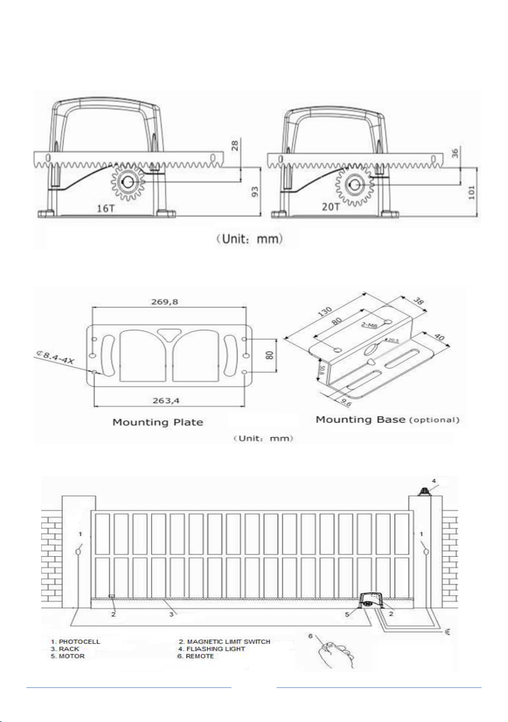
3. Installation
Motor Dimension
INSTRUCTIONS VELOSE-80A
Page 5
SLIDING GATE OPENER
Gear & Rack Installation
Mounting plate/ Base Dimension
Installation Diagram
INSTRUCTIONS VELOSE-80A
Page 6
SLIDING GATE OPENER
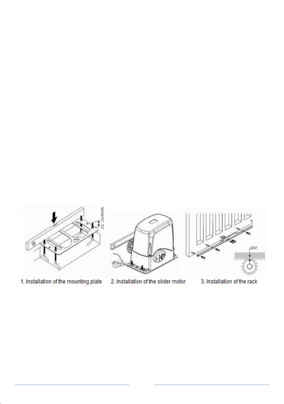
Motor & Rack Installation
1. Reserve a place for the mounting plate
2. Arrange all necessary electric wire in advance
3. Fix the bolt onto the mounting plate, make the threaded portion 25-35 mm higher than
the plate, lock up the plate with nuts
4. Pour cements on the ground, put the mounting plate in place before the cements
solidified. Make sure the mounting plate is in level and horizontal position with the gate.
5. Take off the nut from the bolt, put the slider motor onto the plate, make sure there is
20mm space between the gear wheel of the motor and the side of the gate, fix the
nuts.
6. Manual release the slider motor (follow steps stated in the manual release page)
7. Fix the rack onto the gate, keep 1-2 mm space between the rack and the gear wheel
8. Move the gate for several times by hand, make sure the rack work well with the gear,
and the gate can move smoothly.
9. Turn the slider motor to the electric mode.
If using mounting base, please refer to the following steps
1. Fix the mounting base with the screws on the ground.
2. Fix the motor on the mounting base and make sure motor gear contrite with the
door side keeping 20mm space, then screwing on the nuts.
3. Manual release the slider motor (Following steps on page 5)
4. Fix the rack onto the gate, keep 1-2 mm space between the rack and gear.
5. Move the gate several times with hand, make sure the rack work well with the gear,
and the gate can move smoothly.

INSTRUCTIONS VELOSE-80A
Page 7
SLIDING GATE OPENER
6. Turn the slider motor to electric mode.
4. Manual Release
Place the key in key slot and position at 12 0’ clock, this will allow the allen key
supplied to fit into the hole, rotate handle 90 degree anti clockwise, The gear can now be
rotated manually. Reverse steps to relock steps to relock drive gear.
*Read all instr ctions f lly before proceeding with initial set p
5. Confirm Direction of Travel
With the gate NOT positioned on top of the motor drive gear, press the open button
on the remote and check if the gear drive is turning in the direction your gate is required
to open.

INSTRUCTIONS VELOSE-80A
Page 8
SLIDING GATE OPENER
Change motor direction:
PCB before 2013 reverse the red+ and black – terminals on the motor Pc board.
PCB after 2013 ref to adjustment setting B3
Make sure power is switched off before doing this step.
6. Mounting the sensor Magnets(Magnetic Limit Switch)
Gate opens and closes when the magnets pass the motor sensor
With the gate motor in manual release: Ref to manual release section. Position gate
in the closed position. Place short magnet onto the plastic grated track and tighten where
gate is required to stop after opening.
With the gate motor in manual release: Ref to manual release section. Position gate in
the open position. Place the tall magnet onto the plastic gear track and tighten where
gate is required to stop after closing.
*Magnet heights may need to be adjusted slightly for sensor to read.
Important ensure motor gear is placed back in to the lock position before proceeding
Warning if you are ensure of this step we recommend you place the magnetic sensor
1 meter in from each end for trailing.
www.autoglideglobal.com

INSTRUCTIONS VELOSE-80A
Page 9
SLIDING GATE OPENER
Control Box Setting
1. Wiring
1
.Power Switch.
2
.Accessories and command device’s terminals.
3.
Indicator.
4.
Function Adjustment Button.
5.
DC Light(Optional).
6.
Buzzer.
7. DC 24v Motor
8.
Output DC 24 (Unstable Voltage).
9.
OV “-“ output.
10.
Output DC 15V stable voltage
(load current can’t be over 500 MA)
11.
Backup Battery (12 v 9 ah x 2 in series).
12.
Connector for Solar Panel/ adaptor
. 13.
Switch
(AC 220V & 110V). 14.
Power Supply
(AC220/110V). 15.
Earthed.
16.
AC Flashing Light
LED DIAGRAM
Power on LED 5 will blink. LED1 Open LED. LED 2 Close LED. LED 5 Power LED.
LED 6 Received signal for remote control LED. LED 7 Pushbutton LED

INSTRUCTIONS VELOSE-80A
Page 10
SLIDING GATE OPENER
2. Wiring for Optional Accessories
Item +15V OP/CS
SENSOR GND STOP CLOSE
SENSOR GND Remarks
Description
Stable
voltage
output
Open
/
stop/
close
Back-up "-" &
"Concentration
line"
Close
Limit
Open
Limit
Normally
opening
signal
"-" &
"Concentration
line"
Extensional
Receiver Box
Keypad
Push button
Photocell
(sender)
Photocell
(receiver)
Magnetic Limit
Switch
INSTRUCTIONS VELOSE-80A
Page 11
SLIDING GATE OPENER
*Instructions for photocell:
During closing, if active the signal of photocell, the PCB will activate opening operation
when photocell sensed the obstacle, the door will be stopped then opened immediately
after remove the obstacles, the door will operate according to the new command
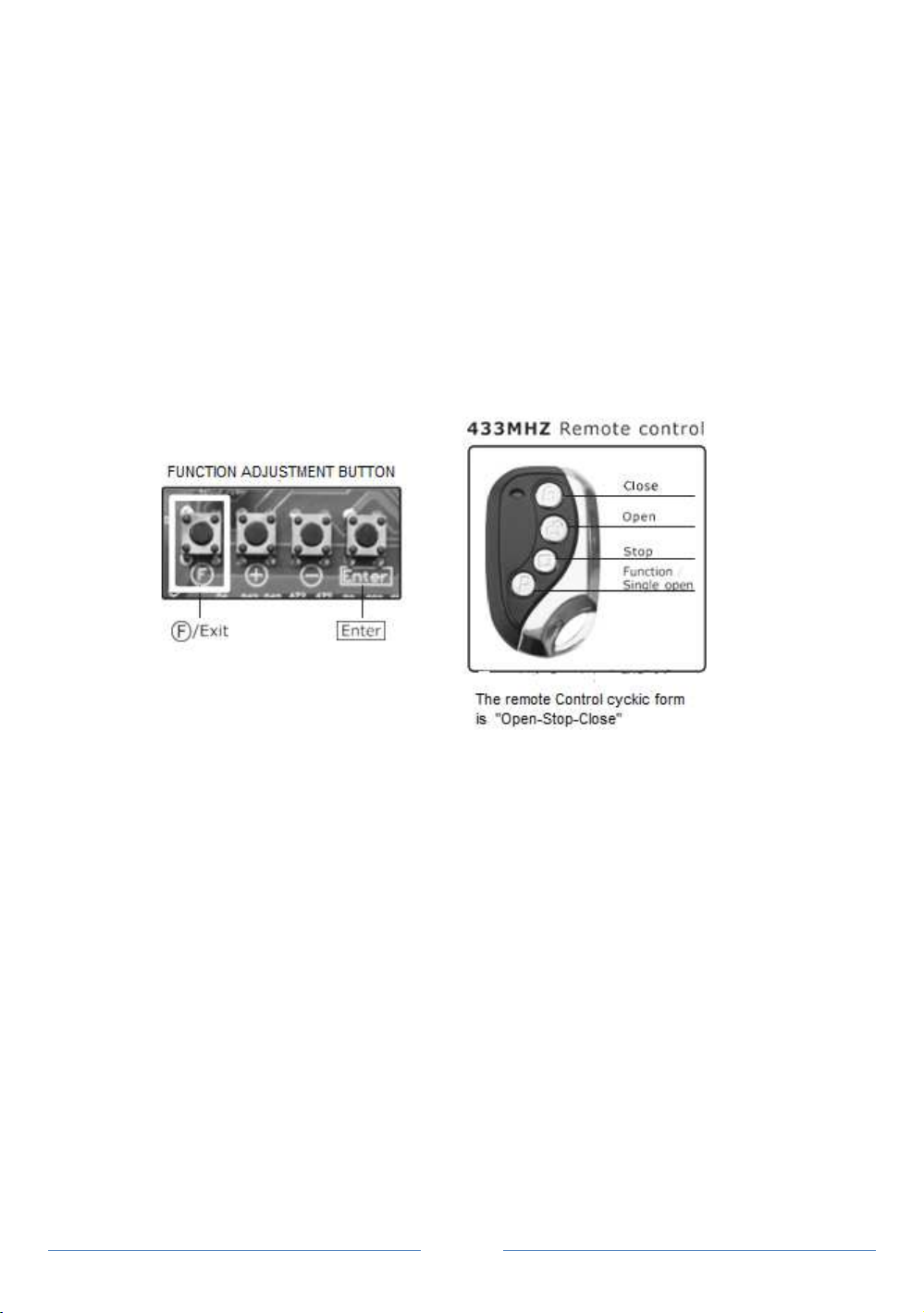
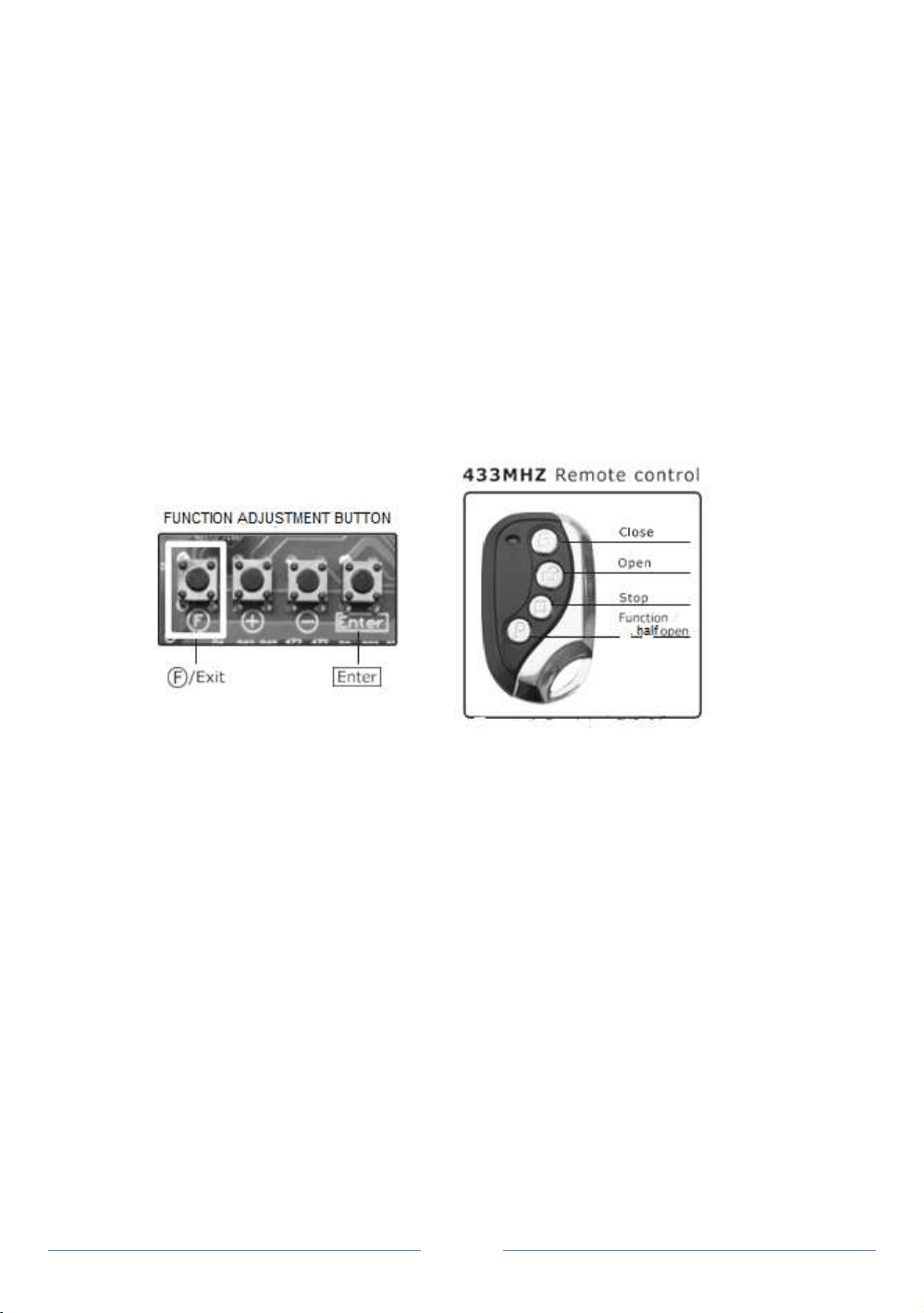
7. Remote Control Setting
7.1 Activating the Remote Control
Press and hold down the “F” button for approximately one second until FF appears
blinking on LED then release button: Pointing the remote at the PC board press any
button on the remote, Remote should now be activated.
* 50 remote controls can be set at most
*Verify the remote control is activated by pressing the remote control button. The LED will
be on/of
7.2 Erasing the code
Press and hold down the “F” button for approximately 1 second Until
“FF” is blinking on LED, release the button then press down the “Enter” button on the PC
board.
8. Total Timer Adjustment for Opening & Closing Gate(Motor Setting)
Gate must be in the closed position before starting the total time for opening gate.
On the PC board hold down the “+” button until “AA” appears on the LED.
Holding down the “P” button & “open” button together on the remote until the indicator on
the PC board is blinking, Release both buttons. The motor will start moving at low sped
then stop once the OPEN magnet reaches the motor sensor.
INSTRUCTIONS VELOSE-80A
Page 12
SLIDING GATE OPENER
(Repeat steps if motor does not move)
Gate in the fully opened position based on your magnet placement.
Holding down the “p” button &”closed” buttons together on the remote until the indicator
on the PC board is blinking, Release both buttons. The motor will start moving at low
speed then stop once the closed magnet reaches the motor sensor.
(Repeat steps if motor does not move)
Gate Should now be in the fully closed position based on your magnet placement, Press
down “F” button to exit learn mode. Repeat steps if adjustments are required to the
opening & Closing distance by reposition magnets.
*Please following the steps if no magnetic limit switch,and then Do the Motor Setting
1. Make Sure it has endstop at the gate opening and closing position.
2. Make Sure the gate is at closed position.
3. After Powered on, making the gate move a small distance when you press the “open”
button, then press the “close” button, the gate will move till meeting the endstop.
Reset gate limits memory after power failure
When doing the motor adjustment after power failure or turn off
Press the “open” or “closed” button on the remote, after the motor operate reach to the
ends, the system has been initialized, and the gate operator can work properly again.
If met obstacles and stiopped, it will require to turn off power and start the
procedure above again.

INSTRUCTIONS VELOSE-80A
Page 13
SLIDING GATE OPENER
1. Function Adjustment
(Follow the steps below)
After yo done” Total Timer Adj stment”, we recommend not to change the setting for
A0~ B0. If yo prefer to change, please refer to following steps.
Step 1 : press “f” button ,the indicator will show “C8”
Step 2 : press “+” button, it’ll show in turn
“C9,D0,D1,D2,A1,A2,A3,A4,A5 PRESS “-“ Button, it’ll show reversely
Step 3 : press “F” button after choose the item, the indicator will show numbers
Step 4 : press “+” or “_” button to select levels
Step 5 : press “Enter” button to confirm
Step 6 : press “F” button for return to previous configuration menu.
Item
Name /
Explanation
Setting
Range
Default
Setting
RE
A0
Intermediate Stop Function with slow speed.
This refers to the sensitivity of
gates when
meeting obstacles during slow speed
operation.
0~99
20
Lower setting means
the gates will be more
sensitive to stopping.
A1
Intermediate Stop Function with high speed.
This refers to the sensitivity of
gates when
meeting obstacles during high speed
operation.
0~99
35
Higher setting means
the gates are not as
sensitive to stopping
on hitting an obstacle.
A2
Total Timer/distance setting when opening
gate
0~99
67
Decimal/single digits
(shown on LED display)
A3
07
Tho sands/h ndreds
digits (shown on LED
displa
y
)
A4
Total Timer/distance setting when closing
gate
0-99
67
Decimal/single digits
(shown on LED display)
A5
07
Tho sands/h ndreds
digits (shown on LED
display)
A6
Force of opening and closing - slow speed.
Force adjustment for low speed operating
during open and close.
0~99
42
.

INSTRUCTIONS VELOSE-80A
Page 14
SLIDING GATE OPENER
A7
Force of opening and closing - high speed.
Force adjustment for high speed operating
during open and close.
0~99
99
A8
Deceleration timer/distance setting when
opening gate
0~99
40
A9
Deceleration timer/distance setting when closing
gate
0~99
40
When activated (Option
“1”), the gates can’t be
pushed open.
B0
Force setting for pedestrian opening
0~99
60
B1
Delay activating time for remote control button
( for avoiding mis operation)
0-2
0
If choose “0”, normal
operation
If choose”1” delay 2
seconds then start the
operation
If choose “2”, first press
stop button for 2 seconds,
then close/open button to
activate the operation
B2
Initial self-distance learning-fast start
0-1
0
If
choose”0” ,low speed
learning
If choose “1” ,fast speed
learning when push open
button
B3
Motor Rotation direction setting
0-1
0
If choose”0”, forward
direction
If choose”1”, reverse
direction
C0
Actual display of A2
and A4 Setting
Digital display when
motor start
C1
Actual display of A3 and A5setting
C2
Alarm setting
0-1 0
“0” = cancel
“1” = Armed when gate
closed

INSTRUCTIONS VELOSE-80A
Page 15
SLIDING GATE OPENER
C3
Time Of Auto Close
0-99
0
If choose “0”, the
gate
system will not have auto
closing function
If choose”10” .it means
the gates will
automatically close 10
seconds after completing
its opening
C4
Time of auto close when pedestrian opening
0-99
0
If Choose “0”, the ga
te
system will not have auto
closing function
If choose “10”, it means
the gate will automatically
close 10 seconds after
completing its opening
C5 Pedestrian opening Distance setting 0-99% 30
C6
Full speed opening setting
0-1
1
If choose “0”, linear
acceleration start(soft
start)
If choose”1”, full speed
st
art
C7
LDR (light dependent resistors)setting**
0-99
0
“0” = cancel
“1
-99” = LDR sensitivity
setti
ng
C8
Battery capacity Display
0-99
Below
“30” = Battery
soon will be run out
“99” = fully charged
C9 Reversed terminal for maintainance and
testing
D0 PCB Model Number
PCB Version Display
D1 PCB Software Version
D2 Restore Default Setting 0
“9” = restore
factory
settings

INSTRUCTIONS VELOSE-80A
Page 16
SLIDING GATE OPENER
Battery Maintenance
Before use the backup batteries,please make sure that they are fully charged, it will lead
to wrong operation if it is not fully charged,and need to check or replace the batteries by
qualified person on a regular time basis.
*Recommend to use 2 pcs of 12 v 9Ah Battery connection in series
Flashing Light Installation
PCB
Debug and Error Code List
Item Description
E0 Low speed hampered stop
E1 Fast speed hampered stop
E2 Using limit switch stop
E3 Normal operating without limit switch
E4 Motor running over 2 minutes stop
E5 Hall sensor failure
E6 Pedestrain opening and closing stop
E7 Input Voltage (transformer, battery) less than DC15V
E8 Press “stop” button on remote control
E9 Motor stop working relate to any optional accessories connecting to terminal “OP/CS”
Proprietary Intellectual Property. Do not Distribute without authorization.
All Rights Reserved-Copyright@2015 Autoglide
www.autoglideglobal.com
Table of contents
Other Autoglide Gate Opener manuals


Popular Gate Opener manuals by other brands

DITEC
DITEC ION4 user manual

Linear
Linear SLC Owner's Information

Beninca
Beninca RI.6SF Operating instructions and spare parts catalogue

Viking Access Systems
Viking Access Systems I-770 Installation instructions and safety information

SEA
SEA HALF TANK installation manual

MFZ Ovitor
MFZ Ovitor MDF Series operating instructions

Extel
Extel Umii XC500 quick start guide

Aprimatic
Aprimatic RAIDER 2000 Installation, use and maintenance instructions

DoorHan
DoorHan SHAFT-50 installation manual

Genius
Genius DIABLO GUIDE FOR THE INSTALLER

Genius
Genius falcon m user manual

Mhouse
Mhouse MhouseKit WG2S Instructions for installation and use


