Autoglide CASA-120-O User manual

AUTOGLIDE
Installation Manual and Owner’s Guide
CASA 120
PLEASE READ THE MANUAL CAREFULLY BEFORE
INSTALLATION AND OPERATION
AUTOGLIDE
Installation Manual and Owner’s Guide
CASA 120
-O
PLEASE READ THE MANUAL CAREFULLY BEFORE
INSTALLATION AND OPERATION
Installation Manual and Owner’s Guide
PLEASE READ THE MANUAL CAREFULLY BEFORE

2
Safeties & Cautions:
AUTOGLIDE series Remote Gate Opener need professional technician for the
installation:
(1)All the operations must be implemented according to the instructions this is
very important to personal safety. Improper installation or misuse of the product
might cause series damage to personal and property.
(2)Please read instructions carefully before installation.
(3)Installation and machine fittings must comply with standards related.
(4)Power supply should be consistent with the requirements of the machine and
well grounding. Electric leakage as well as circuit short protection device should be
equipped.
(5)Before system maintenance, cut off the power , and check if the grounding is
well connected
(6)Strongly recommended to install safety devices (such as infrared protection),
and take frequent check to ensure normal work.
(7)Our company is out of responsibility for any operation or use violating the
instructions.
(8)Our company is out of responsibility for the consequences caused by user’s
ignoring the process requirements of precision components during operation.
(9)Our product is in strict accordance with the instructions for the design and
manufacture. Any violation of the instructions may damage the product or cause
danger.
(10)Our company shall not be responsible for safety problems caused by using
fittings that isn’t produced by our company.
(11)Any attempts to change the structure of the components is forbidden.
(12)The installation personnel should give detailed operation methods to the users
as well as the regulations under emergency, also the “instructions ”should offered.
(13)During installation, keep the children and other unrelated person away from
the Installation site.
(14)Before electric control system operate, remove all the barriers within the door
covering area and any vehicles or person are forbidden to pass.
(15)Both the installation position and height of main control box should be proper,
do not be exposed to sunlight and rain, forbidden to let children to operate the
remote control as well as control panel switch.
(16)If it is neces
sary to install a outer shield, consider that if it may shield signal of
the remote control.
(17)
Place the remote control out of the reach of children in case of accident.
(18)
Any attempts to dismantle this machine privately is forbidden, please contact
professional technician.
(
19) Please save the instructions properly for future use.
Product introduction:
Function & Characteristic:
①
Install overheat protector in AC
when the temperature reach rated power after a long time working, in order to extend
the using life of motor.
②
The product has speedy clutch, inset the release key and turn it
re
lease the clutch when power off
②
Machine running smoothly, parking without inertia, accurate position.
remote control as well as control panel switch.
sary to install a outer shield, consider that if it may shield signal of
Place the remote control out of the reach of children in case of accident.
Any attempts to dismantle this machine privately is forbidden, please contact
19) Please save the instructions properly for future use.
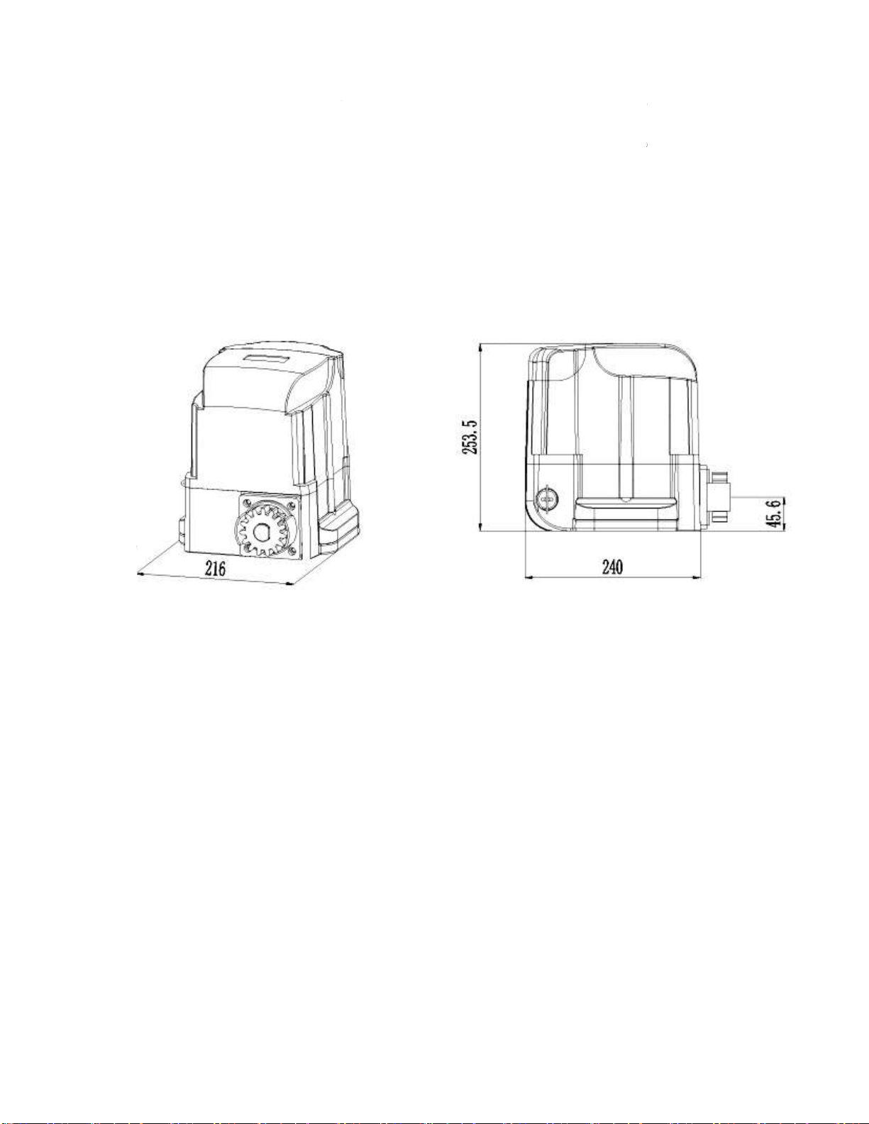
EXTERNAL SIZE (Fig.1)
Function & Characteristic:
Install overheat protector in AC
motor. The motor will cut off power automatically
when the temperature reach rated power after a long time working, in order to extend
The product has speedy clutch, inset the release key and turn it
100 degrees to
lease the clutch when power off
to realized manual operation. (Fig.2)
Machine running smoothly, parking without inertia, accurate position.
sary to install a outer shield, consider that if it may shield signal of
Place the remote control out of the reach of children in case of accident.
Any attempts to dismantle this machine privately is forbidden, please contact
motor. The motor will cut off power automatically
when the temperature reach rated power after a long time working, in order to extend
100 degrees to

Technical parameters:
Packing list
Picture
Screw (M8×30) ,washer, Nut
Model
Power supply
(Vac)
Max. gate weight (KG)
Max
.torque
Rated Power (W)
Tooth number of gear
Overheat protection (
Protection Class
Speed (m/min)
Temperature
Noise
Certification
Fig.2
Name
Quantity
Motor
Instruction Manual
Transmitter
Base plate
Screw (M8×30) ,washer, Nut
Limit switch magnet
CASA 120-
O
(Vac)
phase 110V/220V
~
240V
Max. gate weight (KG)
1200
.torque
35Nm
Rated Power (W)
550W
Tooth number of gear
15
Overheat protection (
℃) 120
Protection Class
IP44
Speed (m/min)
12
(℃) –45
~+
65
≤56dB
Certification
CCC/CE
Quantity
1
1
2
1
4
2
O

Picture
Expansion Bolt(M12×100)
Installation Diagram:
Note: Before installation please check if the motor meets your demand.
Name
Quantity
Bracket for limit switch
Release Key
Expansion Bolt(M12×100)
Note: Before installation please check if the motor meets your demand.
Fig.3
Quantity
2
1
4
Note: Before installation please check if the motor meets your demand.
Installation and Debugging:
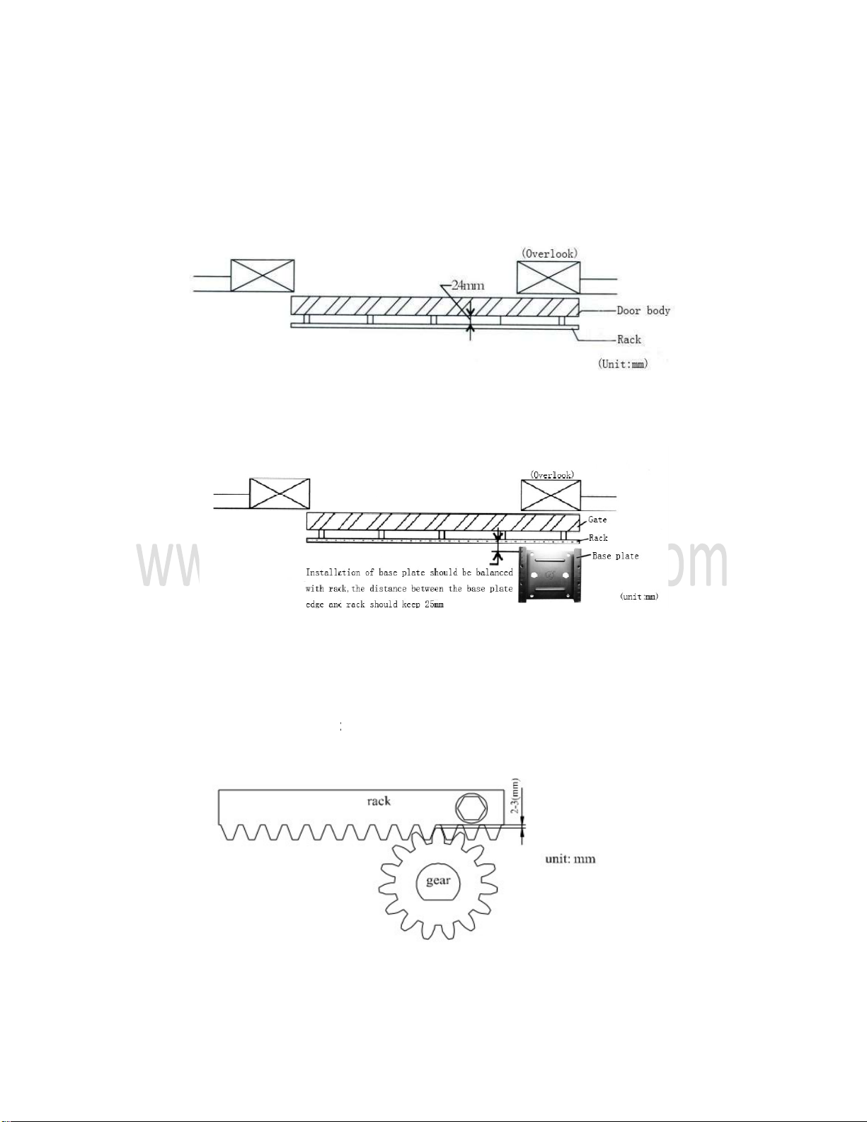
Gear installation
(Distance between gear and door body is
Base installation
:
Rack installation:
(Remark: Please check whether the sliding gate can be mov
before installation rele
ase the clutch with
Warning: There must be a clearance between the rack and gear as Fig. 7, in
case the motor function and manual operation may be
Installation and Debugging:
(Distance between gear and door body is
24mm)
Fig.5
Fig.6
(Remark: Please check whether the sliding gate can be mov
ed smoothly
ase the clutch with
the release key)
Fig.7
Warning: There must be a clearance between the rack and gear as Fig. 7, in
case the motor function and manual operation may be
affected.
ed smoothly
Warning: There must be a clearance between the rack and gear as Fig. 7, in
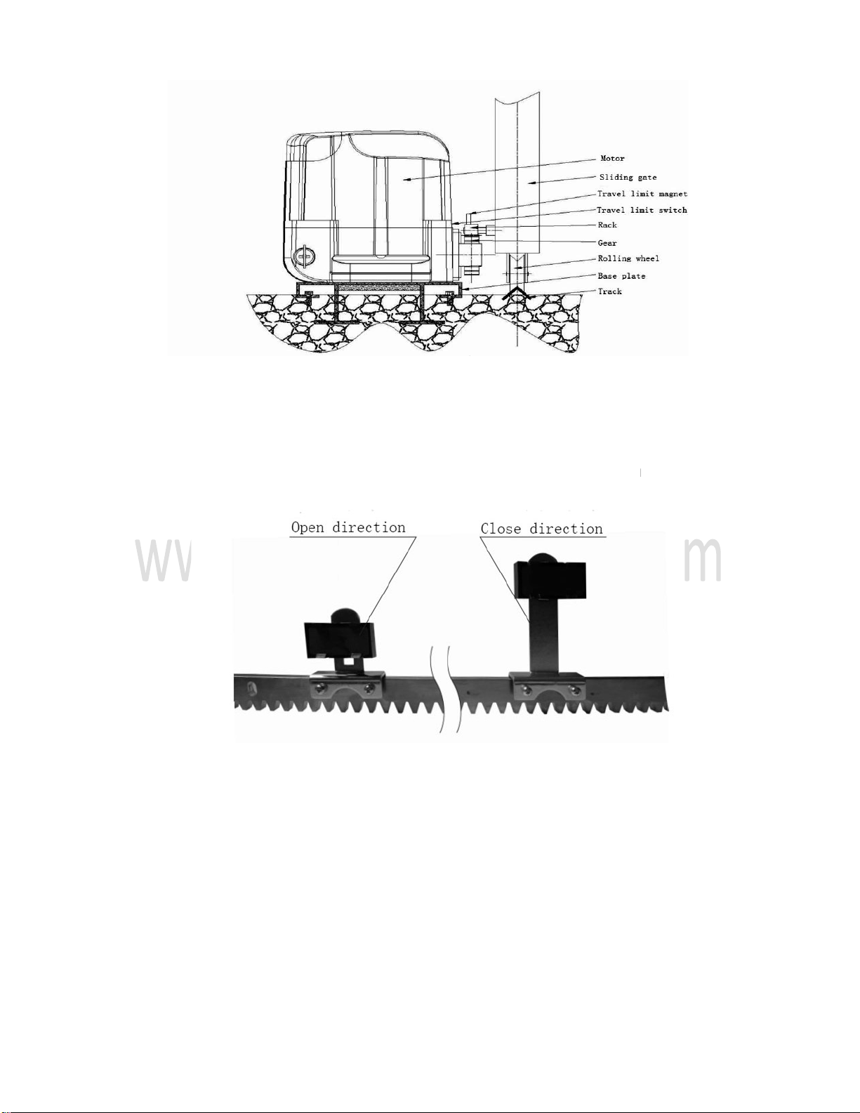
Limit switch bracket installation:
Move the gate manually to the open limit and
then fix t
he magnet bracket at the limit points on the rack. Pay attention to the
direction of limit switch bracket: if it i
Clutch lock:
When the
motor is out of electricity or ha
can use clutch key to release clutch lock then realize manual operation to open or
close the door.
Note: Engage the clutch when the motor resume normal work.
Limit switch bracket installation:
Move the gate manually to the open limit and
close limit,
mark the points on the rack,
he magnet bracket at the limit points on the rack. Pay attention to the
direction of limit switch bracket: if it i
s anti-installed, the motor can
not be positioned .
Fig.9
motor is out of electricity or ha
s faults, can
not work normally, customer
can use clutch key to release clutch lock then realize manual operation to open or
Note: Engage the clutch when the motor resume normal work.
Fig.8
mark the points on the rack,
he magnet bracket at the limit points on the rack. Pay attention to the
not be positioned .
not work normally, customer
can use clutch key to release clutch lock then realize manual operation to open or
Note: Engage the clutch when the motor resume normal work.

Fig.10
Install the electricity plug to an appropriate position according to safety standard.
Install the mounting plate as fig.11.
Note: ensure the base board is in horizontal.
Fig.11
Fix the base plate onto the frame with four expansion bolts (Fig.11) and put the
motor on the base plate, regulate the output gear to match the gear rack, then fasten
the nuts. (fig.12)
Fig.12
Weld the cylindrical nuts for gear rack fixed on proper position in the lower part of
door (Fig. 8), then fasten the gear rack onto the cylindrical nut by bolts or welding.
Regulate the washer behind the base plate base to make the gear match the rack.
(Note: the distance between gear and gear rack should keep1-2 mm)
The limit way of this model is through electrical magnetic limit switch. Please follow
fig. 7 and fig. 9 to install fixed-plate for limit magnetic steel.
Installation of fixed-plate for limit magnetic steel: use clutch key to release clutch like
fig.10.
Move the gate manually to the open limit and close limit, mark the points on the rack,
then fix the magnet bracket at the limit points on the rack, then close clutch for
automatic control. Regulate the position of fixed plate for limit magnetic steel till the
door can open and close properly, and fasten the fixed-plate for limit magnetic steel
finally.
Warning:
Maintenance operations and repairs can be only performed by qualified
technicians. Our company will not bear any legal liability for non-technicians operations.

USER GUIDE:
6-
1 User need to have a regular check whether the door is sliding smoothly,
add lubrication grease on the sliding rack regularly.
Common faults and removal methods:
(
Non professional is forbidden to touch the line and components on the control
board so as to avoid unnecessary damage)
1 User need to have a regular check whether the door is sliding smoothly,
add lubrication grease on the sliding rack regularly.
Common faults and removal methods:
Non professional is forbidden to touch the line and components on the control
board so as to avoid unnecessary damage)
1 User need to have a regular check whether the door is sliding smoothly,
Non professional is forbidden to touch the line and components on the control

11
AUTOGILE 1200KG SLIDING MOTOR
INSTRUCTION MANUAL
CASA 120-O
As newly developed product, this intelligent built-in controller for sliding door is
controlled by computer with reliable performance, with resistance rebound, when compared
with other liking products, it covers the following advantages:
1. Anti-collision design: when the door body travel is completed, only after press reverse
key, the motor can be activated so that the over-travel can be avoided.
2. Motor time protection: the default value is 90s in order to avoid motor continuously
working when travel is out of order for long time.
3. Auto close: the time can be adjust from 1-120 seconds.
4. Motor running force adjustment: running force of the motor is adjustable.
5. Motor resistance force adjustment: the resistance force of motor is adjustable.
6. Motor max starting torque: the starting torque is adjustable.
7. Soft start function: motor with soft star and soft stop, stable working and no inertia.
8. Adjust slow speed for push force:adjust the force for slow stop and start.
9. Single and four keys function: Interchange of single and four keys.
10. High security: AUTOGLIDE model with remote control function, control sensitively,
control long distance, strong anti-interference. Using the most advanced jump codec
technology, have 100 million password groups and cannot be deciphered , is more safe and
secretive than the traditional remote control (6561 password groups) in the market.
11. Anti-clamping function: when some barrier blocks the infrared rays, the door stops
travel and moves reversely in case clamp some people and object.
Technical parameters:
Voltage input: 220V+10%
Max output current: 5A Fuse: AC220V 5A
Remote control distance: open space >30-50 meters
Installation steps:
1. Motor installation
2. Power connecting and debugging
Usage of remote control:
The control box can only match 30PCS remote controls, when the 31th remote
controller is coded, the first one will invalid
A.
Remote control keypad operation: press the direction keys
remote control the motor
will work,
B. Lock manual keyboard: when press
locked( the indicator light flash
keys are locked, and can unlocked by p
When the control box is locked, only by press
keys of the remote control and manual operation key of the control box can be used.
2. Power connecting and debugging
Usage of remote control:
The control box can only match 30PCS remote controls, when the 31th remote
controller is coded, the first one will invalid
Remote control keypad operation: press the direction keys
( close
open)
will work,
press stop the motor will stop.
B. Lock manual keyboard: when press
lock of the remote control,
the control box is
locked( the indicator light flash
ing)
; i.e. Only the manual bottom and remote direction
keys are locked, and can unlocked by p
ressing stop
(the indicator light stop flashing).
When the control box is locked, only by press
stop of the remote control,
keys of the remote control and manual operation key of the control box can be used.
The control box can only match 30PCS remote controls, when the 31th remote
open)
of the
the control box is
; i.e. Only the manual bottom and remote direction
(the indicator light stop flashing).
the direction
keys of the remote control and manual operation key of the control box can be used.

C. Remote control lock function
other companies. For other companies,
off power,
the control box can be unlock.
key lock locked, only
remote control can unlock, power
to avoid thieves and other mishandles to cause some unnecessary loss. Since our key
is special (
only can unlocked by
program,
and the remote control is study style.
control). If use the lock
to study, the system will shut the lock function automatically and
will have no remote control lock function. All the remote control have no lock
leave the factory. Users can use any key among
and the lock function of remote control will start working. How to identify whether the
control board of remote control is locked or not: when the control board is locked, the
indicator light on control board flashing continuously, the buzzer will send ou
when you press any key on control box or remote control, and the motor do not work
D. Remote control increased: press the
the function indicator light off, press the
control lock function, finish setting after the function indicator light flashes three times; if
you don’
t need remote control lock function, press the
can use normally after the function indicato
the second, third remote control, etc.
E. Delete password:
press and hold
light, then release, all the coded passwords deleted.
Using method of
infrared interface
The control box can be connected with infrared (connect like following fig.). Make the
infrared to normal open during installation. During door closing, the motor will stop for 2
seconds if infrared protection device have actio
two-
wire electric eye, + connect to +,
C. Remote control lock function
: the key lock of our
remote control is different from
other companies. For other companies,
if the control box is locked by
lock
the control box can be unlock.
So the lock is meaningless.
However, once our
remote control can unlock, power
-off is useless. That’
s the real lock
to avoid thieves and other mishandles to cause some unnecessary loss. Since our key
only can unlocked by
stop of remote control),
so we do special deal to the
and the remote control is study style.
(Refer to the study instructions of remote
to study, the system will shut the lock function automatically and
will have no remote control lock function. All the remote control have no lock
function when
leave the factory. Users can use any key among
“ open, close,
stop
and the lock function of remote control will start working. How to identify whether the
control board of remote control is locked or not: when the control board is locked, the
indicator light on control board flashing continuously, the buzzer will send ou
t sound
when you press any key on control box or remote control, and the motor do not work
D. Remote control increased: press the
“Study”
key on the control board for one second and
the function indicator light off, press the
open two times continuously
if you need remote
control lock function, finish setting after the function indicator light flashes three times; if
t need remote control lock function, press the
lock
two times continuously
can use normally after the function indicato
r light flashes three times. Same
operations for
the second, third remote control, etc.
press and hold
“Study”
for 8 seconds and indicator light turn on normal
light, then release, all the coded passwords deleted.
infrared interface
The control box can be connected with infrared (connect like following fig.). Make the
infrared to normal open during installation. During door closing, the motor will stop for 2
seconds if infrared protection device have actio
n and t
hen perform open action.
wire electric eye, + connect to +,
-to FSW.
remote control is different from
lock
, only by cut
However, once our
s the real lock
to avoid thieves and other mishandles to cause some unnecessary loss. Since our key
lock
so we do special deal to the
(Refer to the study instructions of remote
to study, the system will shut the lock function automatically and
function when
stop
” to re-study,
and the lock function of remote control will start working. How to identify whether the
control board of remote control is locked or not: when the control board is locked, the
t sound
“DI DI”
when you press any key on control box or remote control, and the motor do not work
key on the control board for one second and
if you need remote
control lock function, finish setting after the function indicator light flashes three times; if
two times continuously
and
operations for
for 8 seconds and indicator light turn on normal
The control box can be connected with infrared (connect like following fig.). Make the
infrared to normal open during installation. During door closing, the motor will stop for 2
hen perform open action.
If it is

Travel connection:
Travel can choose machinery or dry reed board travel.
PUBLIC connect to -
, direction wires connect to
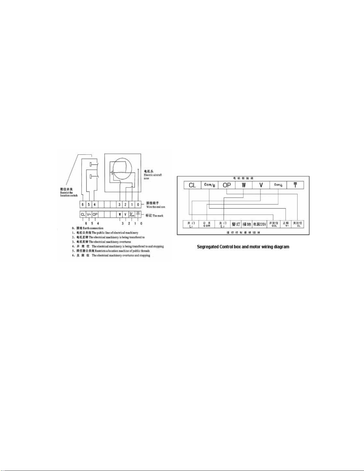
Motor connection:
Motor must installed according to the following diagram,
motor GND line connect to COM on the circuit board, or will cause the problem of
motor single direction operation.
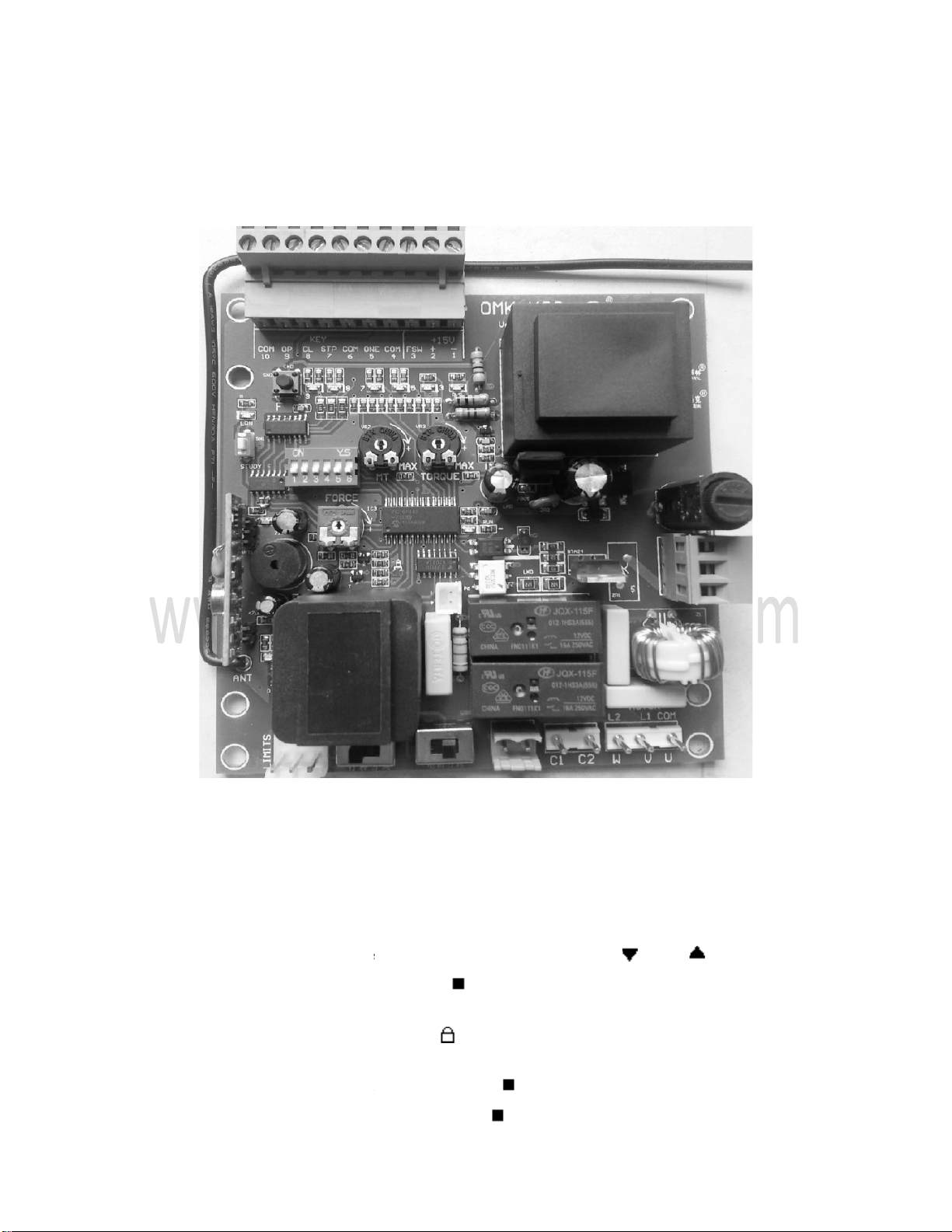
Setting of Red DIP switch on control boa
DIP 1 switch : Single key circulation function
Turn on DIP1 switch to OFF,
Turn on DIP1 to ON=single key circulation,
perform circulation action
.For example:
press open
again=door stop,
again=door open, circulat
e in this way.
DIP 2 switch : OFF
For push switch ( com & one)
DIP 3 switch :
Auto close function
Travel can choose machinery or dry reed board travel.
, direction wires connect to
C.L and O.L.
Motor must installed according to the following diagram,
motor GND line connect to COM on the circuit board, or will cause the problem of
motor single direction operation.
Setting of Red DIP switch on control boa
rd:
DIP 1 switch : Single key circulation function
open close stop
keys control individually.
Turn on DIP1 to ON=single key circulation,
that is with which key to study,
this key will
.For example:
use open to study ,press open
= door open,
again=door stop,
press open once more=door close,
press
e in this way.
Use single key control function.
For push switch ( com & one)
Auto close function
motor GND line connect to COM on the circuit board, or will cause the problem of
keys control individually.
this key will
= door open,
press
open

15
Turn on DIP 3 switch to OFF, without auto close function.
Turn on DIP 3 switch to ON with auto close function.
Auto close time setting: Turn on DIP3 switch and DIP6 switch to ON,
Each press of F key the auto close time delay one second, when reach the demand time,
return DIP6 back to OFF. Auto time setting is completely. When setting auto close
function, the door open to the limit, and perform auto close delay, at the same time function
light flash in 1HZ.
When reach the setting time, the door will auto close.
DIP 4 switch: Soft start and stop function
Turn on DIP 4 to OFF, without soft star and stop function.
Turn on DIP 4 to on, with soft star and stop function.
DIP 5 switch : Maximum starting torque function
Turn on DIP 5 to OFF, the motor starting by MT force
Turn on DIP 5 to ON, the motor starting by full output torque
DIP 6 switch : Set
Turn on DIP6 switch to ON to set the function of circuit board, and return it back to OFF
when the setting is completely.
Auto close function setting:
Users can set the auto close function as their need: stir DIP[3] to ON, auto close function
Working, shut down when connect to OFF. When the auto close function working, the
door travel to limit and execute auto close timing with indicator light flash at 1 Hz. When
reach the Setting time, the controller execute auto close operation.
Soft start and soft stop function setting:
Noted that the soft start and soft stop function can only be set after installation of open and
close limits→power off→ Turn on DIP 4 switch and DIP 6 switch to ON→ power on→
press F key two seconds→ motor start and the door open completely→auto close→ close
completely→ Return DIP 6 switch back to OFF→setting completely.
Note: DIP 6 switch must be return back to OFF after setting.
Otherwise F key as single open function will be invalid.
Function adjustments: increase by clockwise, decrease by anticlockwise
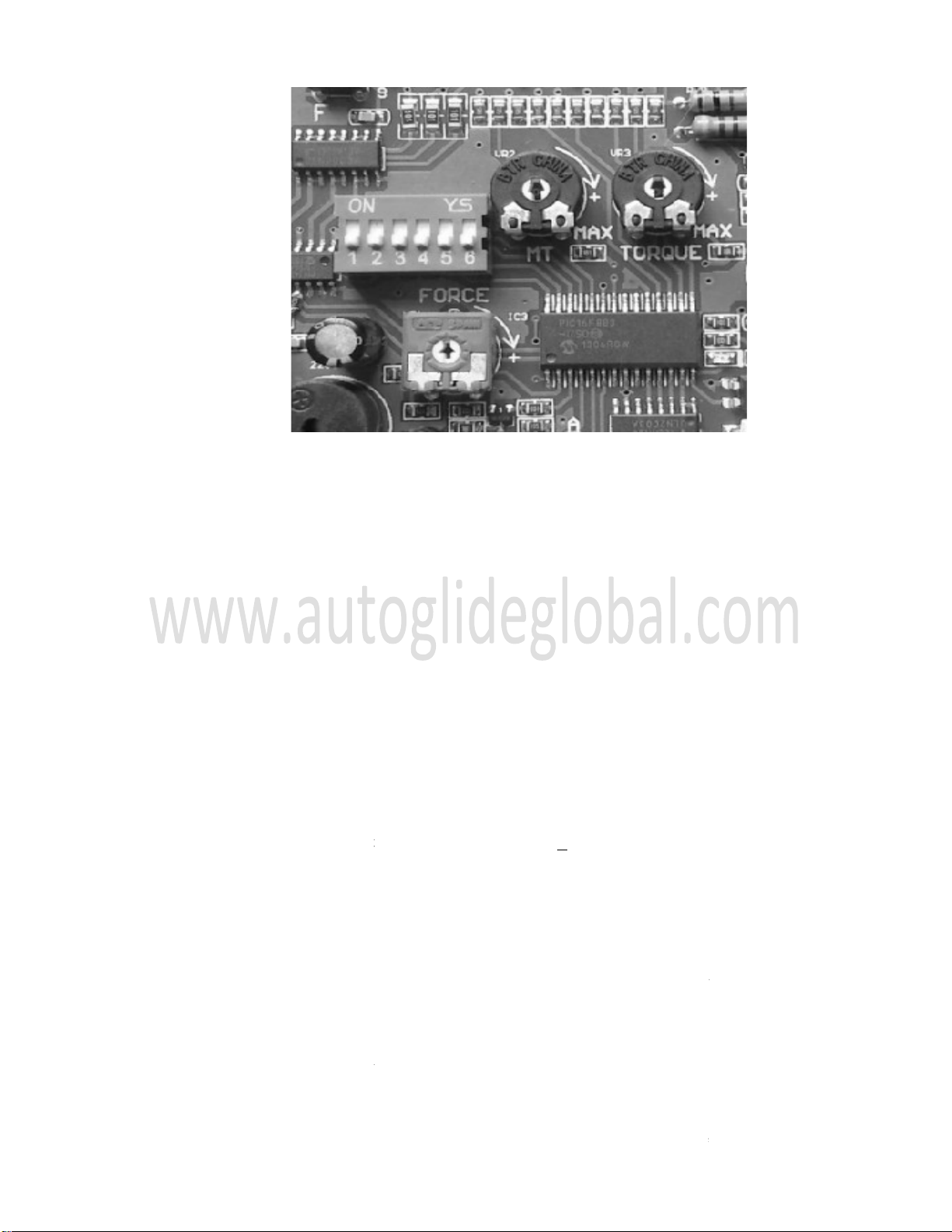
FORCE:
adjust
the strength of resistance when meet obstructions during closing or
opening.
MT:
adjust the starting strength during soft star
TORQUE:
adjust the travel torque of motor:
can be adjust to avoid clamping when the door run into resistance. (Note: at
this time motor is still working, just its force is not strong enough to push the
door, so you must stop the motor working manually
power-
off ),to avo
Attentions:
1. The working voltage of the control box is
2. The wire buried underground should use thick, double conductor. The three
shielding layer of trave
l switch should be well grounded and not a adapter between. The
conducting wire should be set into PVC tube or pipe and do waterproof processing.
3.The default value is 90 seconds. Use battery of DC12V, 27A for remote controller,
working life is one year.
Remote controller can not be moisture, crashed. If want to reset
password, please refer to password setting.
4. If can only control a short distance, please check if the mainframe is installed in the
position
that is shielded by metal objects or nearby.
5. Non-
professional personal is forbidden to install the control box and circuit. We are
out of responsibility
for any personal safeties caused.
6. If the control box has any qu
the strength of resistance when meet obstructions during closing or
adjust the starting strength during soft star
.
adjust the travel torque of motor:
During operating of motor,
the travel
can be adjust to avoid clamping when the door run into resistance. (Note: at
this time motor is still working, just its force is not strong enough to push the
door, so you must stop the motor working manually
(by remote control or
off ),to avo
id long-
time running of the motor and causes problems.
1. The working voltage of the control box is
~220V+ 10%, don’
t connect to 380V.
2. The wire buried underground should use thick, double conductor. The three
l switch should be well grounded and not a adapter between. The
conducting wire should be set into PVC tube or pipe and do waterproof processing.
3.The default value is 90 seconds. Use battery of DC12V, 27A for remote controller,
Remote controller can not be moisture, crashed. If want to reset
password, please refer to password setting.
4. If can only control a short distance, please check if the mainframe is installed in the
that is shielded by metal objects or nearby.
professional personal is forbidden to install the control box and circuit. We are
for any personal safeties caused.
6. If the control box has any qu
ality problem, please send to ag
ent for dealing with. If
the strength of resistance when meet obstructions during closing or
the travel
torque
can be adjust to avoid clamping when the door run into resistance. (Note: at
this time motor is still working, just its force is not strong enough to push the
(by remote control or
time running of the motor and causes problems.
t connect to 380V.
2. The wire buried underground should use thick, double conductor. The three
-core
l switch should be well grounded and not a adapter between. The
conducting wire should be set into PVC tube or pipe and do waterproof processing.
3.The default value is 90 seconds. Use battery of DC12V, 27A for remote controller,
Remote controller can not be moisture, crashed. If want to reset
4. If can only control a short distance, please check if the mainframe is installed in the
professional personal is forbidden to install the control box and circuit. We are
ent for dealing with. If

17
repaired by self, we are out of responsibility for any loss caused by self-repair.
Simply faults and debug:
Ⅰ. When control box has no effective to motor, distinguish is the control box or wire fault.
Judging method: through the indicator lights in the control box to judge the position of
fault. The common faults:
1. Wire broken or unwell connection can check by multimeter.
2. Moisture and electricity leakage, can change wire.
Ⅱ. The fuse of control box burned after connecting to power, check if the voltage is high or
Connect to 380V mistakenly.
Ⅲ. When remote controller is out of order, try to redeploy a new one or check if the remote
Controller has electricity.
Ⅳ. Remote control distance is short:
1. Control in open space >30 meters: since radio wave is affected by weather, the control
Distance will be shorter under bad weather like rainy, foggy, windy. This is normal.
2. Old battery will also make the control distance shorter. Try after replace a new battery.
www.autoglideglobal.com
Table of contents
Other Autoglide Gate Opener manuals


Popular Gate Opener manuals by other brands

Tormatic
Tormatic Digicode 433 Premium Fitting and operating instructions

Chamberlain
Chamberlain ELITE Series Wiring diagram

DITEC
DITEC SECTOR RESET Installation, use and maintenance manual

fadini
fadini HINDI 880 SPRINT instruction manual

DKS
DKS 9200 owner's manual

Viking Access Systems
Viking Access Systems Q-7 installation instructions


 user manual")
