FAAC FAACTOTUM User manual

FA ACTOTUM
FA ACTOTUM
R


INTRODUCTION
FAACTOTUMisan innovativeconceptinthe gateautomation
sectorand providesthepossibilityofcustomisingoperationof
theelectroniccontrolunittomeeteachcustomer’sneedsand
thecharacteristicsofthesystem.
1. DESCRIPTION
Beforegoingontodescribe theuseof theFAACTOTUM,afew
basicpointsshouldbemadeclear:
1.1 What is the FAACTOTUM ?
The FAACTOTUM is a patented portable programmer for the
FAACmodel460P electroniccontrolunit.
Itconsistsof an ABSplastichousing containinganelectronic
cardwithexternallyaccessibleconnectorsforconnectiontothe
460Pcard,toaPCandtoanexternalpowerpack.
The back-lit LCD display allows 4 rows of 20 characters to be
viewed.
Thedisplay lightgoes outafter theFAACTOTUMhasremained
inactiveforone minuteandcomes backonwhen anykeyis
pressed.
Thealphanumerickeyboardisofthepolycarbonatemembrane
type.
Aninternalbuzzer sounds asconfirmationwhen thekeysare
pressed.
Thebatteries fit ina compartmentlocatedin thebackof the
housing.
1.3 How is it used?
The FAACTOTUM can be used to customise operation of the
460Pcard.
To do this it is necessary to set the programming functions
followingthe guidedmenu that appearssequentiallyon the
display.
Totransfer the programto the 460P theFAACTOTUMmust be
connected to the card using the cable provided.
The program is loaded into the nonvolatile memory of the
460P, where it can be subsequently modified, again using
the FAACTOTUM.
Theprogram canalso be savedinthe FAACTOTUM’sinternal
memory (up to 16 programs can be saved) by assigning it
an 8-character alphanumeric name.
It can subsequently be reused on the same system or on
different systems or it can be modified.
Besides programming, the FAACTOTUM can be used to
perform diagnostics and to check the operation of the
automation and the connection to an external PC
(appropriate software provided).
2. FITTINGTHE BATTERIES
The programmer can be powered by 4 non-rechargeable
alkaline batteries of type LR6 AA 1.5V .
Toopenthe battery compartment,useascrewdriveror coin
to undo the screw that fastens the cover onto the back of
the FAACTOTUM,as shown in Fig.2.
Make sure that the batteries are inserted correctly with the
polarities aligned inside the compartment as shown.Close
the cover by doing up the screw.
Whenthe FAACTOTUM isoperatingexclusivelywithbatteries,
it turns itself off automatically after 11 minutes of inactivity
(i.e.no key has been pressed) to save battery charge.
When the programmer comes back on,it displays the last
configuration menu present before it automatically turned
itself off and the previous parameter settings are not lost.
1.2 How is it powered?
The FAACTOTUM has three different electrical power supply
options:
1) When it is connected to the 460P card by the cable,it is
the card itself that supplies power to the FAACTOTUM.
Although in this case the batteries are not actually needed,
it is nonetheless preferable to insert them because they act
asa buffersupply intheeventof a powerfailureandprevent
loss of the configuration currently being set.
2) By battery (4 alkaline LR6AA type inserted in the internal
compartment), which ensure stand-alone operation (i.e.
without being connected to the 460P card).
3) By connection to an external power pack whose
characteristics are given in chapter 3 .
The power pack must not be used when the FAACTOTUM is
connected to the electronic control unit.
Fig.2
1
keypad
display
connectorfor
connectionto460P connectorfor
connectiontoPC connectorfor
externalpowerpack
batterycompartment
Fig.1

2.1 INSTRUCTIONS FOR USING BATTERIES
The batteries last for about twenty hours of continuous
operation.
For correct use of the batteries observe the following
instructions:
-Do not use old and new batteries or different types of
batteries at the same time.
-The batteries must be changed when the FAACTOTUM
display indicates that the charge is running out.
-The batteries must not be exposed to excessive heat or to
naked flames and they must be handled with care.
-If the FAACTOTUM remains inactive for long periods of time,
it is advisable to take the batteries out and to keep them in
a suitable place.
-If acid leaks from the batteries, remove them and clean
the inside of the compartment thoroughly before inserting
new ones.
-Do not use rechargeable batteries.
-Do not attempt to recharge alkaline batteries.
-Dispose of used batteries by placing them in the special
containers for differentiated waste collection.
3. CONNECTION TOAN EXTERNAL POWER PACK
The FAACTOTUM (Fig. 3) has a socket for connection to an
external power pack (not provided).
○ ○ ○ ○○○○○
Theexternalpowerpackconnectorissuitablefortheuseofmost
commercially available power packs.
It is however important to check that the power pack
characteristics and the plug polarity meet the requirements
of table 1.
The external power pack allows the FAACTOTUM to be used
whenitisnotconnectedtotheelectroniccontrolunit460P.
TheFAACTOTUMcanbeconnectedtothepowerpackwiththe
batteries fitted since the external power source is used
preferentiallytosavebatterycharge.
The internal batteries operate as a buffer supply, cutting in if
the power pack fails.
DonotusethepowerpackwhentheFAACTOTUMisconnected
totheelectroniccontrolunit.
Thisconnection isrequiredwheneveritis necessarytotransfer
a program onto the card,to change the program already
presentortoperformdiagnosticsandcheckthefunctionality
of the automation.
Fit oneof the twomale connectors (itdoesn’t matter which)
located at the end of the cable onto the FAACTOTUM
connector (Fig. 4) and the other onto the connector on the
460P card or on the expansion modules,if any are installed
(Fig.5).
Theconnectorsare specially-shapedtoensure thatthey are
inserted the right way round.
When the FAACTOTUM is connected to the card and the
card is powered,it is the card that supplies the programmer
with the electrical current required for operation.
In this case, if the batteries are present the power supply
from the card is used preferentially to save battery charge.
4. CONNECTIONTO 460P
Theconnection betweentheFAACTOTUMand the460P card
is made using the 20-wire flat cable provided.
Fig.4
Fig.5
Fig.3
Warning: when disconnecting the cable from the control
unit or the FAACTOTUM, do not pull the cable directly but
instead hold onto the connector.
2
Table 1 External power pack characteristics
output voltage 12 Vdc
current 100 mA
connector type for dc Ø 2.1 mm
connector polarity positive inside

5. DESCRIPTION OF THE KEYS
The functions of the FAACTOTUM keys are follows:
1
6
2
7
3
8
4
9
5
0
CLEAR
ENTER
A
K
U
C
M
W
E
O
Y
G
Q
I
S
ON-OFF
PG
PG
ESC
?
TOTUM
F1 F2 F3 F4 F5
*/-+
.
SHIFT
BD FH J
LN PR T
VX Z
1
2
2
3
4
5
6
6
4
7
8
9
Fig. 6
4
ARROW RIGHT/LEFT
Press the arrow keys to move sideways in a menu to select
the desired option.
Once selected,press ENTER to confirm.
5
CLEAR
CLEAR
Thiskey cancelsthedata item whichhasbeen entered and
is shown on the display but has not yet been confirmed by
pressing the ENTER key.
6
1
6
F1
*
A C
BD
ALPHANUMERIC KEYS
Thealphanumerickeys areused for
entering data into the data entry
fields in the menus and to activate
the functions F1...F5
(the only function key currently enabled is F1=space).
Each key is divided into two parts: one part has a white
background, the other a grey background. The normal
function of the key is shown by the character on the white
background.
When pressed together with the SHIFT key (see point 8) the
key has the function shown by the character on the grey
background.
9
?
HELP
When enabled,this key providesuseful information regarding
programming.
8
SHIFT
SHIFT
Press this key to activate the alternative function of keys
which have a double function (e.g.alphanumeric keys).
Press and hold before pressing the key with the double
function.
7
ESC
ESC
Press this key to return to the initial menu for the subject for
which programming is being performed.
3
3
ENTER
ENTER
Press this key to confirm the selected option or data item
and make it active,and to go to the subsequent menu.
Before pressing ENTER the data item is shown on the display
but is not saved in the memory. So if for example you return
to the previous menu the data item will be lost.
1
ON-OFF
ON/OFF
Press this key to turn the FAACTOTUM on and off.
Warning: if the programmer is turned off before the
configuration currently being set has been saved in the
memoryorithasbeentransferredto the460P cardmemory,
all the program data entered will be lost.
2
PG
PG
ARROW UP/DOWN
PAGE UP/PAGE DOWN
Press the arrow keys to move up and down within
amenu toselect thedesiredoption.Presstogether
with the SHIFT key (see point 8) to move back-
ward or forward by several menus (where ena-
bled).
Theyare alsousedin the time learningandmotor
test cycle.

6. USING THE FAACTOTUM
The FAACTOTUM allows easy access to functions grouped
under three different main menus:
- Programming
- Diagnostics
- Special functions
The Programming mode is used to set the 460P card char-
acteristics and operating parameters.
It is important to distinguish between program and operat-
ing logic.
The logic consists of a series of indications (electronic regis-
ters) which instruct the 460P card (the microprocessor) on
how to behave according to the state of the gate and the
state of the terminal block inputs.
The conventional logics (LogicsA,S,E,EP, P,B,C and B/C) are
already available on the FAACTOTUM and it is also possible
to create new customised logics usingAdvanced Program-
ming.
A program includes the logic and other parameters which
specify the characteristics of the automation.
Card programming is performed according to a guided se-
quence of menus which appear in turn on the FAACTOTUM
display.
Generallyeachmenu requires aresponseor apieceof data
to be entered before proceeding to the subsequent menu.
In many of the menus the permitted choices are shown to
simplify programming.
Each selectable choice is associated with a number and
an arrow-shaped cursor indicates the currently active se-
lection.
see PROGRAMMING paragraph
see DIAGNOSTICS paragraph
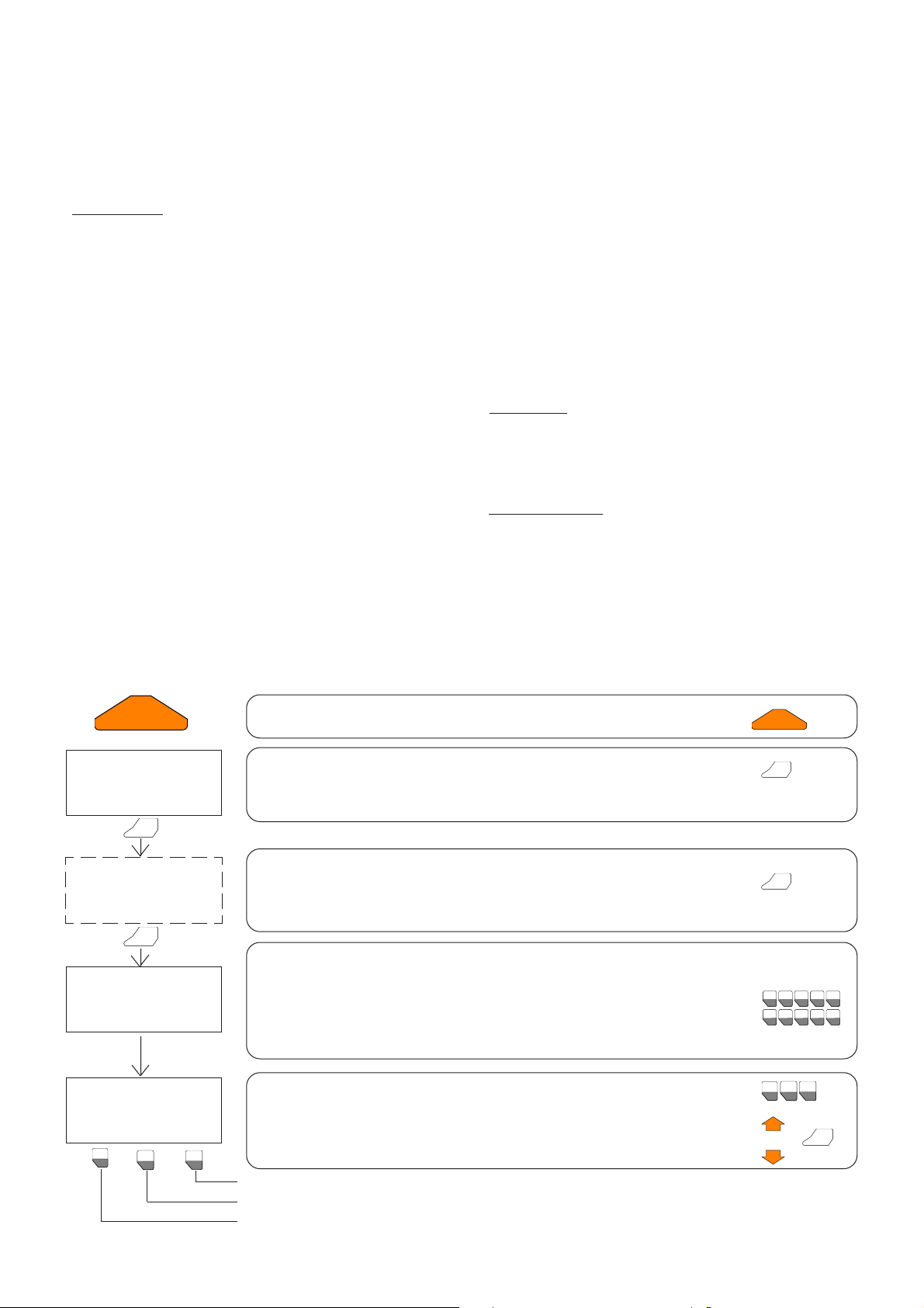
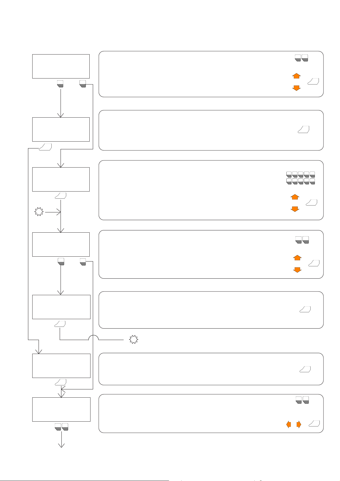
Pressthe ON button.
The initial screen shows the FAACTOTUM version number.
PressENTERtocontinue.Otherwiseafter5secondstheprogramautomatically
proceedstothenextmenu.
This message appears when the battery charge is running out: replace the
batteries.
Press the ENTER key to ignore this message and proceed.
If the password protection function has been enabled, enter the correct nu-
merical code. If you enter the incorrect password, an error message appears
asking you to press ENTER to return to this menu.
➲This function prevents the FAACTOTUM from being used by anyone who does
notknow the password,butit does not preventaccess totheconfigurationsaved
onthe 460P card.
Select the mode by moving the arrow-shaped cursor alongside the desired op-
tion using the vertical movement keys and pressing ENTER,or key in directly the
number for the desired function.
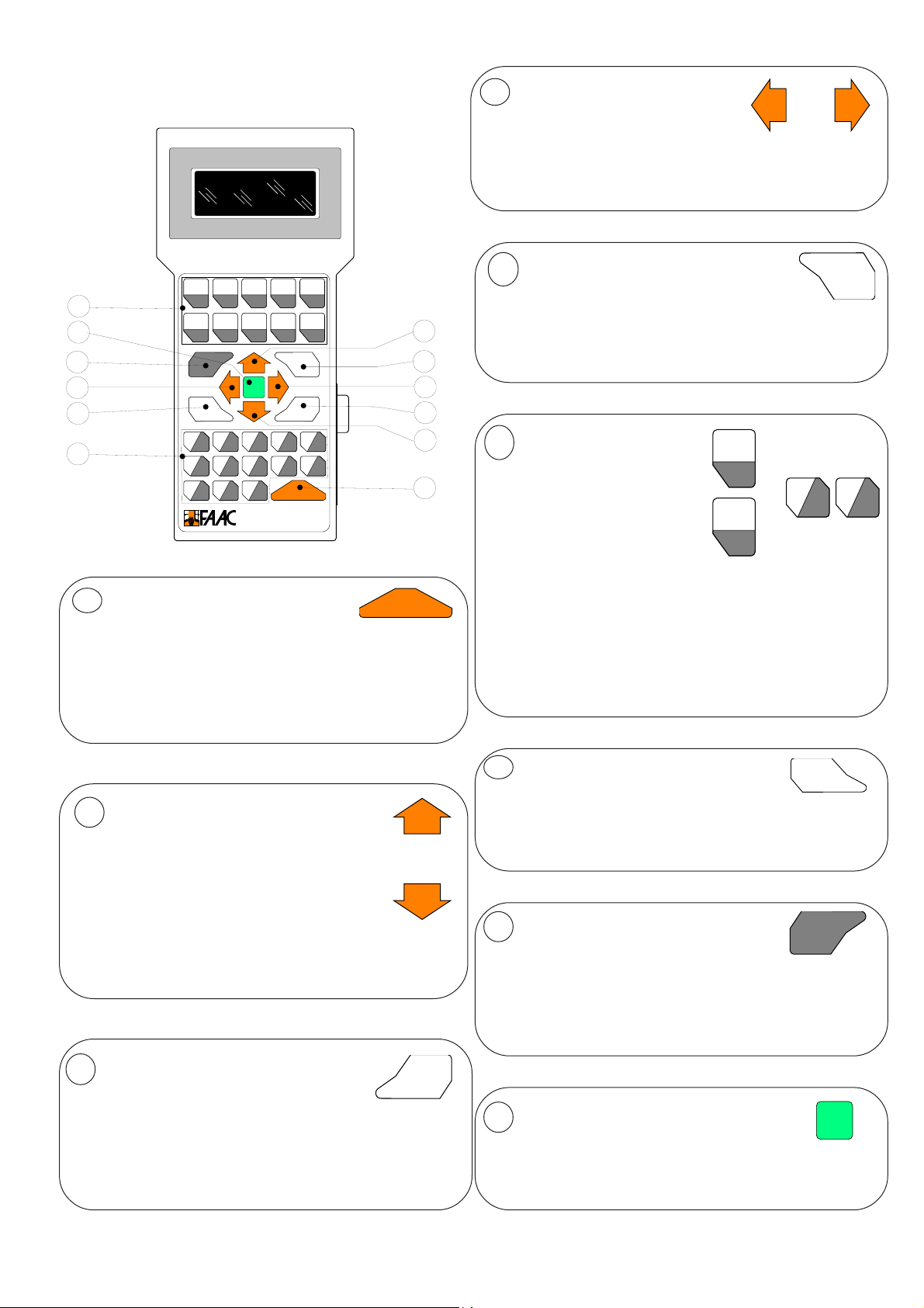
ENTER
ENTER
ON-OFF
PG
PG
ENTER
+
1
F1
3
F3
2
F2
or
1
6
2
7
3
8
4
9
5
0
F1 F2 F3 F4 F5
*/-+
.
REPLACE BATTERIES
ON-OFF
FAACTOTUM V1.0
- - - - - - - - - - - - - - - - - - -
FAAC S.p.A.
BOLOGNA - ITALY
INSERT
PASSWORD
*****
ENTER
ENTER
see SPECIAL FUNCTIONS paragraph
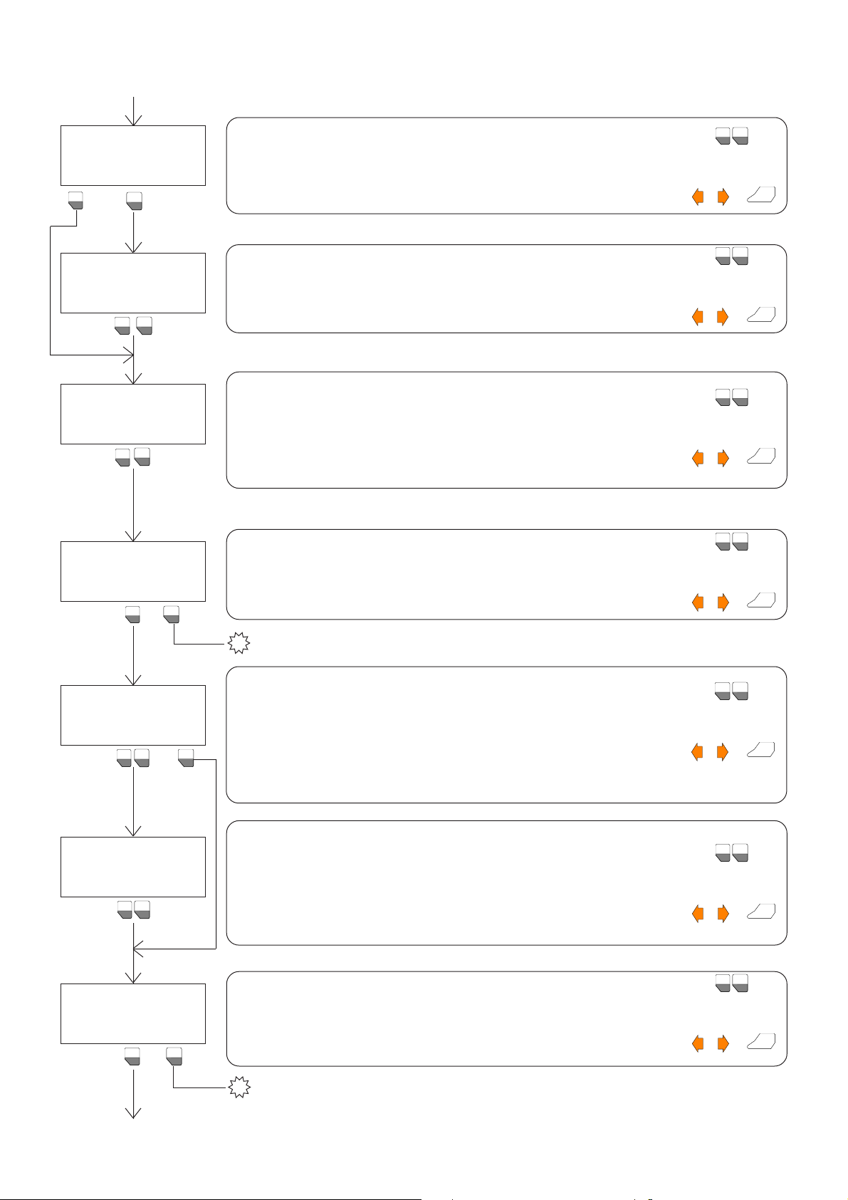
7. MODE SELECTION
There are two ways of changing the selection:
1) move the cursor to the desired choice using the vertical
or horizontal arrow keys (2-4,fig.6) and press ENTER (3,fig.6)
to confirm and go to the next menu.
2)enterthenumber corresponding to thedesired selection.
In the menus requiring a numerical or alphanumeric value
to be entered,after entering it press ENTER to confirm and
go to the subsequent menu.
During the programming phase the choices made with
menus can alter the sequence of the subsequent menus
becausetheones which areunnecessary will automatically
be skipped.
It is not advisable to turn off or disconnect the FAACTOTUM
during the programming sequence.
Until programming has been completed and the program
saved on the card and/or in the FAACTOTUM memory,turn-
ing the FAACTOTUM off will result in the loss of entered data
and it will therefore be necessary to restart programming
from scratch.
The Diagnostics mode can be used to check the voltages
on the card,the state of the terminal block inputs and the
state of the gate.
Also available is a motor test and completed cycle count
function (total and partial).
The Special functions mode comprises menus for language
selection,forpasswordsetting,forresettingthe standard con-
figuration of the card and for connecting the FAACTOTUM
to the PC.
SELECT MODE:
1->PROGRAMMING
2 DIAGNOSTICS
3 SPECIAL FUNCTIONS
4
MENU DESCRIPTION KEYS USED
1
F1
3
F3
2
F2
à
à
à

Select the source from which you wish to load the program:
1 = From 460P if you wish to work on the program already present on the card
2 = From the memory if you wish to work on a program previously saved in the
FAACTOTUM memory
Make the choice by moving the arrow-shaped cursor alongside the desired
option using the òand ñkeys and pressing ENTER,or key in the corresponding
number directly.
1
F1
2
F2
or
PG
PG
ENTER
+
8. PROGRAMMING
LOAD
PROGRAM
1->FROM 460P
2 FROM MEMORY
2
F2
1
F1
CONNECT TO 460 P
AND PRESS ENTER
SELECT MEMORY WITH
ñAND ò
THEN PRESS ENTER
MEMORY : 1 xxxxxxxx
ENTER
ENTER
DO YOU WANT TO
1-> CHANGE
2 TRANSFER
1
F1
2
F2
ENTER
CONNECT TO 460 P
AND PRESS ENTER
ENTER
PROGRAMMING
XXXXXXXX
PRESS ENTER TO CONT.
1
F1
2
F2
NUMBEROF OPERATORS?
1->ONE 2 TWO
Ago to
“8.7 TRANSFERRING THE PROGRAM TO THE CARD”
à
E
(cont.)
To load the program from the 460P, the FAACTOTUM must be connected to it
using the appropriate cable.
- If the FAACTOTUM is already connected,press ENTER
- If the FAACTOTUM is disconnected,connect it and press ENTER
If you press ENTER with the FAACTOTUM disconnected, an error message ap-
pears.
In this case press ENTER to return to this menu.
ENTER
To load the program from the FAACTOTUM’s internal memory,it must be selected
from those available.
Each program in the memory is represented by a number (01 to 16 indicating its
memory location) and an 8-character alphanumeric identification.If you know
thenumber,enterit(thecorresponding identificationwillappear) and pressENTER.
Alternatively,pressing the òand ñkeys displays all the memory locations one at
a time along with the resident program identifications.To select the desired pro-
gram,press ENTER when its identification is shown.
or
1
6
2
7
3
8
4
9
5
0
F1 F2 F3 F4 F5
*/-+
.
PG
PG
ENTER
+
Once the program resident in the FAACTOTUM memory has been selected,it is
possible to:
1 = Modify it then save in memory
2 = Transfer it directly to the 460P
Make the selection by moving the arrow-shaped cursor alongside the desired
option using the and òkeys and pressing ENTER,or directly enter the number
corresponding to the desired function.
ò
1
F1
2
F2
or
PG
PG
ENTER
+
To transfer the program to the 460P the FAACTOTUM must be connected to it using
the appropriate cable.
- If the FAACTOTUM is already connected, press ENTER.
- If the FAACTOTUM is disconnected,connect it and press ENTER.
The subsequent menus allow the program to be transferred.
If you press ENTER with the FAACTOTUM disconnected,an error message appears.
ENTER
ENTER
The identification of the program loaded from the 460P is displayed.
If appears,this means that the 460P standard configuration has
been loaded.
Press ENTER to proceed.
òòòòòòò
5
Number of operators present in the automation:
1 = Single leaf (1 operator)
2 = Double leaf (2 operators)
Make the selection by moving the arrow-shaped cursor alongside the desired
option using the ïand ðkeys and pressing ENTER, or key in the corresponding
number directly.
1
F1
2
F2
or
ENTER
+
ò

USE GATECODER ?
1 YES 2 ->NO
2
F2
1
F1
USE LIMIT SWITCHES?
1->YES 2 NO
SLOW DOWN LEAVES?
1->YES 2 NO
1
F1
2
F2
ELECTRIC LOCK?
1 YES 2->NO
CLOSING?
1-> ONE 2 TWO 3 NO
1
F1
3
F3
8.1 ELECTRIC LOCKS
2
F2
REVERSING STROKE?
1-> YES 2 NO
1
F1
2
F2
1
F1
2
F2
OPENING ELECTRIC LOCK?
1-> YES 2 NO
go to
“8.2 LOGIC SELECTION”
B
à
1
F1
2
F2
1
F1
2
F2
6
(cont.)
(cont.)
Useof limitswitchesonautomation:
1 = Limit switches used
2= Limit switchesnotused
1
F1
2
F2
or
ENTER
+
Makethe selectionbymovingthe arrow-shapedcursoralongsidethedesired option
using the ïand ðkeys and pressing ENTER,or key in the corresponding number
directly.
Deceleration is performed by using the GATECODER,using the limit switches or by
time,depending onthechoicesmade. Choosewhethertousethe leafdeceleration
function:
1=Useleafdecelerationfunction
2=Donotuseleafdecelerationfunction
1
F1
2
F2
or
ENTER
+
Makethe selectionbymovingthe arrow-shapedcursoralongsidethedesired option
using the ïand ðkeys and pressing ENTER,or key in the corresponding number
directly.
Select option:
1 = Electric lock(s) used
2 = Electric lock(s) not used - go to logic selection.
1
F1
2
F2
or
ENTER
+
Make the selection by moving the arrow-shaped cursor alongside the desired
option using the ïand ðkeys and pressing ENTER,or key in the corresponding
number directly.
Theinversionstrokecausesashortclosuremovementbeforetheleavesopen to
facilitateoperationoftheclosedpositionelectriclocks.
Selectoption:
1=Inversionstrokeenabled
2= Inversion stroke disabled
1
F1
2
F2
or
ENTER
+
Make the selection by moving the arrow-shaped cursor alongside the desired
option using the ïand ðkeys and pressing ENTER,or key in the corresponding
number directly.
Useof electric locks on thesystemtolockthegatein an open position:
1= Open position electric lockspresent
2= Openpositionelectriclocks notpresent-goto logicselection.
1
F1
2
F2
or
ENTER
+
Make the selection by moving the arrow-shaped cursor alongside the desired
option using the ïand ðkeys and pressing ENTER,or key in the corresponding
number directly.
UsingtheGATECODER on the automation:
1 = Use GATECODER
2 = Do not use GATECODER
Makethe selection bymovingthearrow-shapedcursor alongside thedesiredoption
using the ïand ðkeys and pressing ENTER,or key in the corresponding number
directly.
1
F1
2
F2
or
ENTER
+
Enterthenumberofelectriclocksintheautomationwhichlockthegateinaclosed
position:
1= 1 closedpositionelectriclock(electric lock onleaf1)
2=2 closed position electric locks (electric locks on leaf 1andleaf2)
3= noclosedpositionelectric lock
➲Option 2 appears only if“NUMBER OF OPERATORS = 2”has been set.
1
F1
2
F2
or
ENTER
+
Makethe selectionbymovingthe arrow-shapedcursoralongsidethedesired option
using the ïand ðkeys and pressing ENTER,or key in the corresponding number
directly.
go to
“8.2 LOGIC SELECTION”
B
à

REVERSING STROKE?
1-> YES 2 NO
1
F1
2
F2
8.2 LOGIC SELECTION
B
LOGIC : XXXXXXXX
1-> CURRENT
2 STANDARD
3 CUSTOMISED
SELECT LOGIC WITH
ñAND òAND HIT ENTER
LOGIC: 1 XXXXXXXX
SET PAUSE TIME
T= xxx [0-255 sec]
ENTER
SET LEAF
OPENING DELAY:
T= xxx [0-255 sec]
ENTER
SET LEAF
CLOSURE DELAY:
T= xxx [0-255 sec]
ENTER
ENTER
8.3 ASSIGN INPUTS
(
cont.)
7
(cont.)
The inversion stroke causes a brief opening movement before the leaves close to
facilitate operation of the open position electric locks.
Select option:
1 = Enable inversion stroke
2 = Disable inversion stroke
1
F1
2
F2
or
ENTER
+
Make the selection by moving the arrow-shaped cursor alongside the desired
option using the ïand ðkeys and pressing ENTER,or key in the corresponding
number directly.
This menu displays the currently used logic and provides the option of changing it
by selecting one of the logics contained in the FAACTOTUM memory:
1 = Maintain currently loaded logic
2 = Use preloaded standard logics (A,S,E,EP, P,B,C or B/C)
3 = Use customised logics created with advanced programming
1
F1
3
F3
2
F2
or
PG
PG
ENTER
+
Make the selection by moving the arrow-shaped cursor alongside the desired
option using the ñand òkeys and pressing ENTER,or key in the corresponding
number directly.
Each logic is represented by a number (01 to 16) indicating the memory location
and an alphanumeric identification (max. 8 characters).
To select a different logic,press the ñand òkeys to scroll through the logics avail-
able and their identifications.
When the desired logic appears,press ENTER to select it.
If you know the location,key in the number (the identification appears) and press
ENTER.
or
1
6
2
7
3
8
4
9
5
0
F1 F2 F3 F4 F5
*/-+
.
PG
PG
ENTER
+
➲This menu appears only if an automatic logic has previously been selected.
Enter the pause time in seconds (permitted values in brackets) using the number
keys,then press ENTER.
1
6
2
7
3
8
4
9
5
0
F1 F2 F3 F4 F5
*/-+
.
ENTER
+
➲This menu appears only if“NUMBER OF OPERATORS = 2”has previously been
set.
With a single leaf this time is automatically set to zero.
The opening leaf delay is the time that elapses between opening activation of
motor M1 and that of motor M2 (delayed on opening).
Enter the opening leaf delay time in seconds (permitted values in brackets)
using the number keys,then press ENTER.
When a closed position electric lock is used on each leaf, the set delay must be
longer than the electric lock activation time (standard 1 s).
1
6
2
7
3
8
4
9
5
0
F1 F2 F3 F4 F5
*/-+
.
ENTER
+
➲This menu appears only if“NUMBER OF OPERATORS = 2”has previously been
set.
With single leaf operation this time is automatically set to zero.
The closure leaf delay is the time that elapses between closure activation of
motor M2 and that of motor M1 (delayed on closing).
Enter the closure leaf delay time in seconds (permitted values in brackets)
using the number keys,then press ENTER.
When a closed position electric lock is used on each leaf, the set delay must be
longer than the electric lock activation time (standard 1 s).
1
6
2
7
3
8
4
9
5
0
F1 F2 F3 F4 F5
*/-+
.
ENTER
+
1
F1
2
F2
3
F3

8.4 TIME LEARNING
go to
“8.5 ADVANCEDPROGRAMMING”
8.3 INPUT ASSIGNING
Card 460P and the input expansion module (MEI module) have a default terminal block input alloca-
tion,which is the one given in the electronic control unit instructions.
However,with the exception of input 1 of the 460P (which represents the OPEN-A input and cannot be
changed),a different meaning can be assigned to the other available inputs in accordance with the
rules and limitations given in chapter 12“Input management”in this manual.
Time learning serves to determine the working and deceleration times of each leaf.
As the motors are activated during this phase,it is advisable to check beforehand that the automation
works correctly (by running the “motor test”under the Diagnostics menu) and calibrate the by-pass
valves.
You can quit the learning cycle at any time (with consequent loss of the acquired times) by pressing the
ESC key,which takes you back to the beginning of the cycle.
N.B.:
1) The time learning cycle is displayed only if the FAACTOTUM is connected to the 460P control unit.
2) The“DECELERATE”option in the cycle menus appears only if Gatecoder is used,or if deceleration by
time is used.
3) When the limit switches are used,the“DECELERATE”option does not appear because the decelera-
tion start point is determined by the opening of the limit switch contact.
4) In the case of swing gates, the mechanical opening and closure stops are always necessary for
correct operation of the automation (even when the Gatecoder is used).
5) Leaf 1 is the leaf connected to motor M1; Leaf 2 is the leaf connected to motor M2.
8
ENTER
➲This menu appears only if“NUMBER OF OPERATORS = 2”has previously been set.
When the ñkey is pressed,leaf 2 starts to close; when it is pressed again the leaf
stops closing and so on.
Each time the key is pressed,the arrow on the display moves to select the effect of
the subsequent pulse.
Close Leaf 2 completely and press ENTER.
(cont.)
ASSOCIATE CHOSEN
FUNCTION WITH INPUT
AND PRESS ENTER
INP. 2 = XXXXXX
ENTER
INPUT MODULE?
1->YES 2 NO
1
F1
2
F2
C
à
When the ñkey is pressed,leaf 1 starts to close; when it is pressed again the leaf
stops closing and so on.
Each time the key is pressed,the arrow on the display moves to select the effect
of the subsequent pulse.
Close Leaf 1 completely and press ENTER.
ENTER
(cont.)
TIME LEARNING?
1->YES 2 NO
2
F2
1
F1
ENTER
CLOSE LEAF 1
ñCLOSE
STOP
PRESS ENTERTO CONT.
CLOSE LEAF 2
ñCLOSE
STOP
PRESS ENTERTO CONT.
ENTER
The currently attributed function is shown for each available input (except for
inputs IN1 on the 460P and IN10-11 on the MEI module):
Press ENTER to confirm.
To modify,use ñand òto select the function you wish to assign to the input and
press ENTER.
Pressing the CLEAR key shows the input’s default function.
The input can also be disabled by selecting the“INACT”function.
All the inputs must be set in order to proceed to the subsequent menu.
Whenconfirming each configuredsafetyinput (FSW-OP/CL,SAFE OP/CL),amenu
allows the Failsafe to be enabled or disabled.
➲Do not assign the same function to more than one inputs.
To skip the allocation cycle (and confirm the current settings), hold down the
SHIFT key and press the òkey.
PG
PG
ENTER
CLEAR
SHIFT
Check whether the Input Expansion Module (MEI module) is installed in the 460P
card and select the corresponding option:
1 = MEI module installed
2 = MEI module not installed
Make the selection by moving the arrow-shaped cursor alongside the desired
option using the ïand ðkeys and pressing ENTER,or key in the corresponding
number directly.
1
F1
2
F2
or
ENTER
+
Select option:
1 = Perform time learning cycle
2 = Do not perform time learning cycle and go to“Advanced programming”
1
F1
2
F2
or
ENTER
+
Make the selection by moving the arrow-shaped cursor alongside the desired
option using the ïand ðkeys and pressing ENTER,or key in the corresponding
number directly.

ENTER
ò
CLOSE LEAF 2
CLOSE
STOP
PRESS ENTERTO CONT.
ENTER
CONFIRM CYCLE?
1->YES 2 NO
1
F1
➲This menu appears only if“NUMBER OF OPERATORS = 2”has previously been set.
When the ñkey is pressed,Leaf 2 begins to close; when it is pressed again the
leaf stops closing and so on.
Each time the key is pressed,the arrow on the display moves to select the effect
of the subsequent pulse.
Close Leaf 2 completely and press ENTER.
2
F2
2
F2
CONFIRM CYCLE?
1->YES 2 NO
1
F1
CLOSE LEAF 1
ñCLOSE
STOP
PRESS ENTERTO CONT.
ENTER
OPEN LEAF 2
òOPEN
DECELERATE
STOP
OPEN LEAF 1
òOPEN
DECELERATE
STOP
When the òkey is pressed,Leaf 1 begins to open and the arrow on the display
moves alongside the “DECELERATION”option.
When Leaf 1 has reached the position where you wish opening deceleration to
begin,press the òkey again to save the position.The arrow on the display moves
alongside the“STOP” option.
When Leaf 1 reaches the open position against the mechanical stop,wait for a
few seconds (necessary for correct operation of the automation) then press the
òkey again to end the cycle.
CLOSE LEAF 2
ñCLOSE
DECELERATE
STOP
CONFIRM CYCLE?
1->YES 2 NO
1
F1
2
F2
➲This menu appears only if“NUMBER OF OPERATORS = 2”has previously been set.
When the òkey is pressed,Leaf 2 begins to open; when it is pressed again the
leaf stops opening and so on.
Each time the key is pressed,the arrow on the display moves to select the effect
of the subsequent pulse.
Open leaf 2 completely and press ENTER.
OPEN LEAF 2
òOPEN
STOP
PRESS ENTERTO CONT.
ENTER
ENTER
9
When the ñkey is pressed,Leaf 1 begins to close; when it is pressed again the
leaf stops closing and so on.
Eachtimethekeyispressed,thearrowonthedisplaymovestoselecttheeffectofthe
subsequentpulse.
Close Leaf 1 completely and press ENTER.
ENTER
➲This menu appears only if“NUMBER OF OPERATORS = 2”has previously been set.
When the ñkey is pressed,Leaf 2 begins to close and the arrow on the display
moves alongside the“DECELERATION”option.
When Leaf 2 has reached the position where you wish closing deceleration to
begin,press the ñkey again to save the position.The arrow on the display moves
alongside the “STOP”option.
When Leaf 2 reaches the closed position against the mechanical stop,wait for a
few seconds (necessary for correct operation of the automation) then press the
key again to end the cycle.
(cont.)
(cont.)
Request for confirmation of cycle just completed:
1 = Cycle confirmed
2 = Repeat cycle
Makethe selectionbymovingthe arrow-shapedcursoralongsidethedesired option
using the ïand ðkeys and pressing ENTER,or key in the corresponding number
directly.
1
F1
2
F2
or
ENTER
+
➲This menu appears only if“NUMBER OF OPERATORS = 2”has previously been set.
When the òkey is pressed,Leaf 2 begins to open and the arrow on the display
moves alongside the “DECELERATION” option.
When Leaf 2 has reached the position where you wish opening deceleration to
begin,press the òkey again to save the position.The arrow on the display moves
alongside the“STOP” option.
When Leaf 2 reaches the open position against the mechanical stop,wait for a
few seconds (necessary for correct operation of the automation) then press the
òkey again to end the cycle.
➲This menu appears only if“NUMBER OF OPERATORS = 2”has previously been set.
Request for confirmation of cycle just completed:
1 = Cycle confirmed
2 = Repeat cycle
1
F1
2
F2
or
ENTER
+
Make the selection by moving the arrow-shaped cursor alongside the desired
option using the ïand ðkeys and pressing ENTER,or key in the corresponding
number directly.
ò

1
F1
2
F2
CLOSE LEAF 1
ñCLOSE
DECELERATE
STOP
go to
“8.6 SAVING IN PROGRAMMING MEMORY”
C
8.5 ADVANCEDPROGRAMMING
Advanced programming allows you to modify some special parameters which are not frequently used.
This type of programming does not follow a guided menu, but directly sets the values of the internal
registers of the microprocessor.
Since incorrectly changing some registers could result in incorrect operation of the automation, it is
advisable to use advanced programming with caution and only after carefully reading chapter 13
“Setting registers”.It is also advisable to modify one parameter at a time and to verify the effect this has
on the operation of the automation.
Select the register for the parameter to be set.
Enter the register number using the number keys.
Press ENTER to confirm and proceed.
Press ESC to return to the previous menu.
1
6
2
7
3
8
4
9
5
0
F1 F2 F3 F4 F5
*/-+
.
ENTER
+
or
ESC
!!
10
When the ñkey is pressed, Leaf 1 begins to close and the arrow on the display
moves alongside the“DECELERATION”option.
When Leaf 1 has reached the position where you wish closing deceleration to
begin,press the ñkey again to save the position.The arrow on the display moves
alongside the “STOP”option.
When Leaf 1 reaches the closed position against the mechanical stop,wait for a
few seconds (necessary for correct operation of the automation) then press the
ñkey again to end the cycle.
When the òkey is pressed, Leaf 1 begins to open; when it is pressed again the
leaf stops opening and so on.
Each time the key is pressed,the arrow on the display moves to select the effect
of the subsequent pulse.
Open leaf 1 completely and press ENTER.
ENTER
(cont.)
(cont.)
OTHER REGISTER?
1 YES 2->NO
Using the òand ñkeys, move the arrow-shaped cursor alongside the most suit-
able options for entering the register value:
DEC = to enter the register value in decimal
BIN = to enter the register value in binary
If DEC is selected,enter the value using the number keys.
If BIN is selected, press the ðkey to select the bit that requires changing and
enter the value (0 or 1).
Changing the decimal value at the same time changes the binary value and
viceversa.
Press the CLEAR key to reset the register value.
Press ENTER to continue.
1
6
2
7
3
8
4
9
5
0
F1 F2 F3 F4 F5
*/-+
.
ENTER
PG
PG
CLEAR
MODIFY THE REG.XX
-> DEC=XXX
BIN =XXXXXXXX
PRESS ENTER TO CONT.
ENTER
CHANGE REGISTER
N.XX
PRESS ENTER TO CONT.
ESC TO EXIT
ENTER
ATTENTION!!!
BEFORE TO PROCEED
CONSULT
INSTRUCTIONS
ENTER
CONFIRM CYCLE?
1->YES 2 NO
1
F1
OPEN LEAF 1
òOPEN
STOP
PRESS ENTERTO CONT.
ENTER
2
F2
D
ADVANCEDPROGRAMMING?
1 YES 2->NO
2
F2
1
F1
Flashing message warning the user to exercise particular care when setting the
registers after entering advanced programming.
In particular, make changes only to the registers for which an explanation is given
in the instructions.
Press ENTER to proceed, otherwise after about 7 seconds the FAACTOTUM will
return automatically to the previous menu.
ENTER
Request for confirmation of cycle just completed:
1 = Cycle confirmed
2 = Repeat cycle
Make the selection by moving the arrow-shaped cursor alongside the desired
option using the ïand ðkeys and pressing ENTER,or key in the corresponding
number directly.
1
F1
2
F2
or
ENTER
+
Select option:
1 = Enter advanced programming
2 = Skip advanced programming and go to “Saving in programming memory”.
1
F1
2
F2
or
ENTER
+
Make the selection by moving the arrow-shaped cursor alongside the desired
option using the ïand ðkeys and pressing ENTER,or key in the corresponding
number directly.
Select option:
1 = Other register to change
2 = No other register to change
Make the selection by moving the arrow-shaped cursor alongside the desired
option using the ïand ðkeys and pressing ENTER,or key in the corresponding
number directly.
1
F1
2
F2
or
ENTER
+

SAVE NEW LOGIC?
1 YES 2->NO
D
8.6 SAVING IN PROGRAMMING MEMORY
1
F1
2
F2
1
F1
2
F2
SELECT LOGIC
(ñAND ò) ENTER NAME
AND PRESS ENTER
LOGIC: 1 XXXXXXXX
ENTER
SELECT MEMORY
(ñAND ò) ENTER NAME
AND PRESS ENTER
MEMORY: 1 XXXXXXXX
ENTER
Use the ñand òkeys to select the memory location in which you wish to save
the new customised logic.
If you already know the location,enter the number directly.
If the location is occupied,the name of the resident logic appears.
Once you have decided on the location,press ðand enter the alphanumeric
identification (max. 8 characters). Pressing CLEAR cancels the characters
contained in the field.
After entering the identification,press ENTER to save and proceed.
If you select an occupied location, saving will cause the resident logic to be
overwritten.
A
K
U
C
M
W
E
O
Y
G
Q
I
S
BD FH J
LN PR T
VX Z
1
6
2
7
3
8
4
9
5
0
F1 F2 F3 F4 F5
*/-+
.
ENTER
PG
PG
CLEAR
DOWNLOAD PROGRAM?
1->YES 2 NO
1
F1
2
F2
Use the ñand òkeys to select the memory location in which you wish to save
the program.
If you already know the location,enter the number directly.
If the location is occupied,the name of the resident program appears.
Once you have decided on the location,press ðand enter the alphanumeric
identification (max. 8 characters). Pressing CLEAR cancels the characters
contained in the field.
After entering the identification,press ENTER to save and proceed.
If you select an occupied location,saving will cause the resident configuration to
be overwritten.
A
K
U
C
M
W
E
O
Y
G
Q
I
S
BD FH J
LN PR T
VX Z
1
6
2
7
3
8
4
9
5
0
F1 F2 F3 F4 F5
*/-+
.
ENTER
PG
PG
CLEAR
SAVE IN MEMORY?
1 YES 2->NO
11
A
8.7 TRANSFERRING THE PROGRAM TO THE CARD
SELECT MODE
(cont.)
If registers used by the logic have been changed,the customised logic can be
saved in the FAACTOTUM internal memory.
Select option:
1 = Save the new logic in the memory
2 = Do not save the new logic in the memory
Make the selection by moving the arrow-shaped cursor alongside the desired
option using the ïand ðkeys and pressing ENTER,or key in the corresponding
number directly.
1
F1
2
F2
or
ENTER
+
It is now possible to save the program in the FAACTOTUM internal memory for
future use.
Select option:
1 = Save program in FAACTOTUM memory
2 = Do not save program
Make the selection by moving the arrow-shaped cursor alongside the desired
option using the ïand ðkeys and pressing ENTER,or key in the corresponding
number directly.
1
F1
2
F2
or
ENTER
+
➲This menu appears only if the FAACTOTUM is connected to the 460P card.
Select option:
1 = Transfer the program to the 460P electronic control unit
2 = Do not transfer the program to the 460P electronic control unit
Make the selection by moving the arrow-shaped cursor alongside the desired
option using the ïand ðkeys and pressing ENTER,or key in the corresponding
number directly.
1
F1
2
F2
or
ENTER
+

The states of all inputs on the 460P card terminal block (inputs 1-5) and on the MEI
module if present (inputs 6-11) are displayed in real time.
By activating the activation device connected to each input it is possible to
verify operation by noting the change in status of the symbol alongside:
= Contact open = Contact closed
N.B.:
1) The inputs are numbered according to the physical layout of the terminal
block without taking account of the meaning assigned to them.The correctness
of the state of the input must be determined according to the function assigned
to the terminal.
2) When the Gatecoder is used,the respective input shows a sequence of con-
tact open/closed states when the gate is moving.
Press ENTER to proceed.
ENTER
9. DIAGNOSTICS
ENTER
CONNECT TO 460P
AND PRESS ENTER
CHECK VOLTAGES
Vbat +Vrl +5V Vacc
^^^^
OK OK OK OK
ENTER
12
The FAACTOTUM checks the following voltages:
Vbat = FAACTOTUM internal battery voltage
Vrl = 460P card relay power supply voltage (12Vdc)
+5V = 460P card logic power supply voltage (5Vdc)
Vacc = Accessories power supply voltage (24Vdc)
The message OK appears next to each correct voltage.
If this message does not appear for one or more voltages, this means that the
measured voltage is lower than it should be or is absent.
For further information, read chapter 11“Checking voltages”.
ENTER
To perform complete diagnostics on the automation, the FAACTOTUM must be
connected to the 460P electronic control unit.
Press ENTER to continue.
ENTER
The menus contained in the diagnostics (with the exception of the voltage check menu) are shown
only if the FAACTOTUM is connected to the card.
Thesemenusprovidevaluable assistance forchecking the functionality of the system and fordiagnostics,
and also provide information on the degree of usage of the automation.
SOFTWARE VERSION
460P
X.X
The 460P card software version is shown.
Press ENTER to continue.
ENTER
During installation,before performing the time learning cycle,it is advisable to check that the
automation is working correctly by performing the motor check.
The by-pass valves should also be regulated by following the specific instructions for the hydraulic
operator.
➲
INPUT STATES
1 2 3 4 5
6 7 8 9 10 11
ENTER
The following information is displayed in real time:
1) STATE = State of the automation
The envisaged states are:
-CLOSED = Gate closed
-PREFL.OPEN = Opening pre-flashing
-OPENING = Gate opening
-OPEN TMP = Timed opening (operation of closure safety edge)
-OPEN = Gate open
-PAUSE = Gate on pause
-PREFL.CLOS = Closure pre-flashing
-CLOSING = Gate closing
-CLOS.TMP = Timed closure (operation of opening safety edge)
-STOP OPEN = Stops then opens
-STOP CLOS. = Stops then closes
-STOP FSW-C = Closure safety tripped
-STOP FSW-O = Opening safety tripped
-PANIC = Panic opening device control activated
-PROGRAMM. = Programming
ENTER
GATE STATE
STATE CLOSED
LAMP OFF
OUT F.TX ON RX OK
ENTER
ENTER
(cont.) (cont.)

IMPULSE COMMAND
MOTOR 1
òOPEN ñCLOSE
CLEAR STOP ENT CONT.
Motor M1 operation test:
ò= Start motor M1 for opening
= Start motor M1 for closure
CLEAR = Stop movement
ENTER = Stop movement and go to subsequent menu
ò
ENTER
PG
PG
CLEAR
ESC
1
F1
2
F2
ENTER
ENTER
IMPULSE COMMAND
MOTOR 2
òOPEN ñCLOSE
CLEAR STOP ENT CONT.
13
2) LAMP = State of warning lamp
The possible states are:
- ON =Warning light on
- OFF = Warning light off
3) OUT F.TX = State of photocell projector power supply
The possible states are:
- ON = Supply to projectors on
- OFF = Supply to projectors off
If the Failsafe is not enabled, the normal state is ON. Only when the photocell
check is performed (Failsafe enabled) does the state momentarily become OFF.
4) RX = Result of FAILSAFE check
The possible states are:
- OK = The Failsafe has run correctly
- KO = The Failsafe has found a fault
With the FAACTOTUM connected to the card, it is possible to check the state of
the automation according to the operation of the various activation devices
under this menu.
Press ENTER to continue.
➲ This menu appears only if“NUMBER OF OPERATORS = 2”has been set.
Motor M2 operation test:
ò= Start motor M2 for opening
= Start motor M2 for closure
CLEAR = Stop the movement
ENTER = Stop movement and go to next menu
ò
ENTER
PG
PG
CLEAR
ESC
CYCLES COUNTER
TOTAL
XXXXXXXX
CYCLES COUNTER
PARTIAL
XXXXXXXX
CLEAR RESET
ENTER
ENTER
IMPULSE COMMAND
1 OPEN-A 2 OPEN-B
3 STOP 4 CLOSE
ESC TO EXIT
From the time of its installation,the 460P counts the number of cycles performed
by the automation to give an idea of its degree of usage.
A cycle is counted upon each opening movement.
The total number of cycles (which cannot be reset) is shown in this menu.
Press ENTER to continue.
Display of number of cycles performed since last reset.
Press the CLEAR key to reset the counter.
Press ENTER to continue.
➲ The number of partial cycles is contained inside the configuration program
and is overwritten every time a program (saved in the FAACTOTUM internal
memory) is transferred to the card.
The control pulses are sent using the following number keys:
1=OPEN-A 2=OPEN-B 3=STOP 4=CLOSE
➲Whereas the control pulses sent by external activation devices reach the
microprocessor via special electronic components called optoisolators,those
sent via the FAACTOTUM reach the microprocessor directly.
This means that it is possible not only to test the automation without the need
to operate on the external activation devices,but also to test the efficiency of
the optoisolators.
Press ENTER to continue.
TEST MOTOR?
1->YES 2 NO
ENTER
SELECT MODE
(cont.)
(cont.)
ENTER
ENTER
ENTER
ESC
CLEAR
1
F1
2
F2
3
F3
4
F4
Select option:
1 = Perform motor operation test
2 = Do not perform motor operation test
1
F1
2
F2
or
ENTER
+
Make the selection by moving the arrow-shaped cursor alongside the desired
option using the ïand ðkeys and pressing ENTER,or key in the corresponding
number directly.

10. SPECIAL FUNCTIONS
SELECT LANGUAGE WITH
ñAND òAND HIT ENTER
ENGLISH
Menuforselecting the language to be used in the FAACTOTUMdisplaymessages.
Use the arrow keys and òto select the desired language and press ENTER.
The selected language will be active the next time the FAACTOTUM is turned
on.
ò
PG
PG
ENTER
+
ENTER
This menu shows the currently set password.
Use the number keys to enter the new FAACTOTUM password (5 characters).
PresstheCLEARbuttonifyou wish to disable the password protection function.
➲If you forget the password which has been set it will be impossible to use the
FAACTOTUM. In this case contact FAAC S.P.A.
1
6
2
7
3
8
4
9
5
0
F1 F2 F3 F4 F5
*/-+
.
ENTER
PG
PG
CLEAR
ENTER
PC CONNECTION
ENTER
LOAD BASIC CONFIGU.?
1->YES 2 NO
The FAACTOTUM memory contains a copy of the standard configuration of the
460P card.
If it is necessary to reset the initial configuration on the card, it can be loaded
from this menu.
Select option:
1 = Load 460P standard configuration resident in the FAACTOTUM
2 = Ignore the question and proceed
1
F1
2
F2
SELECT MODE
14
1
F1
2
F2
or
ENTER
+
Make the selection by moving the arrow-shaped cursor alongside the desired
option using the ïand ðkeys and pressing ENTER,or key in the corresponding
number directly.
TheFAACTOTUMis readyto transferthe contents of itsmemory whenrequestedby
theconnectedcomputer.
Specialsoftware mustbeinstalledonthecomputer.Theconnectionmustbemadeusing
the special cable between the computer serial port (COM1 or COM2) and the
FAACTOTUM serial connector (see fig.1).
Bytransferringtheprogramsandlogicstoandfromthecomputeritispossibletocreate
arationalandusefulconfigurationsarchive.
Oncetheconnectionhasbeenmade,allthestepsrequiredfortransferareperformed
bytheprograminitiatedonthecomputer(refertotherelevantinstructions).
PressENTER tointerrupttheconnection andreturntotheinitial modeselectionmenu.
ENTER
CHANGE
PASSWORD
XXXXX
Ego to“PROGRAMMING”
à

12. INPUT MANAGEMENT
The 460P can control the following inputs:
➲Leaf 1 is the leaf connected to motor M1
Leaf 2 is the leaf connected to motor M2
Fig.7
IN1 IN2 IN3 IN4 IN5
OPEN-A
OPEN-B
STOP
FSW-CL
FSW-OP
J2
460P
12.2 460P WITH MEI MODULE
The 5 inputs on the 460P card plus the 6 inputs on the MEI
module available by default are shown in Fig. 8
IN1 IN2 IN3 IN4 IN5
OPEN-A
OPEN-B
STOP
FSW-CL
FSW-OP
J2
460P
IN6 IN7 IN8 IN9 IN10
CLOSE
J1
MEI
IN11
Fig. 8
SAFE-CL
SAFE-OP
EMERG
GC1/FCA1
GC2/FCC1
12.1 460P WITHOUT MEI MODULE
The 5 inputs on the 460P card available by default are
shown in Fig.7
15
➲ Limitations in assigning of inputs:
1)TerminalIN1(OPEN-A)doesnotappearintheassigningcycle
becauseitcannotbechanged.
2)TerminalsIN2-IN5canbeassigneddifferentfunctionstothose
set by default, chosen among inputs 6-13 given in table 2.
3) Limit switches cannot be used at the same time as the
Gatecoderandviceversa.
4)Withthesoleexceptiongivenbelow,itisnotpossibletoassign
thesamefunctiontomorethanoneterminal.
5) The 460P card terminal IN2 can also be configured as a
secondOPEN-A inputso thatif anopening activationdevice
short-circuitson oneofthe twoinputs,the activationdevices
connected to the other input continue to control the
automationasnormal.
6) It is not possible to move an input which already has an
assigneddefaultterminalonthe460Pcard(e.g.theSTOPfunction
cannotbeassignedtoterminalIN5onthe460Pcard).
7) Each terminal, with the exception of IN1 and IN2, can be
disabled by selecting the “INACT” function in the input
assigning cycle.
Inputs IN6-IN9 are active without the need for programming
using the FAACTOTUM,simply by inserting the MEI module in
the 460P with standard configuration.
➲ Limitations in assigning of inputs:
1)TheterminalIN1(OPEN-A)doesnotappearintheassigning
cycle because it cannot be changed.
2) Terminals IN10-IN11 do not appear in the assigning cycle
because they are setdirectly by the FAACTOTUM according
to the selections made during programming (use of
Gatecoder or limit switches). If neither the Gatecoder nor
the limit switches are used they are inactive.
3) If the limit switches are used, terminals IN2-IN9 can be
assigned different functions to those set by default,chosen
among inputs 12-13 given in table 2.
4) Limit switches cannot be used at the same time as the
Gatecoder and vice versa.
5) With the sole exception given below,it is not possible to
assign the same function to more than one terminal.
6) The 460P card terminal IN2 can also be configured as a
secondOPEN-A inputsothatifan openingactivationdevice
short-circuitsonone ofthetwoinputs,theactivation devices
connected to the other input continue to control the
automation as normal.
7) It is not possible to move an input which already has an
assigned default terminal on the terminal block of the 460P
card or the MEI module (e.g.the stop function cannot be
assigned to terminal IN5 on the 460P card).
8) Each terminal, with the exception of IN1, IN2, IN10 and
IN11, can be disabled by selecting the “INACT” function in
the input assigning cycle.
11. VOLTAGE CHECK
The voltages on the 460P card tested by the FAACTOTUM are
protected from short-circuit by fuses:
Fuse F1 = transformer primary
Fuse F2 = accessories power supply (24Vdc)
Fuse F3 = relay (12Vdc) and logic (5Vdc) power supply
Furthermore,an electronicprotection systempreventsfuse F3
from burning out in the event of a short on the 5Vdc circuits.
The following are a few suggestions if any of the voltages are
found to be absent in the FAACTOTUM test:
1) If Vrl and +5V are absent, check fuse F3 and replace if
burned out.
If the voltages do not return,take out the accessory modules
and replace the fuse to check that one of them is not the
cause.
If the problem persists,try replacing the control unit.
2) If the +5V voltages are absent,try removing the MEI mod-
ule (if present).
If the problem continues,try replacing the control unit.
3) If the Vacc voltage is absent, check the fuse F2 and re-
place it if burned out.
Ifthevoltagedoesnot return,removethe accessorymodules
andallthe accessories connectedtothe card andtry again.
If the fuse no longer burns out,connect the previously discon-
nected accessories and modules one at a time until the fuse
burns out again,thereby identifying the cause.
Table 2
No. Input Description Type
1 OPEN-A total leaf opening N.O.
2 OPEN-B single leaf opening N.O.
3 STOP stops movement N.C.
4 FSW-CL closure safety photocells N.C.
5 FSW-OP opening safety photocells N.C.
6 CLOSE closure command N.O.
7 SAFE-CL closure safety edge N.C.
8 SAFE-OP opening safety edge N.C.
9 EMERG panic device N.C.
10/a GC1 Gatecoder leaf 1 signal
11/a GC2 Gatecoder leaf 2 signal
10/b FCA1 leaf 1 opening limit switch N.C.
11/b FCC1 leaf 1 closing limit switch N.C.
12 FCA2 leaf 2 opening limit switch N.C.
13 FCC2 leaf 2 closing limit switch N.C.

Table 3 Systemconfigurationregisters
16
13. SETTING REGISTERS
The registers are the electronic “containers” in which the
characteristicsandinformationrequiredfor operation ofthe
automation are written. The registers are identified by a
number and consist of 8 bits each.
Each bit has a specific meaning and its setting (possible
values 0 and 1) modifies the behaviour of the automation.
Every time a programming cycle is performed, the
FAACTOTUM automatically sets the registers according to
the selections that have been made in the various menus.
However,by enteringAdvanced Programming,it is possible
to modify the settings of the registers directly.
Someregistersare devoted todefiningthe effectofthepulse
according to the gate state.These are the so-called“Logic
registers”.By modifying these registers it is possible to create
customised operating logics and save them in the
FAACTOTUM memory. The other “System configuration
registers” contain parameters which determine operation
of the automation regardless of the type of logic.
To modify a register, refer to its number to select it and
identify the bit to be set by following the tables given: the
meanings of the 0 and 1 settings are given for each bit.
A valueexpressed inseconds mustbe entered inthe registers
containing times.
REGISTER NO. VALUE MEANING DEFAULT
1 0XXXXXXX 50Hzmainspowersupply
50 Hz
1XXXXXXX 60Hzmainspowersupply
30
XXXXXXX0 FAILSAFEoninputFSW-CLdisabled
disabled
XXXXXXX1 FAILSAFEoninputFSW-CLenabled
XXXXXX0X FAILSAFEoninputFSW-OPdisabled
disabled
XXXXXX1X FAILSAFEoninputFSW-OPenabled
XXXXX0XX FAILSAFEoninputSAFE-CLdisabled
disabled
XXXXX1XX FAILSAFEoninputSAFE-CLenabled
XXXX0XXX FAILSAFEoninputSAFE-OPdisabled
disabled
XXXX1XXX FAILSAFEoninputSAFE-OPenabled
32
SECONDS LEAF1openingtime
25
33
SECONDS LEAF1openingdecelerationtime 0
34
SECONDS LEAF1closuretime
25
35
SECONDS LEAF1closuredecelerationtime 0
36
SECONDS LEAF2openingtime
25
37
SECONDS LEAF2openingdecelerationtime 0
38
SECONDS LEAF2closuretime
25
39
SECONDS LEAF2closuredecelerationtime 0
40 SECONDS LEAF2openingdelay 2
41
SECONDS LEAF1closuredelay 5
42
SECONDS Pausetime
25
44
SECONDS Reducedpausetime(delayonclosurecommandwhilegateisonpause) 5
45
SECONDS Opening1pre-flashingtime 0
46
SECONDS Closure1pre-flashingtime 0
47
SECONDS Opening2pre-flashingtime(seesafetylogicregisters) 0
48
SECONDS Closure2pre-flashingtime(seesafetylogicregisters) 0
49
SECONDS Timedopeningtime(uponactivationofsafetyedgeand/orGatecoderanti-crushingsafety) 2
50
SECONDS Timedclosuretime(uponactivationofsafetyedgeand/orGatecoderanti-crushingsafety) 2
51
SECONDS Finalopeningtimeatfullspeed(openingover-pushingstroke) 0
52
SECONDS Finalclosuretimeatfullspeed(closureover-pushingstroke) 0
53
SECONDS Obstaclerecognitiontime(atfullspeed) 1
54
SECONDS Stoprecognitiontime(duringdeceleration) 4
55
SECONDS Reversingstrokeduration 1
56
SECONDS Electriclockactivationtime(mustalwaysbelessthanleafopening/closingdelay) 1

14.1 PRE-FLASHING
Pre-flashingis afunction which,with theautomation stopped
andtheflashinglightoff,allowstheflashinglighttocome ona
fewsecondsbeforemovementbegins.Programmabletypesof
pre-flashing:
1) Opening pre-flashing 1
Theflashinglight ispowered for theset time beforeswitching
fromtheclosed/lockedstatetotheopeningstate.
2) Closure pre-flashing 1
Theflashinglight ispowered for theset time beforeswitching
fromtheopen/openonpause/stoppedstatetotheclosurestate.
3) Pre-flashing at end of pause
Theflashinglight ispowered for theset time atthe end ofthe
pausebeforestartingthemovement.
14.2 FLASHING LIGHT ON DURING PAUSE
Theflashinglightispoweredfortheentiredurationofthepause.
REG. No.
VALUE FUNCTION DEFAULT
45 seconds openingpre-flashingtime 0
REG. No.
VALUE FUNCTION DEFAULT
14 * XXXXXX1X pre-flashingatendofpause XXXXXX0X
REG. No.
VALUE FUNCTION DEFAULT
14 * XXXXX1XX flashing lightonduringpause XXXXX0XX
14.3 WARNING LIGHT ON DURING CLOSURE
Setsthe warninglightto stayoneven duringclosure: theonly
stateinwhichitisoffisautomationclosed.
Default:openingpre-flashingdisabled(0seconds)
Default:closingpre-flashingdisabled(0seconds)
Default:pre-flashingatendofpausedisabled
Default:flashinglightoffduringpause
14.4 WARNING LIGHT OUTPUT OPERATION
Allowsthe460Pwarninglightoutput(N.O.contact)tobeusedfor
otherfunctions:
1)Timed courtesy light contact
ThewarninglightoutputN.O.contactclosesforasettabletime
(Reg.79)duringeachopening,closure,photocelloperationand
pausestartoftheautomation.
Everystatewhichcausesthecontacttocloseresetsandrestarts
thetimingcount.
REG. No.
VALUE FUNCTION DEFAULT
14 * 0100XXXX warninglightonduringclosure 0000XXXX
Default:standardoperationofthewarninglampis:
automation closed = warning light off
automation closing = warning light flashing
all other states = warning light on
2) Panic state active contact
Thewarning lightoutput N.O.contactcloseswhenthe panic
stateisactivatedintheelectroniccontrolunit460Pfollowingthe
“EMERG”command.
The contact remains closed until the state is reset.
REG. No.
VALUE FUNCTION DEFAULT
14 * 1001XXXX panicstateactivated 0000XXXX
Default:standardwarninglightfunction
3) Automation open state contact
ThewarninglightoutputN.O.contactclosesfortheentiretime
theautomationremainsintheopenortheopenonpausestates.
REG. No.
VALUE FUNCTION DEFAULT
14 * 1010XXXX automationopen/pausestate 0000XXXX
Default:standardwarninglightfunction
4)Automation opening state contact
ThewarninglightoutputN.O.contactclosesfortheentiretime
theautomationremainsintheopeningstate.
REG. No.
VALUE FUNCTION DEFAULT
14 * 1011XXXX automationopeningstate 0000XXXX
Default:standardwarninglightfunction
5) Automation closure state contact
ThewarninglightoutputN.O.contactclosesfortheentiretime
theautomationremainsintheclosurestate.
REG. No.
VALUE FUNCTION DEFAULT
14 * 1100XXXX automationclosurestate 0000XXXX
Default:standardwarninglightfunction
6) Stop impulse active contact
ThewarninglightoutputN.O.contactclosesfortheentiretime
thestopbutton ispressed.
REG. No.
VALUE FUNCTION DEFAULT
14 * 1101XXXX stopbuttonpressed 0000XXXX
Default:standardwarninglightfunction
7) Automation pause state contact
ThewarninglightoutputN.O.contactclosesfortheentiretime
theautomationremainsinthepausestate.
REG. No.
VALUE FUNCTION DEFAULT
14 * 1110XXXX automationinpausestate 0000XXXX
Default:standardwarninglightfunction
8) Automation closed state contact
ThewarninglightoutputN.O.contactclosesfortheentiretime
theautomationremainsintheclosedstate.
REG. No.
VALUE FUNCTION DEFAULT
14 * 1111XXXX automationclosedstate 0000XXXX
Default:standardwarninglightfunction
REG. No.
VALUE FUNCTION DEFAULT
46 seconds closurepre-flashingtime 0
14. EXAMPLES OF REGISTER SETTINGS
Thefollowingaresomeexamplesofregistersettingsforthemost
usefulfunctions,completewithexplanations.
➲Theregistersmarkedwith anasterisk(*) are“Logicregisters”
(seechapter13).
REG. No.
VALUE FUNCTION DEFAULT
79 seconds contactclosuretime 100
Default: 100 seconds
17
REG. No.
VALUE FUNCTION DEFAULT
14 * 1000XXXX timedcourtesycontact 0000XXXX
Default:standardwarninglightfunction
REG. No.
VALUE FUNCTION DEFAULT
48 seconds pre-flashingtimeat end ofpause 0
Default: 0 seconds

14.6 TIMED CLOSURE TIME
Sets the reversal to timed closure following activation of the
Gatecoderanti-crushingsafetyor the“SAFE-OP”safety.
REG. No.
VALUE FUNCTION DEFAULT
50 seconds timed closure time 2
Default:2seconds
14.7 OPENING OVER-PUSHING STROKE
Setsthefinal openingtimeatfullspeed.
Whenthemotorscompletetheiropeningcycle,theyareactivated
againforopeningatfullspeedforthesettime.
REG. No.
VALUE FUNCTION DEFAULT
51 seconds opening over-pushing stroke 0
Default:openingover-pushingstrokedisabled(0sec.)
14.8 CLOSURE OVER-PUSHING STROKE
Setsthefinalclosingtimeatfull speed.
Whenthemotorscompletetheirclosurecycle,theyareactivated
againforclosureatfullspeedforthesettime.
REG. No.
VALUE FUNCTION DEFAULT
52 seconds closure over-pushing stroke 0
Default:closureover-pushing strokedisabled(0sec.)
14.9 OBSTACLE RECOGNITION TIME
Theanti-crushingsafetyisobtained using theGatecoder, by
way of electronic speed control performed by the 460P.
Anobstacleisdetectedwhenitimpedesthenormalmovement
oftheautomation.
Theintervaloftimebetweentheobstacleimpedingmovement
and the activation of timed reversal of movement or
stopping can be programmed:
REG. No.
VALUE FUNCTION DEFAULT
53 seconds obstaclerecognition(full speed) 1
Default:1second
1) Obstacle recognition time at full speed
Thisisthe time settoactivate the anti-crushingsafety(timed
reversal)inthepresenceofanobstacleduringmovementatfull
speed(notduringdeceleration).
2) End stop recognition time during deceleration
This is the time set to stop the motors in the presence of an
obstacleduringdeceleration.Itisalsothetimeusedforrecogni-
tionofthemechanicalendstopduringdecleration.
Default: 4 seconds
14.11 ELECTRIC LOCK ACTIVATION TIME
Sets the duration of electric lock activation.
➲Thesetvaluemustbelowerthantheopeningandclosingleaf
delaytimes.
REG. No.
VALUE FUNCTION DEFAULT
56 seconds electric lock activation time
Default:1second
REG. No.
VALUE FUNCTION DEFAULT
54 seconds obstaclerecognition(deceleration) 4
14.12 TIMER FUNCTION
The 460P electronic control unit can be programmed for
access control via an external timer.
Use automatic logics (A or S) only.
Operating notes:
1)Closure of timer contact
The leaf or leaves open and remain open until the timer
contact reopens.
2)Opening of timer contact
Theleafor leaves closeandare setupfor normal operation.
3) If the power supply fails during the opening time period
controlledby thetimer,when powerreturnsthe 460P powers
the motors to open, thereby returning the leaf or leaves to
theopencondition.
4)Ifthe timer actsonthe singleleaf,givingthetotal opening
command(OPEN-A) whilethesingle leafis openalsocauses
the other leaf to open.
Make the connection as shown in Fig.9, choosing whether
the timer is to act on total opening (OPEN-A) or partial
opening(OPEN-B)oftheleavesandsetthefollowingregisters.
1
REG. No.
VALUE FUNCTION DEFAULT
5 * XX1XXXXX timerfunction
Default:timerfunction disabled
6 * XXXXX1X1 timer function
14.10 REVERSING STROKE DURATION
Setstheduration oftheopening/closing reversingstroke.The
reversing stroke, which facilitates operation of the electric
locks,is performed if set in the FAACTOTUM programming.
REG. No.
VALUE FUNCTION DEFAULT
55 seconds duration of reversing stroke 1
Default:1second
18
14.5 TIMED OPENING TIME
Thissetsthetimedopeningreversaltimefollowingactivationof
theGatecoderanti-crushingsafetyorthe“SAFE-CL”safety.
REG. No.
VALUE FUNCTION DEFAULT
49 seconds timed opening time 2
Default: 2 seconds
TIMER
IN1 IN2 6
OPEN-A
OPEN-B
-
460P
Fig. 9
XX0XXXXX
XXXXX0X0
Table of contents
Other FAAC Gate Opener manuals

FAAC
FAAC E391 User manual

FAAC
FAAC D700HS User manual

FAAC
FAAC 413 Series User manual

FAAC
FAAC 422 Standard User manual

FAAC
FAAC 770 COMPACT User manual

FAAC
FAAC 750 Standard User manual

FAAC
FAAC Safe Zone S418 User manual

FAAC
FAAC 746 ER CAT User manual

FAAC
FAAC 550 User manual

FAAC
FAAC Safe Zone S418 User manual
Popular Gate Opener manuals by other brands

Nice Apollo
Nice Apollo HYPPOETL installation manual

Atecnica
Atecnica B320 INSTRUCTIONS AND RECOMMENDATIONS FOR THE INSTALLER

Avidsen
Avidsen 114461 manual

AES
AES i-GATE 20 installation manual

Manaras Opera
Manaras Opera Opera-GH Installation and instruction manual

GFA
GFA 10003831 10012 installation instructions