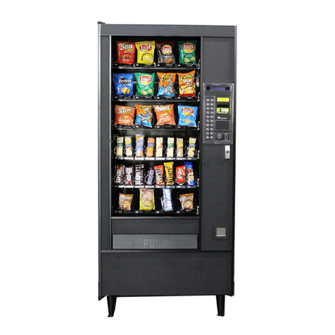
unpacking
_
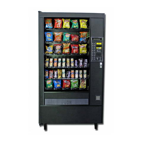
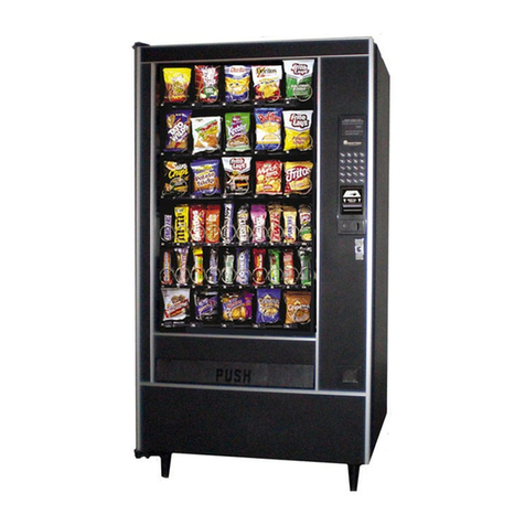
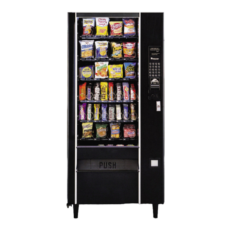
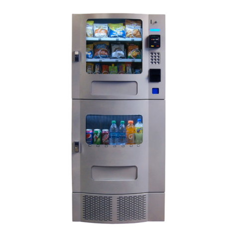
The Snackshop 7000
is
assembled and packed
so
that
amini-
mum
amount
of
time
is
necessary
for
preparation to install
it
on location. The
following
steps
are
recommended to insure
correct unpacking.
1. Shipping Damage:
Thoroughly
inspect the
exterior
of
the
carton
for
damage which may
have
occurred during ship-
ment. Report any damage
to
delivering carrier and
follow
their
instructions.
2.
Remove staples
from
lower
edge
and those at top
of
car-
ton,
and slit carton vertically
at
the taped corner. Open
and remove carton. Remove-the remainder
of
the packing
material. On machines shipped
with
lock
in
place, the
keys
are
stapled to the carton
base.
3. Remove Vendor With A
Fork
Lift
Truck:
Remove the car-
ton
from
the vendor. Open the
door
on the vendor and
remove the hold down bracket at the
front
center
of
the
cabinet
base
and
close the vendor door. From the
front
of
the vendor
tip
the vendor backward and run forks under
the cabinet.
4. Removing Vendor
Without
A
Fork
Lift
Truck:
Remove
the carton
from
the vendor. Remove
v..
"piece
of
plywood
installation
1.
GENERAL:
In
some
locations, due
to
the
size
of
this
machine
it
is
not
possible
to
move the
fully
assembled
machine through doors
or
narrow hallways. For
such
locations the door
of
this vendor
can
be
removed, thus
reducing the clearance required down to
32
inches. For
narrower doors the sliding panel
can
be
pushed back in·
side the cabinet by removing the control stop (Item
#23
Page
24).
DOOR REMOVAL:
To
remove the door, swing door
to
90
degrees. Remove bolt and washer on door end
of
door
stop.
Disconnect light harness. The upper hinge
is
secured to the
cabinet
by
one bolt extending through the hinge from the
in-
side
of
the cabinet. Use a1/2 socket to remove. Pull the door
forward, the upper hinge will slide out of the top guide, free-
ing the door. Lift the door up and out of the lower hinge.
Remove left side panel extension which
is
held byfour screws.
Remove the cabinet to door filler assembly which
is
held
in
by
twelve
screws.
To
install the door, reverse the
above
procedure.
2.
LEVELING
THE
MACHINE
on location
is
important
for
the proper
function
of
the machine. The
four
leveling
screws in the
legs
are
the means
of
leveling the machine.
After
positioning the machine, level machine in
front
to
rear
and
right to
left
directions.
After
leveling, turn
front
right (lock side) leveling screw in about one-half
turn
to
drop this corner slightly to make the
door
easier
to
close
and lock.
3.
THE
MAIN
POWER CORD
is
shipped
fully
inside the
machine. Extend
it
through the hole located in the
base
on the
left
(hinge side)
of
the machine behind the trans-
former. Install the plate
with
key hole slots over the
two
screws in the
base
by the cord hole
and
drive screws
tight
to hold cord in place. Plug the 3pin grounded plug
into
a
properly grounded
115V
60
HZ
outlet
only.
In order to comply
with
electrical safety regulations
and
Underwriters Laboratories requirements, all electrical
4
located just
beh
ind the
front
legs,
then open the door on
the vendor
and
remove the hold down bracket at the
front
center
of
the cabinet
base
and close vendor door. From
the
front
of
the vendor
tip
the vendor back far enough
to
clear the wood strip across the
front
of
the
base.
Slide
vendor toward the back
until
the back
legs
are
off
the
base
and
pull
base
out.
NOTE:
Because
the weight concentration is toward the
back
of
the cabinet,
trucking
and
lifting
should be done
from
the back.
CAUTION
should
be
taken when
trucking
from
side.
5.
On machines
with
lock in place, unlock,
and
turn
handle
to
open door.
When
no lock
is
furnished, remove tape
and
turn handle. Swing door
to
its full open position.
6.
Remove all packing tape
and
paper
from
various
areas
of
machine
and
the shipping strap.
7.
Warranty: The warranty card
is
attached
to
the cover
of
this manual.
It
must
be
filled
out
in
full
and mailed
at
once to insure coverage.
8.
IMPORTANT: Aset ofanchoring brackets are sent with
each machine.The kitislocated
in
thebottomofthemachine
complete with instructions. It is recommended that this kit
be
installed to preventshifting ofthe machine.
equipment must
be
properly polarized and grounded. The
Snackshop 7000
is
wired
so
that
it
is
properly polarized
in accordance with the electrical code.
If
the wall
outlet
is
wired
and
grounded properly, then the vendor will con-
nect properly.
Shown in
View
A&B
are
two
properly grounded
and
polarized wall outlets. One
is
athree wire grounding type
wall
outlet
(see
View A) and one
is
a
two
wire wall
outlet
(see
View
B)
with
an
adapter in place.
To
make apolarity
check
use
a115
volt
neon test lamp
as
shown
or
a
volt
ohm meter. The
hot
side
of
the
circuit
should always
be
counterclockwise from the ground terminal (which should
be
at the
bottom).
Should the
polarity
at the wall
outlet
show any way other
than that shown below, the
outlet
should
be
rewired.
Using avoltmeter, perform
the
following checks from the
illustration below.
A.C.HOT
(B)
(A) II(B) (Al to (B) =117VAC (+-10%)
A.C.NEUT
(A) (A) to (C) =Less than 1
VAC
EARTH (C) -(C) (B) to (C) =117VAC (+-10%)
GROUND
NOTE: Should the readings be different from above,
have acertified electrician correct the problem.


