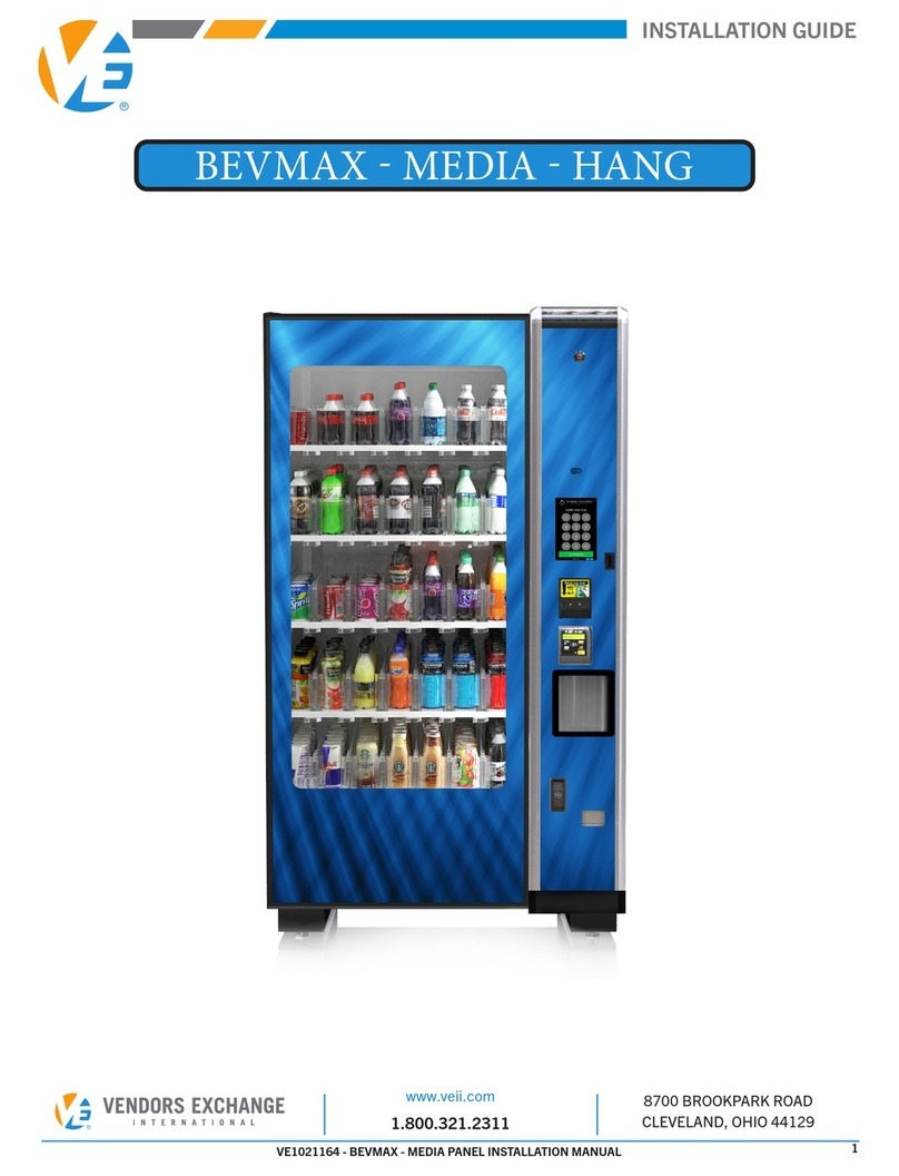
Vendors Exchange REVISION User manual

INSTALLATION GUIDE
What’s on These Pages
PRECAUTIONARY STATEMENTS................................................................................................... 3
TOOLS REQUIRED ........................................................................................................................ 4
SERVICE PARTS − DOOR............................................................................................................... 4
SERVICE PARTS − MOTORS .......................................................................................................... 4
SERVICE PARTS KIT − DOOR ........................................................................................................ 5
SERVICE PARTS − SPIRALS .......................................................................................................... 6
SERVICE PARTS − GLASS.............................................................................................................. 6
SERVICE PARTS − UCB™ .............................................................................................................. 6
SERVICE PARTS − LABELS............................................................................................................ 7
SERVICE PARTS − LED.................................................................................................................. 7
SERVICE PARTS − DROP SENSOR ................................................................................................ 7
SERVICE PARTS KIT – DROP SENSOR .......................................................................................... 7
DOOR OVERVIEWS – OEM ............................................................................................................ 8
DOOR OVERVIEWS – REVISION .................................................................................................... 9
REMOVE OEM DOOR AND PARTS............................................................................................... 10
INSTALL REVISION DOOR ........................................................................................................... 14
ATTACH AND ROUTE TRAY HARNESSES .................................................................................... 18
INSTALL VEND BUCKET.............................................................................................................. 20
INSTALL DROP SENSOR ............................................................................................................. 22
ADJUST THE DOOR .................................................................................................................... 24
UCB™ CONNECTIONS – NATIONAL............................................................................................ 25
PRODUCT WARRANTY ............................................................................................................... 28
2 REVISION™ Door for National 157/167 - 158/168
TABLE OF CONTENTS
To navigate this installation guide:
Click or touch each chapter title above to go directly to that section or pages and it will take you immediately to
that page via a hyperlink. Any pages with italicized words are links to other sections and pages and by clicking
or touching those links will also take you back and forth within this installation guide. The VE logos in the lower
corner of each page link back to the Table of Contents or the Door Overview Pages.

INSTALLATION GUIDE
3REVISION™ Door for National 157/167 - 158/168
PRECAUTIONARY STATEMENTS
WHAT THE SYMBOLS MEAN
WARNING, CAUTION, and
NOTICE
statements are used in this installation manual to stress important
and critical information to safely service this door. These statements, according to the American National
Standards (ANSI), are described below.
PLEASE READ THESE INSTRUCTIONS THOROUGHLY BEFORE INSTALLING
THE CURVE DOOR. IF YOU NEED ANY ASSISTANCE, CALL 1-800-321-2311
THIS SYMBOL INDICATES A HAZARDOUS SITUATION WHICH, IF NOT AVOIDED, COULD
RESULT IN DEATH OR SERIOUS INJURY.
THIS SYMBOL INDICATES A HAZARDOUS SITUATION WHICH, IF NOT AVOIDED, COULD
RESULT IN MINOR OR MODERATE INJURY.
THIS STATEMENT IS USED TO ADDRESS PRACTICES NOT RELATED TO PHYSICAL INJURIES
OR SITUATIONS THAT WILL NOT CAUSE HARM.
NOTICE
WARNING
CAUTION
R
Overview
R
To TOC

INSTALLATION GUIDE
4
TOOLS REQUIRED
SERVICE PARTS − DOOR
SERVICE PARTS − MOTORS
TO USE WITH OUTLINED PROCEDURES
REVISION™ Door for National 157/167 - 158/168
5/32” HEX
KEY
7/16” BOX
END WRENCH
PHILLIPS
SCREW-
DRIVER
FLAT HEAD
SCREW-
DRIVER
11/32” NUT
DRIVER
STANDARD
SOCKET SET
FLASHLIGHT WIRE/SIDE
CUTTERS
PART NUMBER DESCRIPTION
VE1529A DOOR SWITCH
VE4350N LOCK BAR
VE6816R1 KEY PAD
VE1015284 COIN CHUTE
VE3852C COIN RETURN BUTTON ASSEMBLY
PART NUMBER DESCRIPTION
NAT1577038 VEND MOTOR
R
Overview
R
To TOC

5REVISION™ Door for National 157/167 - 158/168
INSTALLATION GUIDE
PART NUMBER DESCRIPTION QTY.
VE1015506 WASHER, FLAT, .513 ID X .874 OD 2
VE3855 BOTTOM HINGE 1
VE4310P TOP MOUNTING NUT PLATE 1
VE4318 ITEM TABS 110−189 1
VE4319 GUM AND MINT TRAY HARNESS 1
VE1015284 COIN CHUTE 1
VE4350DX SWITCH CONTACT BRACKET 1
VE4350H BUCKET DEFLECTOR, CONTROL SIDE 1
VE4350LB LOCK BAR LATCH 2
VE4350Q DOOR BRACKET 1
VE9314 BUCKET DEFLECTOR, HINGE SIDE (INCL. W/ DROP SENSOR) 1
VE4653K 1/2 IN. BLACK NYLON CABLE CLAMP 4
VE4656 8 IN. CABLE TIE HOLDING CLIP 4
VE4849 ENERGY SAVING LED CLING ON LABEL 1
VE5876 REFUND CLING ON LABEL (IF DROP SENSOR EQUIPPED) 1
VE1017903 INSTRUCTION SHEET, UCB BOARD CLEAR AND DEX INT 1
VE1017759 UCB KEYPAD LEGEND 1
VE1018581 UCB PROGRAMMING FLOW CHART 1
VE5802G MOUNTING PLATE FOR POWER SUPPLY 1
VE1019011 POWER SUPPLY BOARD 1
VE5813A SCREW, PHILLIPS PAN HEAD, 4-40 X 1/4 IN. 4
VE6836 SCREW, CAP, FLAT HEAD, HEX SOCKET, 1/4-20 X 7/8 IN. 4
VE7203K NUT, HEX, #4-40 10
VE7358 LOCK NUT, KEPS, 1/4-20 1
VE7369 BOLT, HEX HEAD, 1/4-20 X 1 IN. 1
VE7373K SCREW, SELF-TAP, #8-18 X 1/2 IN. 10
VE5888A 110 V POWER HARNESS 1
VE8387THK VE8387 AND VE8387A HARNESS 1
VE8387 TRAY HARNESS 1
VE8387A ADAPTER TRAY HARNESS 1
VE1015729 POWER ADAPTER HARNESS 1
VE105231 INSTALLATION MANUAL 1
SERVICE PARTS KIT − DOOR
R
Overview
R
To TOC

INSTALLATION GUIDE
PART NUMBER DESCRIPTION
VE3424 SPIRAL, 6 COUNT CANDY–LH
VE3425 SPIRAL, 6 COUNT CANDY–RH
VA3281A SPIRAL, 9 COUNT SNACK–LH
VE3281B SPIRAL, 9 COUNT SNACK–RH
VE3280A SPIRAL, 11 COUNT SNACK–LH
VE3280B SPIRAL, 11 COUNT SNACK–RH
VE3455A SPIRAL, 15 COUNT SNACK–RH
VE3455B SPIRAL, 15 COUNT SNACK–LH
VE3840A SPIRAL, 17 COUNT SNACK–RH
VE3840B SPIRAL, 17 COUNT SNACK–LH
6 REVISION™ Door for National 157/167 - 158/168
SERVICE PARTS − SPIRALS
SERVICE PARTS − GLASS
PART NUMBER DESCRIPTION
VE3265 GLASS, 42.88” X 27.81” X 0.19” TEMPERED, 5 WIDE MODEL
VE3493 GLASS, 42.81” X 21.56” X 0.19” TEMPERED, 4 WIDE MODEL
SERVICE PARTS − UCB™
PART NUMBER DESCRIPTION
VE5801 UNIVERSAL CONTROL BOARD
VE5816 MDB HARNESS
VE5802C DISPLAY HARNESS
VED5866DF HARNESS BOARD FORCED
VE6451R1 DISPLAY BOARD
VE6820 DEX HARNESS
R
Overview
R
To TOC

INSTALLATION GUIDE
7REVISION™ Door for National 157/167 - 158/168
SERVICE PARTS − DROP SENSOR
PART NUMBER DESCRIPTION
VE6836 DROP SENSOR HARNESS
VE9300RTR REFLECTIVE TAPE (SPECIFY SIZE)
VE9300BN147 SENSOR BRACKET FOR NATIONAL DOOR
VE9300SBUSA2 BOARD, DROP SENSOR
SERVICE PARTS − LABELS
SERVICE PARTS − LED
SERVICE PARTS KIT – DROP SENSOR
PART NUMBER DESCRIPTION
VE4318 ITEMS TABS 110–189
VE3480 PRICE ROLLS, CENTS
VA3481 PRICE ROLLS, DOLLARS
PART NUMBER DESCRIPTION
VEL1410RD LED LIGHT BAR KIT, 3 LED
VE1410 LED LIGHT BAR, 1 LED
VE5829C LED MOTION SENSOR
PART NUMBER DESCRIPTION QTY
VE9300BN147 DROP SENSOR KIT (INCLUDES THE FOLLOWING) 1
VE5901AH DROP SENSOR HARNESS 1
VE9308A MAGNET 1
VE4650K 4 WAY TIE MOUNT 8
VE4601K 6” BAR LOCK CABLE 8
VE4679 1/8” CABLE CLAMP 1
VE7207K LOCK NUT, KEPS, #8-32 2
VE9314 PLASTIC DIVERTER, BENT 1
VE9300RTNAT REFLECTIVE TAPE 1-1/2 IN. WIDE X 6 IN. LONG 1
R
Overview
R
To TOC

INSTALLATION GUIDE
8 REVISION™ Door for National 157/167 - 158/168
DOOR OVERVIEWS – OEM
The blue hyperlinks below connect to the pages
where these features are described, click the
hyperlink to go directly to that page or click the
balloons below.
Inside Location of Top Hinge
and Mounting Plate
Inside Location of Vend Bucket and
Harnesses
Inside Location of Bottom
Door Hinge and Door Stop
Inside Locations of Coin Chute and Coin
Box
Inside Location of Coin
Mechanism
Inside Location of Card
Validator
Location of Touch Pad, Lens
Display and Display Board
and Machine Switch
7
7
5
5
4
4
3
32
2
1
1
6
6
R
To TOC

INSTALLATION GUIDE
9REVISION™ Door for National 157/167 - 158/168
DOOR OVERVIEWS – REVISION
The blue hyperlinks below connect to the pages
where these features are described, click the
hyperlink to go directly to that page or click the
balloons below.
Inside Location for Top Hinge
of the Door
Inside Location for Coin Chute
(A), Coin Funnel (B) and Cash
Box (C)
Inside Position for Power Supply Board
and Electrical Panel.
Inside Position where Coin
Mechanism is.
Inside Location of the Card
Validator
Inside location of UCB, Dis-
play Board and Door Switch
Inside Position of the Vend Buck-
et (A) and the Bottom Hinge (B).
7
7
5
5
4
8
4
8
3
3
2
2
1
1
6
6
A
A
B
B
C
R
To TOC

INSTALLATION GUIDE
10
REMOVE OEM DOOR AND PARTS
REVISION™ Door for National 157/167 - 158/168
REMOVE OEM DOORINSTALL DOORHARNESSINGINSTALL BUCKETDROP SENSORADJUST DOOR
If equipped with an OEM Gum and Mint tray, use a 3/8” nut
driver or socket set, remove (2) bolts, one on each of the
Vend Bucket.
If present, remove the validator and coin
mechanism. If they are MDB, set them aside for
future installation.
Disconnect the gum and mint tray harness from jumper board
on tray motor mount at the bottom of the Vend Bucket.
Using a 1/4” nut driver or socket set on the top screw, remove the bucket
deflector on the left side of the Vend Bucket. Use 11/32” nut driver or socket
for two side screws.
1
3
2
4
TO AVOID POTENTIAL
INJURY, IT IS HIGHLY
RECOMMENDED THAT
THE CURVE DOOR IS
INSTALLED BY TWO
QUALIFIED INSTALLERS
DO NOT REMOVE THE
TRAYS FROM THE
CABINET. THE CABINET
COULD BECOME
UNSTEADY AND RESULT
IN DAMAGE OR
PERSONAL INJURY
TO PREVENT
PERSONAL INJURY AND
EQUIPMENT DAMAGE,
TURN MACHINE OFF
AND DISCONNECT
ELECTRICAL CORD FROM
THE WALL OUTLET TO
PREVENT ELECTRICAL
SHOCK
TEST THE MACHINE THAT
IT IS WORKING ORDER
BEFORE REPLACING THE
DOOR. SERVICE SHOULD
BE PERFORMED BY
QUALIFIED PERSONNEL
NOTICE
WARNING WARNING CAUTION
Screws on Left Side
Gum and Mint Tray
Screws Holding
Gum and Mint
Tray
Vend Bucket
Jumper Board
(Continued next page)
Card Validator
Deflector
Harness
R
Overview
R
To TOC

INSTALLATION GUIDE
REMOVE OEM DOORINSTALL DOORHARNESSINGINSTALL BUCKETDROP SENSORADJUST DOOR
11
REMOVE OEM DOOR AND PARTS
REVISION™ Door for National 157/167 - 158/168
REMOVE OEM DOOR INSTALL DOOR HARNESSING INSTALL BUCKET DROP SENSOR ADJUST DOOR
Remove bucket guard at the top of the Vend Bucket by loosening
(2) screws on left and right side.
Using a 7/16” nut driver or socket, remove door
stop from bottom of door. Set aside to install on
REVISION door.
Lift up and remove the door.
Using a 7/16” socket, remove the top hinge from inside the door (left). A flat
head screwdriver may also be required (right).
5 6
7
9
8
Right Side
Vend Bucket
Then, remove the screws holding Vend Bucket to the door on
both sides. Up to (4) screws could be fastened to each side.
Remove the OEM Vend Bucket from the door.
(Continued next page)
CAUTION
USE AN ADDITIONAL
PERSON WHEN
REMOVING THE DOOR TO
PREVENT INJURY TO THE
INSTALLER AND DAMAGE
TO THE EQUIPMENT
Vend Bucket
Linkage
Socket Wrench
Door Stop Arm
Bottom of Door
Top of Door
CAUTION TO AVOID PERSONAL INJURY, MAKE SURE
THE OEM DOOR IS SUPPORTED
Socket Wrench
Left Side
Bucket Guard
R
Overview
R
To TOC

INSTALLATION GUIDE
12
REMOVE OEM DOOR AND PARTS
REVISION™ Door for National 157/167 - 158/168
Disconnect door switch harness from door
switch as shown.
Open swing panel and unfasten flat head screw from the display board
cover. Then, remove top ribbon cable only and metal strap.
Loosen nuts in (6) places from swing panel, then remove the
swing panel from the cabinet.
Loosen 1/4” screws and remove the bracket from right side of
the cabinet.
12
13
1110
(Continued next page)
REMOVE OEM DOORINSTALL DOORHARNESSINGINSTALL BUCKETDROP SENSORADJUST DOOR
Door Switch
Display Board
Cover
Display Board
Swing Panel
Top Ribbon
Cable
Screw
Screws (6)
Screws (3)
Screws (3)
Screws (3)
Bracket
Harness
R
Overview
R
To TOC

INSTALLATION GUIDE
13
REMOVE OEM DOOR AND PARTS
REVISION™ Door for National 157/167 - 158/168
Remove coin chute screws from existing cash box housing
and cabinet.
Remove all harnessing from controller and interface boards.
Save standos and hardware from both boards and set aside
for future installation of power supply board.
Loosen 1/4” screws from top and bottom of panel and lift o.
Then, using a Phillips or flat head screwdriver (depending on
machine), remove the (4) screws that hold (2) OEM lock bar
latches in place.
14
16
15
17
NOTE: It is recommended to retain all “P” shaped clamps
for future use to secure new wiring with new controller
assembly, and to maintain a cleaner application.
REMOVE OEM DOOR INSTALL DOOR HARNESSING INSTALL BUCKET DROP SENSOR ADJUST DOOR
Controller Board
Pay Side of the
Cabinet
Interface Board
Cash Box
Screws (2)
Coin Chute
OEM Lock Bar
R
Overview
R
To TOC

INSTALLATION GUIDE
14
INSTALL REVISION DOOR
REVISION™ Door for National 157/167 - 158/168
First, install new replacement Lock Bar Latches (VE4350LB) open end
up with Phillips screws (VE5318A) as shown.
Then, using a 5/32” hex key, Mount Nut Plate (VE4310P) and Bottom Hinge (VE3855) to door with Hex Screws (VE6836) as
shown. Use detail as a guide for proper mounting position.
Then, align (2) Flat Washers (VE1015506) over the hole on the bottom of the bracket. Then, insert the Bottom Hinge (VE3855) into
the bottom bracket hole.
1
2
3
SECTION 1. INSTALL DOOR MOUNTING
NOTE:
Latches are adjustable to ensure proper clos-
ing and locking of the door. Multiple attempts
may be necessary to determine the exact
adjustment.
The top hinge is fix mounted to the cabinet.
Original Equipment Manufacturer (OEM)
hinge is used and no installation is required.
Detail of Hinge Mount
Top View
Bottom View
Open to 90º
Open to 90º
(Continued next page)
REMOVE OEM DOORINSTALL DOORHARNESSINGINSTALL BUCKETDROP SENSORADJUST DOOR
Lock Bar Latch
Screws
Bottom Hinge
Bottom Hinge
Bottom of
Door
Mount
Nut
Plate
Screws
Mount to this
hole inside
door
Mount Nut Plate
Bottom Hinge
Screws
Bottom of Cabinet
Align Washers
R
Overview
R
To TOC

INSTALLATION GUIDE
15REVISION™ Door for National 157/167 - 158/168
INSTALL REVISION DOOR
Next, hold doors so holes on the top align with hinge holes. Then, using a
5/32” hex key, fasten Top Nut Plate (VE4310P) on inside top of the door
while screwing in Flat Head Screws (VE6836) as shown.
Next, insert door stop arm in door stop bracket
as shown.
Mount door stop spacer onto the door stop arm. Then insert bolt through spacer and bottom hinge plate. Attach nut to bolt and hand
tighten with 7/16” box wrench.
Open and close door to verify fit. Remove gum and mint support bar from OEM door and hang on hinge side of
the REVISION door.
SECTION 2. DOOR COMPONENTS
4 1
2
3 4
(Continued next page)
REMOVE OEM DOOR INSTALL DOOR HARNESSING INSTALL BUCKET DROP SENSOR ADJUST DOOR
Hex Key
Top Nut Plate
Screws
Door Stop Bracket
Door Stop Arm
Door Stop Spacers
Door Stop Arm
Saved Bolt
Box Wrench
Gum and Mint Support Bar
Open/Close Door
R
Overview
R
To TOC

INSTALLATION GUIDE
16 REVISION™ Door for National 157/167 - 158/168
INSTALL REVISION DOOR
Next, fasten Coin Chute (VE1015284) to OEM cash box
housing.
Then, insert (3) standos removed from previous interface
board mounting holes as shown. NOTE: Can also be installed
directly onto power supply board.
Next, position and mount the Power Supply Board (VE5815)
onto the standos as shown.
Next, connect the power cable from the Cabinet Harness
(VE1015729) to power supply board as shown.
Then, fasten machine screw set aside from previous step to
the upper left stud on power supply mounting plate.
If note above is true, from inside cabinet, remove cover from
main power supply
5
7
9 10
6
8
SECTION 2. DOOR COMPONENTS (continued)
NOTE: If OEM power supply
DOES NOT include harness to
connect with new power supply,
follow steps 10–15.
(Continued next page)
REMOVE OEM DOORINSTALL DOORHARNESSINGINSTALL BUCKETDROP SENSORADJUST DOOR
Inside Front of
Cabinet
Position as
shown towards
top of cabinet
Inside Front of
Cabinet
Coin Chute
Cash Box
Stand-Os
Fasten Screw
Power Supply
Power Supply
Cabinet Harness
Cabinet Harness
Power Supply
Cover
R
Overview
R
To TOC

INSTALLATION GUIDE
17REVISION™ Door for National 157/167 - 158/168
INSTALL REVISION DOOR
Next, disconnect existing power harness as shown. Then, connect the Power Adapter Harness (VE1015729) to
the male connector as shown.
Next, guide harness through the opening as shown above on
the left image. Then, route harness upward behind cabinet
weldment and push through cutout as shown in right image.
Next, from inside the cabinet, re-install the cover to the main power supply (left, right
images). Ensure that all wires are not pinched and are contained behind the main
power supply cover.
Then, connect the female end of the power adapter harness
from the rectangular cutout to the power supply board
connector as shown.
11 12
13 14
15
SECTION 2. DOOR COMPONENTS (continued)
THIS SECTION IS COMPLETE,
MOVE TO HARNESSING ON THE
NEXT SECTION
REMOVE OEM DOOR INSTALL DOOR HARNESSING INSTALL BUCKET DROP SENSOR ADJUST DOOR
Power Adapter Harness
Male Connector
Power Adapter Harness
Panel Hole
Panel Cutout
Power Supply
Power Adapter Harness
Connections
R
Overview
R
To TOC

INSTALLATION GUIDE
18 REVISION™ Door for National 157/167 - 158/168
ATTACH AND ROUTE TRAY HARNESSES
First, uncoil harnesses and separate longer cabinet harnesses
and prepare longer harnesses to be routed into the cabinet.
Next, wind green ground wire around main door harness at
least 6 to 8 times. Then, secure the main door harness to in-
side of the cabinet with Cable Clamp (VE4653K) and Screw
(VE7373K). Then connect ground wire to inside of cabinet.
Next, route door harness on side of cabinet as shown.
Using Cable Clamps (VE4653K) and self-tapping Screw
(VE7373K).
Next, pull the power supply cable through the cutout, then
connect 24 V power supply to power supply board.
Then, continue routing door harness on the side and on
the back to other side of cabinet using (VE4653K) and
(VE7373K). Guide door harness toward power supply side of
machine and then through cutout.
Then, connect (2) tray harnesses from main door harness to
existing door harnesses. Ensure that connector pins tabs are
in the same direction on both plugs.
1 2
3
5 6
4
NOTE: Connector wire
colors may vary due
to dierent machines
and components.
REMOVE OEM DOORINSTALL DOORHARNESSINGINSTALL BUCKETDROP SENSORADJUST DOOR
24V
(Door)
Gum/Mint
(Door)
Motor
(Cabinet)
Drop Sensor
(Door)
1
2
2
1
3
4
4
3Ground Wire
Cable Clamp with
Screw
Cable Clamp and
Screw
Ground Wire
Connected
Inside Cabinet
Inside Cabinet
Cable Clamp and
Screw
24V Power
Supply Harness
Connection
Point on Power
Supply
R
Overview
R
To TOC

INSTALLATION GUIDE
19REVISION™ Door for National 157/167 - 158/168
ATTACH AND ROUTE TRAY HARNESSES
Finally, replace the screws set aside from before on the top
and bottom of the panel
7
NOTE:
Make sure all harnesses are clean and clamped properly
for a presentable appearance when opening the door.
Ensure that the electrical panel cover is not pinching any
wires.
REMOVE OEM DOOR INSTALL DOOR HARNESSING INSTALL BUCKET DROP SENSOR ADJUST DOOR
THIS SECTION IS COMPLETE,
MOVE TO INSTALL VEND BUCKET
ON THE NEXT SECTION
R
Overview
R
To TOC

INSTALLATION GUIDE
20
INSTALL VEND BUCKET
First, if using a National 168 Vend Bucket, loosen the filler mount attached to the hinge side of the REVISION door, the 168 bucket
has a wider profile and does not require a filler mount.
REVISION™ Door for National 157/167 - 158/168
Next, center the bucket in the opening, aligning mounting holes on door with mounting holes on the Vend Bucket.
Then, use self-tapping screws (VE7373K) to fasten the Vend Bucket on left and right side at the top and bottom.
1
2
3
NOTICE
IT IS RECOMMENDED THAT THE
INSTALLATION OF THE VEND
BUCKET IS COMPLETED WITH AN
ADDITIONAL PERSON TO ASSIST
WITH POSITIONING AND
ALIGNING THE BUCKET
TO PREVENT DAMAGE OR
PERSONAL INJURY, DO NOT
DROP THE BUCKET
(Continued next page)
CAUTION
REMOVE OEM DOORINSTALL DOORHARNESSINGINSTALL BUCKETDROP SENSORADJUST DOOR
Curve Door
Filler Mount
for National
168 only
Filler
Mount
Door View
Loosen these
screws
Vend Bucket
Left Side Hole Location
R
Overview
R
To TOC
Table of contents
Other Vendors Exchange Vending Machine manuals
Popular Vending Machine manuals by other brands
Fastcorp
Fastcorp F820 Service and parts manual

Magic Play
Magic Play Lollipops instructions

SandenVendo
SandenVendo SVE C36-XS User and maintenance manual

LAVAZZA
LAVAZZA LB3200 Colibri manual

Hamilton Manufacturing Corporation
Hamilton Manufacturing Corporation Token Vendor Operational manual

Crane
Crane Linea user manual

Bianchi
Bianchi REPARTO CORSE SADDLE Use and maintenance manual

Seaga
Seaga Intelligent Inventory Control IQ640 Service and parts manual

Westomatic
Westomatic Elevate quick start guide

Jofemar
Jofemar Coffeemar G-250 Technical manual

Saeco
Saeco Group 500 Instruction and maintenance manual

Vendo
Vendo RSC Assembly & installation