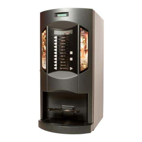
Rheavendors Group SAGOMA Manual

Manual CE (SAGOMA GB)
automatic vending machine
[SAGOMA]
installation and maintenance manual
to be kept inside the machine
MAN3100005
Vers 1.0 22/11/2002

Manual CE (SAGOMA _GB)
LCD
DISPLAY
SELECTION
KEYPAD
COIN
ENTRY
LOCK
CUP
STATIONY
COIN
RETURN
2/2

Manual CE (SAGOMA_GB)
INDEX
SEZIONE 1 TECHNICAL DATA ......................................................................................................................... 4
SEZIONE 2 PART 1. INTRODUCTION.............................................................................................................. 5
SEZIONE 3 PART 2. DESCRIPTION OF THE EQUIPMENT......................................................................... 7
SEZIONE 4 PART 3. ADVICE FOR THE INSTALLER ................................................................................... 8
SEZIONE 5 PART 4. BASIC OPERATING PRINCIPLES ............................................................................... 9
SEZIONE 6 PART 5. TRANSPORTATION ...................................................................................................... 13
SEZIONE 7 PART 6. UNPACKING ................................................................................................................... 13
SEZIONE 8 PART 7. POSITIONING................................................................................................................. 14
SEZIONE 9 PART 8. CONNECTION TO THE MAINS WATER SUPPLY AND TO THE ELECTRICAL
SUPPLY 16
SEZIONE 10 PART 9. HOW TO ACTIVATE OR DESACTIVATE THE MACHINE.................................. 17
SEZIONE 11 PART 10. START-UP OPERATIONS .......................................................................................... 19
SEZIONE 12 PART 11. PROGRAMMING OF THE MACHINE..................................................................... 27
SEZIONE 13 PART 13. INSTALLATION OF THE PAYMENT SYSTEMS................................................... 48
SEZIONE 14 PART 14. CLEANING AND LOADING OPERATIONS ........................................................... 49
SEZIONE 15 PART 15. ORDINARY AND PREVENTION MAINTENANCE ............................................... 54
SEZIONE 16 PART 15. MACHINE OUT OF SERVICE ................................................................................... 56
SEZIONE 17 PART 17. FURTHER ADVICE FOR THE USER ....................................................................... 57
SEZIONE 18 PART 18. TROUBLESHOOTING................................................................................................. 58
3/3

Manual CE (SAGOMA _GB)
Sezione 1 Technical Data
DIMENSIONS
Height 1830 mm
Width 625 mm
Depth 500 mm
WEIGH
From 95 to 115 Kg according to the version
CONNECTION TO THE MAIN WATER SUPPLY
Water inlet pressure between 1 and 8 bar:
mains water connection 3/8” gas female
CONNECTION TO THE ELECTRICAL SUPPLY
230 V ∼50 Hz;
Power consumption between 1300 W and 2000 W
According to the version.
1.1 Copyright Information
© M.P.R. - All rights reserved.
This document contains confidential information, which is property of M.P.R. The content of this document cannot be neither circulated
to third parties, nor copied or duplicated in any form, without previous written consent by M.P.R. Use, duplication or divagation of
technical information contained in this document can be subject to legal protection by M.P.R., via Trieste 49, I-21042 Caronno Pertusella
(VA), Italia.
THIS MANUAL MUST BE KEPT INSIDE THE MACHINE.
Installation and maintenance manual Automatic Vending Machine SAGOMA
INCOLLARE QUI LA SECONDA COPIA
DELL'ETICHETTA MATRICOLA
Identification sticker of your machine
4/4

Manual CE (SAGOMA_GB)
Sezione 2 Part 2. Introduction
We congratulate you on your choice of a M.P.R. automatic vending machine. This product has
been designed by experts and it has been manufactured according to the high quality standards,
which have always been a characteristic of all M.P.R. products. This instruction manual will help
you to acquire a better knowledge of your machine. We recommend you to read it with the
maximum attention and to follow the advice given in the text.
The present manual includes all information and instructions for loading and cleaning
operations of the vending machine, as well as instructions reserved to technical personnel
for performing maintenance operations of more complex nature. This is the reason why the
manual pages are clearly identifiable with relation to the technical preparation of the user to
whom they are destined:
Text with grey background: for any person having access to the interior of the vending machine.
These pages consist of an introduction, sections of general interest and sections concerning
loading and routine cleaning.
Text with normal background:these are for use by qualified technical personnel only. They
include all operations related to installation, adjustment, and extra ordinary cleaning and
general maintenance.
All information contained in this manual are aimed to obtain from the machine the best
performance within the limits of use set by the manufacturer.
This Manual is integral to the equipment and must be available inside the machine until final
deplacement. Inside the rear door of the machine there is a suit0able pocket where the Manual
should be kept.
In the event of loss or damaging of the Manual, to obtain an extra copy it will be necessary to
supply to the manufacturer all the identification data appearing on the identification sticker.
In compliance with the Company's endeavour to adopt technical improvements whenever possible,
M.P.R. reserves the right to ameliorate future production (and the contents of future Manuals)
without prior notice and without any obligation of updating the products on the market.
The Technical service department of M.P.R. is at your disposal for any further information. Just call
or send a fax at the following numbers:
+39.02.966551
+39.02.9655086
or surf our web site www.rheavendors.com or send en e-mail at the address
In order to speed up the response to your requests it will be necessary to supply:
- All data appearing on the Serial Number Label (glued to the first page of this manual).
- If the display of the machine is equipped with 2 buttons and led for sugar adjusting.
CAUTION: M.P.R. is not liable for any damage that could affect, directly or indirectly, any
person or property as a consequence of:
- Incorrect use of the vending machine.
- Incorrect installation.
- Unsuitable electrical or water supply.
- Major shortcomings in maintenance.
- Technical interventions or alterations of unauthorised nature.
- Adoption of non-original spare parts.
In the event of breakdown, M.P.R. has got no obligation whatsoever neither to compensate any
economical damage deriving from the inactivity of the machine nor too extend the warranty period.
5/5
Manual CE (SAGOMA _GB)
2.1 Safety Regulations
The vending machine has been designed and manufactured in accordance with the following
European Regulations:
Directives 73/23 CEE; 98/37/CE; 89/336/CEE
Norms EN 60335-1
IEC 60335-2-75
EN 5514-2:1997
EN 61000-3-2:1995+A1:1998+A2:1998
EN 61000-3-3:1995
EN 55014-1:1993+A1:1997
6/6

Manual CE (SAGOMA_GB)
Sezione 3 Part 3. Description of the Equipment
3.1 Use
The SAGOMA Vending Machine, in its different models, is an appliance meant for general use
(non-professional).
The Vending Machine is supposed to supply beverages automatically, mixing ingredients with
water.
The distribution of beverages will take place into suitable cups automatically supplied by the
machine itself. In the models with Espresso Coffee group, the machine will also automatically
dispense stirrers for beverage mixing.
3.2 Denomination of the models
M.P.R. adopts the following conventional codes for the definition of the different versions:
SAGOMA <coffee>/<canisters> [<cold>] [<options>]
where:
<coffee> states the main process for the preparation of coffee:
H.…… Instant coffee (from soluble products)
E...…. Infusion process through a high pressure Espresso coffee group
FB...…Infusion process through a low pressure filtered coffee group
<canisters> states the number of product canisters except the one for coffee beans.
Capacity and variety of types of beverages that can be supplied by the vending machines
will depend on this number.
<cold> states the sort of cold beverage obtainable from the machine (if a refrigeration group is
present)
FP.....beverages from powdered products (with natural water).
3.3 Obtainable Beverages
All beverages obtainable from your machine are shown in the list attached to this manual, and they
vary substantially according to the version of the machine.
7/7

Manual CE (SAGOMA _GB)
Sezione 4 Part 4. Advice for the installer
Installation and maintenance operations described in the white papers must be carried out
only by qualified technical personnel.
Use only specific ingredients for automatic vending machines.
For a correct operation, the machine must be installed indoor with operating temperature higher
than 5° C in normal conditions of use.
WARNING: given the sensitivity of some ingredients used in the machine to excessive
temperature and humidity, some malfunctions may occur if the machine is operated at
temperature higher than 30° C or with relative humidity exceeding 80%.
The SAGOMA vending machine, that you have bought, has been manufactured according to the
norms and regulations related to the non-toxicity of those parts coming in contact with foodstuffs
and electric insulation. The machine is mounted inside of an industrial cleaned ambient. The
person entrusted with the mounting and the test operations is subjected to frequent sanitary
examinations to confirm his attitude. However, freight conditions, period of stay in the warehouse
and possible handling due to the installation of the vending machines do not allow using it
immediately.
The vending machines, before its use, must be subjected to a cycle of sanitary tests as per the
instructions shown in paragraph “Cleaning and disinfecting of those parts coming in contact with
foodstuffs”.
Under these conditions the components in contact with the powdered ingredients must be cleaned
at least once a day.
Installation in premises where water jets are used (e.g. large kitchens) is to be avoided.
The personnel in charge of the loading of the ingredients must own a valid certificate of good
health. Furthermore, compliance with any other domestic or local regulations must be checked.
8/8

Manual CE (SAGOMA_GB)
Sezione 5 Part 5. Basic Operating Principles
The powered machine is normally in the stand-by mode. When a button is pressed, a vend cycle
starts. If a sale price is pre-set (i.e. the machine is not pre-set for the free vend mode), before
selection the required amount of money must be inserted by means of coins, bank notes or other.
According to the selection required and to the model of the machine, the vend cycle is composed
by some of the following procedures.
5.1 Dispensing and positioning of the cups
If it is not disabled by pressing the special prebutton "Without cup" (if
available), this procedure is carried out before all vend operations are
started.
Through the action of the unclamping servomotor, the cup is detached
and falls in the appropriate support;
5.2 Dispensing of sugar
This supply is pre-set only for the models of machine equipped with the sugar dispensing group
(models E) in the event sugared beverages being selected. For the other models, always when the
beverage requires it, the sugar is dispensed simultaneously with the preparation of the instant
beverages and with the same procedure (see after).
1) The geared motor activates the screw
feeder in the sugar canister which
pours the correct quantity of sugar in
the dispensing unit;
2) The servomotor of the dispensing unit causes
the slide movement and the following pouring
of the sugar in the cup.
5.3 Preparation of hot beverages from soluble ingredients
This procedure is usually carried out after the cup is correctly positioned under the outlet pipes of
the beverage. More than one procedure of this sort can be carried out simultaneously or in
sequence during a vend cycle.
1) Only in Version Ethe pump which loads water inside the water refilling tank is activated;
9/9

Manual CE (SAGOMA _GB)
2) When the solenoid valve corresponding to the boiler is activated, the preset quantity of water is
poured to dissolve the ingredients;
3) If supplied, the mixer motor is activated;
4) The geared motor activates the screw feeder, in the canister of the corresponding ingredient,
which pours the correct quantity of ingredient in the mixing bowl. More than one canister of
ingredients can be activated simultaneously for the same mixing bowl;
5) If present, the motor of the mixing bowl is switched off;
6) The solenoid valve correspondingl is switched off.
5.4 Preparation of the espresso coffee
This procedure is carried out only in the models equipped with the espresso coffee group (Version
E) and after the cup is correctly positioned under the outlet pipes of the beverage. The execution
priority between this procedure and the procedure for the preparation of hot beverages from instant
ingredients is pre-set by the programme of the machine and varies according to the selection
chosen.
1) The coffee grounds are ejected (this can occour also after 10 minutes of rest of the micro
coffee group) and the group moves to receive the coffee dose;
2) The electromagnet of the coffee
throw dispensing unit is activated and
the canister is open. The correct
quantity of ground coffee flows by
gravity in the brewer of the espresso
coffee group; *
3) The coffee grinder is activated until the pre-
set quantity in the throw dispensing unit is
restored;
4) The coffee group moves to the infusion 5) The water coming from a water refilling tank,
10/10

Manual CE (SAGOMA_GB)
position: this occurs when the group
movement motor is started. The lower filter
is moved to close the brewer and press the
preset throw the compress of ground
coffee; *
in which the water level is kept constant, is
conveyed by pressure in the coffee boiler by
means of a pump. After the activation of a
solenoid valve, the same quantity of warmed up
water is then conveyed to the coffee group.
6) The coffee group ends the cycle.
* The operations marked with asterisk may be carried out in a different order according to the
electronic presetting of the machine.
5.5 Preparation of filter coffee
This procedure is carried out only in the models equipped with a coffee brewing group (models
FB), after the cup has been correctly positioned under the outlet pipes for the beverage vending.
The execution priority between this procedure and the procedure for the preparation of hot
beverages from instant ingredients is pre-set by the programme of the machine and varies
according to the selection chosen.
1) The geared motor activates a screw feeder, which pours the pre-set quantity of ground coffee
into the coffee group;
2) The coffee group moves to brewing position: this occurs when the group movement motor is
started. The upper filter moves upwards to close the brewer and press the pre-set quantity of
ground coffee;
3) The water coming from a water-refilling tank means of a pump. After the activation of a
solenoid valve, the same quantity of warmed up water is then conveyed to the coffee group.
4) The coffee grounds are ejected and the group returns to rest position: this occurs when the
group movement motor is started. The upper filter moves and opens the brewer. The coffee is
ejected by the combined action of the lower filter and the ejection blade.
5.6 Dispensing of the stirrer
This procedure is carried out only in models equipped with stirrer feeder (Version E), and it is
carried out when the cup is correctly positioned under the outlet pipes for the beverage vending.
The stirrer can be dispensed before or after the preparation of a beverage, according to the
machine programme and selection made. Furthermore, a programmable function allows the user
to pre-set selections for which the stirrer is to be dispensed.
1) The unclamping electromagnet detaches the stirrer from the stack in the feeder. The stirrer
slides in the cup.
5.7 Preparation of cold instant beverages
This procedure is carried out only in the models of machine equipped
with the refrigerating group for natural water (Version FP), usually
when the cup is positioned under the outlet pipes for the beverage
vending.
1) The water inlet solenoid valve is activated to load water inside the
cold unit;
2) The corresponding solenoid valve in the refrigerating group is
activated and the correct quantity of water is poured into the
mixing bowl to dissolve the ingredients;
3) If present, the mixing bowl is activated;
11/11
4) The geared motor activates the screw feeder of the canister of

Manual CE (SAGOMA _GB)
the corresponding ingredient, which conveys the correct quantity of ingredient into the mixing
bowl. More than one canister can be activated simultaneously for the same mixing bowl;
5) The solenoid valves are switched off;
6) If present, the mixing bowl motor is switched off.
12/12

Manual CE (SAGOMA_GB)
Sezione 6 Part 6. Transportation
The machine must be moved by qualified personnel.
The machine must be carefully transported as any overturning of the
machine is to be avoided.
The machine must be kept horizontally positioned when moved to
another location.
The machine is supplied on pallet. It must be moved on a dolly, at
reduced speed and preventing any excessive bending movement of
the machine.
Sezione 7 Part 6. Unpacking
The machine must be unpacked as follows:
1) Cut the protection film
along one of the protection
angle bar around the
machine
2) Remove the pallet
from the machine by
lifting the two lateral
hooks;
3) Take the key on the rear
of the machine, near the
power supply cord.
WARNING: the packing materials must be kept out of the reach of unauthorized people,
specially children, as potentially hazardous. The disposal of special packing materials must
be carried out by qualified waste recovery companies.
- Open the door and remove the adhesive tape from:
- the feeder cup cover - the drops tray - the weight of the stirrer
feeder (Version E)
13/13

Manual CE (SAGOMA _GB)
Remove the board prism positioned
between the canisters of the
ingredients and the top of the
cabinet.
Sezione 8 Part 8. Positioning
The machine must be installed indoor on a flat and sound floor. If the machine is installed in a
safety gangway, the remaining opening of passage between the machine with the open door and
the nearest obstacle must be at least 80 cm.
Anchor the machine to the rear wall as follows:
- loosen the two screws which lock the fixing bracket on the machine cover;
- turn the bracket by 180° and fit it again to the machine by means of the appropriate screws
previously removed;
- move the machine near the wall until the bracket rests against the wall;
- regulate the feet placed under the machine for a correct levelling: there must be less than 2°
offset of the machine vertical axis with respect to the vertical axis of
the wall;
- drill the wall with a diameter 8 mm pin, using the bracket as drilling
template;
- fix the bracket to the wall by means of the screw anchors supplied in
the waste disposal bucket.
M.P.R. declines all responsibility for any shortcomings caused
by non compliance with installation instructions.
If the machine is installed on delicate or valuable floors, it is advised
to lay a carpet under the machine, about 80 cm larger than the
machine itself, made of rugged material, resistant to dirt and water
(e.g. synthetic laminate). This is to protect the floor and also prevent
it to get dirty for the accidental spilling of beverages.
A schematic general lay-out is indicated in the figure.
14/14

Manual CE (SAGOMA_GB)
15/15

Manual CE (SAGOMA _GB)
Sezione 9 Part 9. Connection to the mains water supply and to the electrical supply
9.1 Connection to the mains water supply
Before proceeding to the connection carry out the following checks on the water to be used:
- Make sure that the water supply is of drinking quality possibly through certificate of a laboratory;
- Make sure that water mains pressure ranges from 1 to 8 bar;
- If the mains pressure is lower than 1 bar, a pump must be installed;
- If the mains pressure is higher than 8 bar, a pressure reducer must be mounted, calibrated at 3
bar, on the water connecting hose of the machine; in any case the mounting of a pressure reducer
is advisable in all installations where high pressure peaks occur.
If not already existing, install a 3/8" gas tap to exclude the machine from the mains source in case
of emergency.
Connection of the tap to the machine must be made with a copper or plastic hose, which has been
approved for food contact use and resistant to operating pressure not lower than 10 bar.
Make sure that the water is free of impurities and does not feature excessive hardness (higher than
20 French Degrees). This shortcoming can be solved using normal water softeners. The SAGOMA
machines, models Eand FB, are complete with a standard water-
softening filter. The models Hcan be provided with an optional filter.
Lime scale can be notably reduced by the use of the filter, ensuring a
longer life of all components in contact with water and reducing
maintenance.
Carry out the connection on the inlet coupling of the water softener
or, should the filter not be mounted, directly on the inlet coupling of
the water inlet solenoid valve.
The water softener and the water inlet solenoid valve are both
provided with a 3/8" gas male inlet coupling.
If a water softening filter is mounted, the water hardness must be
taken (special kits are available for sale) in order to define how often
the filter shall be regenerated. This depends on the rate of use of the
filter and on the grade of water hardness (see section "Regeneration
of the water softener filter").
9.2 Connection to the electrical supply
Make sure that the grounding of the electrical mains to which the machine
will be connected is in good conditions and in compliance with domestic
and European standards concerning electrical safety.
The machine is equipped with a power supply cord H50VV-F 3x1.5 mm2
with Shucko plug.
Make sure that the electrical mains voltage is the same as indicated on
the identification sticker of the machine and that the current rating of the
plug is suitable for the current absorbed by the machine. The identification
sticker is put inside the machine and can be seen opening the door. For
connection, an electric plug, single-phase, 230V 50 Hz, for a maximum
load of 15A is required.
Any type of plug, which is incompatible with the socket of the machine,
must be replaced.
Do not use adaptors or multiple plugs.
16/16

Manual CE (SAGOMA_GB)
Sezione 10 Part 10. How to activate or desactivate the machine
10.1 Safety switch
A safety switch is provided in the machine which cuts the power off all
electrical and electronic components in the machine when the door is
opened.
If required, to switch the machine off open the door of the machine
or unplug it from the electrical mains.
Some operations will require to have the machine switched on and with
the door open. To activate the machine with the door open, when
specified in the instructions, insert the special plastic key, hanging on a
cord near the switch and turn it clockwise by 90°.
WARNING: the opening and switching on of the machine with the
door open (unless for cleaning operations) must be carried out
only by authorised, qualified personnel. Do not leave the machine
open unguarded.
10.2 Diagnostics cycle of the switching up
When the safety key is inserted, the machine carries out a diagnostics cycle to check the position
of the mobile components, the correct quantity of some ingredients and the correct water mains
supply pressure. The display shows:
rheavendors
03-2002
date of the last upgrade of the software loaded in the vending machine
SAGOMA
v 2.2 22 - 07 - 02
version of the master file loaded in the vending machine (i.e vers. 2.2)
vers. slave 1.m
- - - - - - - - - - - - - - - - -
version of the slave file loaded in the vending machine (i.e vers. 1.m)
PLEASE WAIT - - - - -
- - - - - - - - - - - - - - - - -
check coffee brewer
Only for versions E
At the end of checks, the standard invitation message will appear on the display, e.g.:
17/17

Manual CE (SAGOMA _GB)
rheavendors
SAGOMA
TAKE A RELAX
MOMENT
During the installation procedure, the following messages are displayed:
WATER REFILLING
meaning that some functions of the machine are temporarily inhibited for an easier and safe
installation. In these phases, these messages replace the standard invitation message. In case of
doubt, refer to installation instructions.
18/18

Manual CE (SAGOMA_GB)
Sezione 11 Part 11. Start-up operations
11.1 Installation - Phase 1
The phase 1 of the installation of the vending machine contains the water loading of the boiler
(Version H) or of the water refilling tank (Version E) and the setting of the temperature of the
boiler.
11.1.1 Loading the boiler of instant beverages
This operation is carried out on all models of the machine.
Place the liquid waste disposal bucket on the bottom of the machine,
sliding it in the appropriate guide tracks, and insert the drain pipes,
the pressure relief tube and the coffee brewer pipe (Version E).
Open the tap of the water circuit.
Insert the key in the safety switch. After the switching on messages,
the display shows:
WATER REFILLING
The machine starts automatically loading the boiler for instant
beverages with water (Version H); for espresso vending machines
loads first the water refilling tank and then the boiler (Version E). The
boiler is filled up in about 3 min.
The following message appears on the display:
rheavendors
SAGOMA
TAKE A RELAX
MOMENT
If the load is sufficient, by pressing the key PL inside the machine on the CPU protection, it is
necessary to make some washings of the mixing bowls and of the coffee brewer (Version E). The
display shows:
19/19

Manual CE (SAGOMA _GB)
WASHINGS
1 2 3 4
(Version H) Pressing buttons 1,2, 3and 4the machine pours water
from one of the beverage outlet spouts. Press the key PL inside the
machine on the CPU protection to exit from WASHING mode.
(Version E) Pressing button 1 many times the machine pours water
from the outlet pipe of the coffee brewer. Pressing buttons 2, 3and 4
the machine pours water from one of the beverage outlet spouts.
Press the key PL inside the machine on the CPU protection to exit
from WASHING mode.
11.1.2 Modification of the
operating temperature
Normally vending machines exit from factory with boiler’s temperature set at 10° C.
To modify the temperature threshold, after loading water inside the boiler, insert the key in the
safety switch and wait until the display shows
rheavendors
SAGOMA
TAKE A RELAX
MOMENT
Press the key PR inside the machine on the CPU protection,
The display shows:
PROGRAMMING- - - -
-BUTTON 1 - - - - - - - -
Press button 1 until the display shows:
PROGRAMMING - - -
TEMPERATURE - - -
Pressing button 2 the display shows:
TEMPERATURE
Boiler 10
20/20
Table of contents
Popular Vending Machine manuals by other brands

AMS
AMS 28 Slim Gem Operation and service manual

AMS
AMS SENSIT II Operation and service manual

Coinco
Coinco BillPro Operation and service manual

Royal Vendors
Royal Vendors RVV Gen II Operation and service manual

Westomatic
Westomatic EVOLVE manual

Hamilton Manufacturing Corporation
Hamilton Manufacturing Corporation Token Vendor Operational manual

icetro
icetro ISIV-273SHC user manual

Necta
Necta Snakky 6-30R/I Service manual

N&W Global Vending
N&W Global Vending Canto LB 3600 Installation operation & maintenance

Bianchi
Bianchi Vista L Use and maintenance manual

FAS International
FAS International 480 ELE manual

Bianchi
Bianchi VEGA 600 Installation and maintenance manual