manuals.online logo
Brands
  1. Home
  2. •
  3. Brands
  4. •
  5. Automationdirect.com
  6. •
  7. Transducer
  8. •
  9. Automationdirect.com AcuAMP ACT Series User manual

Automationdirect.com AcuAMP ACT Series User manual

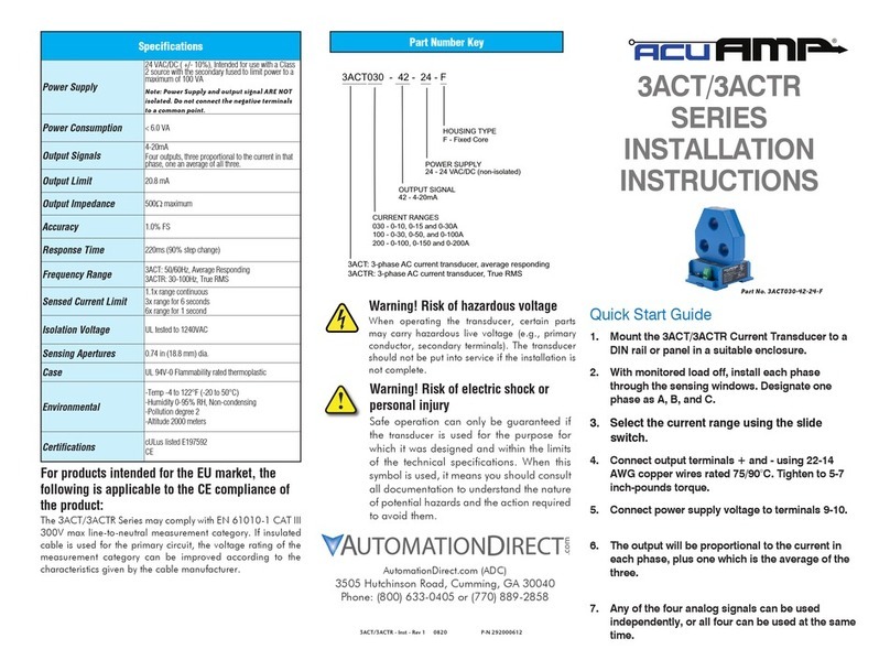
Part Number Key
AutomationDirect.com (ADC)
3505 Hutchinson Road, Cumming, GA 30040
Phone: (800) 633-0405 or (770) 889-2858
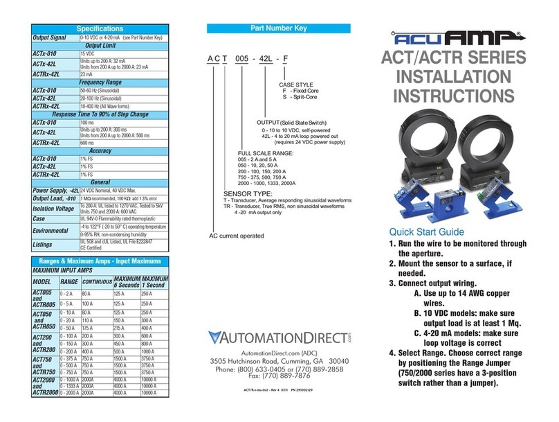
ACT/ACTR
SERIES
INSTALLATION
INSTRUCTIONS
Quick Start Guide
1. Remove top section of sensing ring off by
carefully prying clips away and lifting the
section vertically.
2. Mount the sensor to a DIN rail or surface
using screws in corners, if needed.
3. Place conductor inside ring and replace top
section until the clips snap firmly closed.
4. Connect output wiring.
a. Use No. 22 to 14 AWG copper wires rated
min. 75C and tighten terminals to 5-7 in-lbs.
b. Ensure output load does not exceed
product specifications.
c. Connect 24 VDC power supply and load
in series. Observe polarity.
5. Verify that the display or controller is
reading the output correctly (4mA).
6. Energize the monitored circuit.
ACT 400 - 42L - S
ACT: AC current transducer, average responding
ACTR: AC current transducer, True RMS
CASE STYLE
RANGE
400 A
600 A
800 A
1200 A
S - Split Core
OUTPUT
42L - 4-20mA, loop powered
®
ACT/ACTR - Inst - Rev 1 0820 P-N 292000109
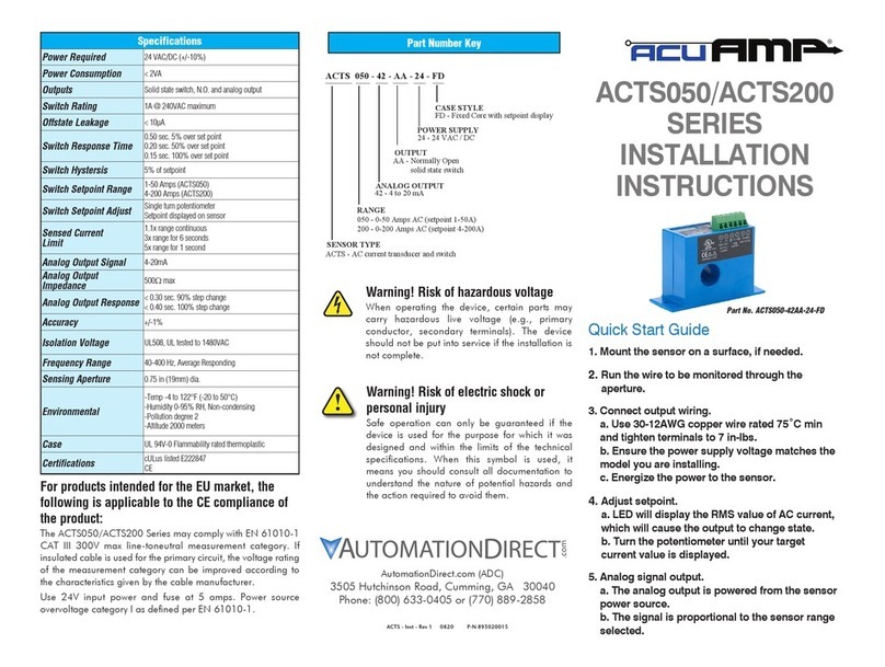
Specifications
Power Supply
24VDC nominal, (12-32VDC)
Intended for use with a Class 2 source with the
secondary fused to limit power to a maximum
of 100 VA
Output Signal 4-20 mA, Loop Powered
Output Limit 23mA
Output Impedance < 600Ω@ 24VDC
Accuracy 1.0% FS, 10 to 100% of range
Frequency Range ACT: 50/60Hz, Average Responding
ACTR: 20-400Hz, True RMS
Isolation Voltage UL tested to 2200VAC
Response Time 600ms (90% step change)
Case UL 94V-0 Flammability rated thermoplastic
Sensing Aperture
2.22 X 1.19 in (56.3 X 30.2 mm)
ACT1200:
3.44 x 2.31 in (87.3 x 58.8 mm)
Environmental
-Temp -4 to 122°F (-20 to 50°C)
-Humidity 0-95% RH, Non-condensing
-Pollution degree 2
-Altitude 2000 meters
Certifications UL/cUL File E197592
CE
Warning! Risk of electric shock or
personal injury
Safe operation can only be guaranteed if the
transducer is used for the purpose for which it was
designed and within the limits of the technical
specifications. When this symbol is used, it
means you should consult all documentation to
understand the nature of potential hazards and
the action required to avoid them.
For products intended for the EU market, the
following is applicable to the CE compliance of
the product:
The ACT/ACTR Series may comply with EN 61010-1 CAT III
300V max line-to-neutral measurement category. If insulated
cable is used for the primary circuit, the voltage rating of the
measurement category can be improved according to the
characteristics given by the cable manufacturer.
Warning! Risk of hazardous voltage
When operating the transducer, certain parts
may carry hazardous live voltage (e.g., primary
conductor, secondary terminals). The transducer
should not be put into service if the installation is
not complete.
Sensed Current Limit
Range Continuous 6 Seconds 1 Second
All 1600A 1920A 6400A
Troubleshooting
1. Sensor has no output.
A. Power supply is not properly sized.
Check power supply voltage and current rating.
B. Polarity is reversed.
Check and correct output wiring polarity.
2. Output signal too low.
A. The range may be too high for current being monitored..
Exercise care when selecting the model range.
B. The load current is not sinusoidal.
Select an ACTR transducer for use with distorted waveforms.
C. Monitored current is below minimum required.
Loop the monitored wire several times through the aperture
until the "sensed" current rises above minimum.
Sensed Amps = (Actual Amps) x (Number of Loops).
Count loops on the inside of the aperture.
3. Sensor is always at 4mA.
Monitored load is not AC or is not on.
Check that the monitored load is AC and that it is actually
on.
4. Output signal is always at 20mA.
The range is too low for current being monitored.
Select a model with a higher range.
Description
The ACT/ACTR Series transducers combine a current
transformer and a signal conditioner into a single package.
This provides higher accuracy, lower wiring costs, easier
installation and saves valuable panel space. Both the ACT
and ACTR are available in a split core housing with a 4-20mA
output proportional to the primary AC current. ACTR series
feature a True RMS output. They are designed for application
on distorted current wave forms such as VFD outputs.
Installation
Place wire or bus bar to be monitored through the sensing
aperture.
The ACT/ACTR series transducers work in the same
environment as motors, contactors, heaters, pull-boxes and
other electrical enclosures. They can be mounted in any
position or hung directly on wires with a wire tie or snapped
directly to a 35mm DIN rail. Just leave at least one inch
distance between sensor and other magnetic devices.
Power Supply
Minimum Power Supply = 12 VDC + Total Loop Voltage
Drop
+
-
-
+
Load
(PLC, meter)
-
24VDC
Power
+
Output Wiring
Connect control or monitoring wires to the sensor. Use up to
22 to 14 AWG rated minimum 75°C copper wire and tighten
terminals to 5-7 in-lbs torque. Be sure the output load does
not exceed 600 ohms with 24VDC power supply.
Connection Notes:
• Captive screw terminals
• 14-22 AWG solid or stranded
• Observe polarity
0 250 500 750
1000
32V
22V
12V
Operating
Range
Total Loop Impedance (Ohms)
LOOP
POWE
R
(VDC)
Intended for use with a Class 2 source with the secondary fused
to limit power to a maximum of 100 VA.
Model Range Select
The ACT/ACTR Series transducers feature factory-calibrated
ranges. This eliminates time-consuming and inaccurate field
setting of zero or span.
1. Determine the normal operating amperage of your
monitored circuit using load specifications or a test
ammeter.
2. Select the model with a range that is equal to or slightly
higher than the normal operating amperage.

This manual suits for next models

1

Other Automationdirect.com Transducer manuals

Automationdirect.com ACT050 User manual

Automationdirect.com

Automationdirect.com ACT050 User manual

Automationdirect.com AcuAmp 3ACT Series User manual

Automationdirect.com

Automationdirect.com AcuAmp 3ACT Series User manual

Automationdirect.com AcuAMP ACTS050 Series User manual

Automationdirect.com

Automationdirect.com AcuAMP ACTS050 Series User manual

Popular Transducer manuals by other brands

S+S Regeltechnik PREMASGARD SHD Operating Instructions, Mounting & Installation

S+S Regeltechnik

S+S Regeltechnik PREMASGARD SHD Operating Instructions, Mounting & Installation

HBM P6A Mounting instructions

HBM

HBM P6A Mounting instructions

Thyracont B VSP63D Assembling instructions

Thyracont

Thyracont B VSP63D Assembling instructions

Nexus NX Wireless Wind Transducer set Installation and operation manual

Nexus

Nexus NX Wireless Wind Transducer set Installation and operation manual

SIAP+MICROS t027 TP200 User manual and maintenance

SIAP+MICROS

SIAP+MICROS t027 TP200 User manual and maintenance

Balluff BTL7-V50D-M P-C003 Series user guide

Balluff

Balluff BTL7-V50D-M P-C003 Series user guide

WHD Exciter X.25-4 quick start guide

WHD

WHD Exciter X.25-4 quick start guide

M-system 18PV instruction manual

M-system

M-system 18PV instruction manual

HBM S9M Mounting instructions

HBM

HBM S9M Mounting instructions

Simrad TRANSDUCER - INSTALLATION GENERIC REV H installation manual

Simrad

Simrad TRANSDUCER - INSTALLATION GENERIC REV H installation manual

HBM SK12 Mounting instructions

HBM

HBM SK12 Mounting instructions

TSI Incorporated 8455 Operation and service manual

TSI Incorporated

TSI Incorporated 8455 Operation and service manual

Mianyang Weibo Electronic WBV414U05 user manual

Mianyang Weibo Electronic

Mianyang Weibo Electronic WBV414U05 user manual

Ashcroft A2X instruction sheet

Ashcroft

Ashcroft A2X instruction sheet

Fairchild T6000 instructions

Fairchild

Fairchild T6000 instructions

Gossen MetraWatt SINEAX DME 4 Series operating instructions

Gossen MetraWatt

Gossen MetraWatt SINEAX DME 4 Series operating instructions

Ametek 742R Operation, maintenance, and installation instructions

Ametek

Ametek 742R Operation, maintenance, and installation instructions

Iskra iMT416 user manual

Iskra

Iskra iMT416 user manual

manuals.online logo
manuals.online logoBrands
  • About & Mission
  • Contact us
  • Privacy Policy
  • Terms and Conditions

Copyright 2025 Manuals.Online. All Rights Reserved.