manuals.online logo
Brands
  1. Home
  2. •
  3. Brands
  4. •
  5. novotechnik
  6. •
  7. Transducer
  8. •
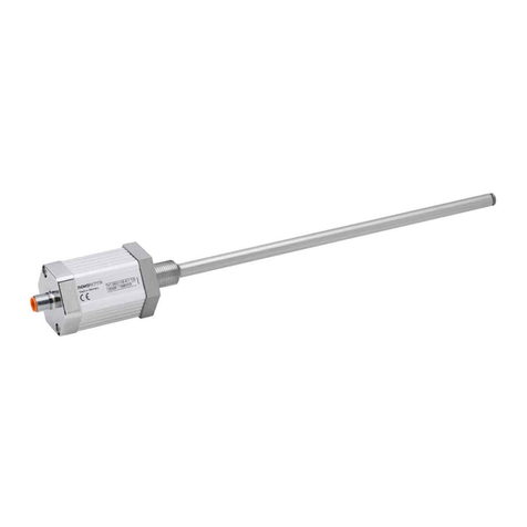
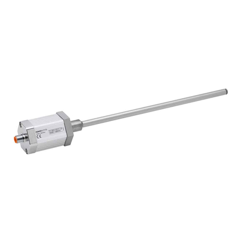
  9. novotechnik LWG Series User manual

novotechnik LWG Series User manual

LWG/LWX Gebrauchsanleitung
LWG/LWX Manual
Artikelnummer / Item number: 515533/09 Änderungen vorbehalten / Subject to change without notice 2012/07
1
Allgemeine Beschreibung
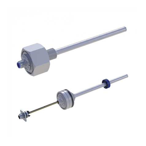
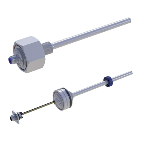
Die Baureihe LWG/LWX ist ein potentiometrischer
Wegaufnehmer für die direkte, genaue und absolute
Messung von Wegen bzw. Längen in der Steuerungs-,
Regelungs- und Messtechnik.
2
Sicherheitshinweise
Unsere Produkte sind regelmäßig nicht für Luft- und
Raumfahrtanwendungen zugelassen und dürfen nicht in
kerntechnischen oder militärischen, insbesondere ABC-
relevanten Applikationen verwendet werden.
Weitere Informationen s. unsere AGBs.
2.1 Bestimmungsgemäße Verwendung
Der Wegaufnehmer LWG/LWX wird zu seiner
Verwendung in eine Maschine oder Anlage eingebaut.
Er bildet zusammen mit einer Steuerung (z.B. SPS) ein
Wegmesssystem und darf auch nur für diese Aufgabe
eingesetzt werden.
Unbefugte Eingriffe, nicht bestimmungsgemäße
Verwendung oder Nichtbeachtung der Montagehinweise
führen zum Verlust von Gewährleistungs-, Garantie- und
Haftungsansprüchen.
2.2 Installation & Inbetriebnahme
Der Wegaufnehmer ist nur von Fachpersonal und unter
Berücksichtigung aller geltenden Sicherheits-
bestimmungen in Betrieb zu nehmen.
Alle Maßnahmen zum Schutz von Personen und Sachen
bei einem Defekt des Wegaufnehmers müssen vor der
Inbetriebnahme getroffen werden.
Schubstange und Druckausgleichsventil nicht einfetten!
3
Elektrischer Anschluss
Die Versorgungsspannung darf nur ausschließlich an die
dafür vorgesehenen Anschlüsse verbunden werden. Die
Abschirmung des Anschlusskabels ist an Masse
anzuschließen. Falsche Verbindungen und Überspannung
können zur Beschädigung der Bauteile führen. Prüfen Sie
deshalb vor dem Einschalten die Anschlüsse immer
sorgfältig.
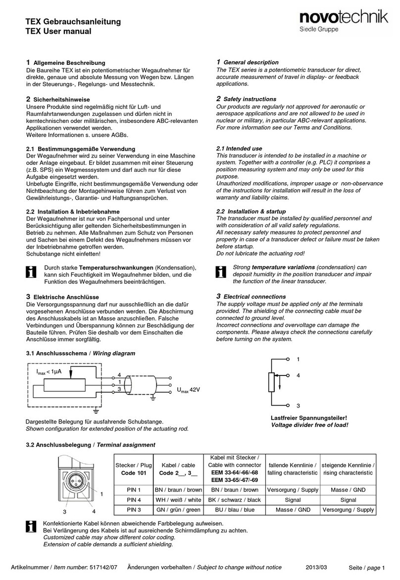
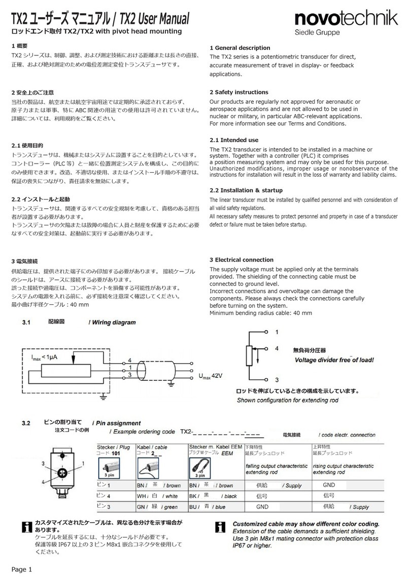
3.1 Anschlussschema / Wiring diagram
1
General description
The LWG/LWX series is a potentiometric transducers for
direct, accurate measurement of travel in display- or
feedback applications.
2
Safety instructions
Our products are regularly not approved for aeronautic or
aerospace applications and are not allowed to be used in
nuclear or military, in particular ABC-relevant applications.
For more information see our Terms and Conditions.
2.1 Intended use
This transducer is intended to be installed in a machine or
system. Together with a controller (e.g. PLC) it comprises
a position measuring system and may only be used for
this purpose.
Unauthorized modifications, improper usage or non-
observance of the instructions for installation will result in
the loss of warranty and liability claims.
2.2 Installation & startup
The transducer must be installed by qualified personnel
and with consideration of all valid safety regulations.
All personal and property protection measures in case of
a transducer defect or failure must be taken before startup.
Do not lubricate the actuating rod and the pressure
compensating valve!
3
Electrical connections
The supply voltage must be applied only at the terminals
provided. The shielding of the connecting cable must be
connected to ground level.
Incorrect connections and overvoltage can damage the
components. Please always check the connections
carefully before turning on the system.
2
1
3
4
U
max
42V
I
max
< 1µA
2
1
3
4
U
max
42V
I
max
< 1µA
3.2 Anschlussbelegung / Terminal assignment
(Sicht auf den Flanschstecker / front view to the flange connector )
4
2
3
1
3
2
1
PIN 4 nicht belegt
PIN 4 not connected
Lastfreier Spannungsteiler!
Voltage divider free of load!
Seite / page 1
Stecker / Plug Kabel / cable
Code 201
fallende Kennlinie /
falling characteristic
steigende Kennlinie /
rising characteristic
PIN 1 BN / braun / brown Versorgung / Supply Masse / GND
PIN 2 BK / schwarz / black Signal Signal
PIN 3 RD / rot / red Masse / GND Versorgung / Supply
PIN 4 nicht anschließen / do not connect
Dargestellte Belegung für ausfahrende Schubstange / Displayed schematic for extending rod.
LWG/LWX Gebrauchsanleitung
LWG/LWX Manual
Artikelnummer / Item number: 515533/09 Änderungen vorbehalten / Subject to change without notice 2012/07
4
Ausführungen / Versions
4.1 Steckerverbindung / Plug connection
Im Lieferumfang enthalten: 1x 4-pol. Steckverbindung M12 x 1
Included in delivery: 1x 4-pin round connector M12 x 1
LWG-0___
LWX-0___-001
LWX-0___-002
Schutzrohr / protective tube
empfohlener Einbau
horizontal: Stecker nach unten
vertikal: Schubstange nach unten
recommended mounting
horizontal: plug down
vertical: actuating rod down
Druckausgleichsventil /
pressure compensating valve
Druckausgleichsventil /
pressure compensating valve
Seite / page 2
Konfektionierte Kabel können abweichende
Farbbelegung aufweisen.
Bei Verlängerung des Kabels ist auf ausreichende
Schirmdämpfung zu achten.
Customized cable may show different color coding.
Extension of cable demands a sufficient shielding.
LWG-0___-003 (kundenspezifisch / customized)
4.2 Kabelverbindung / Cable connection
LWG-0___-000-201
LWX-0___-001-201
LWX-0___-002-201
40 -50 Ncm
Bei Nachjustierung, Gelenkkopf mit
max. 4 Nm anziehen!
By readjustment, the pivot head
has to be tightened with max. 4 Nm!
Befestigungsschraube / fastening screw M3
(dem Messsystemkabel beigelegt / supplied with measuring system cable)
Wegmesssystemkabel /
Measuring system cable
4-pol. Stecker /
4-pin plug
Flachdichtung / Flat seal
(dem Messsystemkabel beigelegt / supplied with measuring system cable)
Montagehinweis zum kundenspezifischen
Wegmesssystem:
Zur Gewährleistung elektromagnetischer Verträglichkeit
(EMV) muss das mitgelieferte Masseband zwischen
dem Wegmesssystem und dem Controller
angeschlossen werden. Der Controller muss ebenfalls
am Geräteseitigen Erdungspunkt angeschlossen
werden.
Instruction for installation to the customized position
transducer:
In order to guarantee electromagnetic compatibility
(EMC) the supplied ground band must be connected
between the measuring system and the controller. The
controller must also be connected to the device-sided
ground point.
Anschluss für Massekabel /
Connection for ground cable

This manual suits for next models

4

Other novotechnik Transducer manuals

novotechnik TH1 Series User manual

novotechnik

novotechnik TH1 Series User manual

novotechnik TIM Series User manual

novotechnik

novotechnik TIM Series User manual

novotechnik TM1 Series User manual

novotechnik

novotechnik TM1 Series User manual

novotechnik RSM-2800 User manual

novotechnik

novotechnik RSM-2800 User manual

novotechnik TEX Series User manual

novotechnik

novotechnik TEX Series User manual

novotechnik TM1 Series User manual

novotechnik

novotechnik TM1 Series User manual

novotechnik RFC-4800 CAN User manual

novotechnik

novotechnik RFC-4800 CAN User manual

novotechnik TX2 Series User manual

novotechnik

novotechnik TX2 Series User manual

novotechnik T Series User manual

novotechnik

novotechnik T Series User manual

novotechnik LWX Series User manual

novotechnik

novotechnik LWX Series User manual

novotechnik LS1 Series User manual

novotechnik

novotechnik LS1 Series User manual

novotechnik TMI Series User manual

novotechnik

novotechnik TMI Series User manual

novotechnik RSM-2800 User manual

novotechnik

novotechnik RSM-2800 User manual

novotechnik TLM 102 Series User manual

novotechnik

novotechnik TLM 102 Series User manual

novotechnik TH1 CANopen User manual

novotechnik

novotechnik TH1 CANopen User manual

novotechnik Z-TF1-PO1 User manual

novotechnik

novotechnik Z-TF1-PO1 User manual

novotechnik TIM Series User manual

novotechnik

novotechnik TIM Series User manual

novotechnik RSC-2800 User manual

novotechnik

novotechnik RSC-2800 User manual

novotechnik TLH User manual

novotechnik

novotechnik TLH User manual

novotechnik TH1 Series User manual

novotechnik

novotechnik TH1 Series User manual

novotechnik PTP Series User manual

novotechnik

novotechnik PTP Series User manual

novotechnik TP1 Series User manual

novotechnik

novotechnik TP1 Series User manual

Popular Transducer manuals by other brands

Seneca T201DC100 Installation and user guide

Seneca

Seneca T201DC100 Installation and user guide

H2O Marine SonicShield P20-100-12 Volt installation guide

H2O

H2O Marine SonicShield P20-100-12 Volt installation guide

Veris PX3 Series installation guide

Veris

Veris PX3 Series installation guide

Sonic immersion iBeam VT300 install guide

Sonic immersion

Sonic immersion iBeam VT300 install guide

KEPO DAP9050-E5 manual

KEPO

KEPO DAP9050-E5 manual

SSD ranger 5575 product manual

SSD

SSD ranger 5575 product manual

Setra Systems GCT225 installation guide

Setra Systems

Setra Systems GCT225 installation guide

halstrup-walcher PS 18 instruction manual

halstrup-walcher

halstrup-walcher PS 18 instruction manual

Airmar Tilted Element B164 Owner's guide and installation instructions

Airmar

Airmar Tilted Element B164 Owner's guide and installation instructions

Maxcess IPT-E instruction manual

Maxcess

Maxcess IPT-E instruction manual

Beck 982R Series manual

Beck

Beck 982R Series manual

Mastech CT300 Operator's manual

Mastech

Mastech CT300 Operator's manual

Balluff BTL7-A M Series user guide

Balluff

Balluff BTL7-A M Series user guide

Humminbird XNT 9 DB 74 T installation guide

Humminbird

Humminbird XNT 9 DB 74 T installation guide

Balluff BTL6-V11V-M Series user guide

Balluff

Balluff BTL6-V11V-M Series user guide

Nexus Compass 35 Installation and operation manual

Nexus

Nexus Compass 35 Installation and operation manual

Simrad ES120-7C -  REV D datasheet

Simrad

Simrad ES120-7C - REV D datasheet

GP:50 216/316 installation manual

GP:50

GP:50 216/316 installation manual

manuals.online logo
manuals.online logoBrands
  • About & Mission
  • Contact us
  • Privacy Policy
  • Terms and Conditions

Copyright 2025 Manuals.Online. All Rights Reserved.