AutoTest AutoStop Mini Plus User manual

User Manual
Version 2.014
AutoStop
Mini Plus

N17561
DECLARATION OF CONFORMITY
We, AutoTest products Pty Ltd. declare under our sole responsibility that the product Mini
Plus is in conformity with the provisions of the following Council Directive: 1999/5/EC.
A copy of the Declaration of Conformity is available from http://www.autotest.net.au
© AutoTest Products Pty Ltd (AutoTest) [2015].
Copyright in the drawings, information and data recorded in this document (the
information) is the property of AutoTest Products. This document and the information are
solely for the use of the authorised recipient and this document may not be used, copied,
or reproduced in whole or part for any purpose other than that for which it was supplied
by Auto Test Products. Auto Test Products makes no representation, undertakes no duty,
and accepts no responsibility to any third party who may use or rely upon this document
or the information.
Under no circumstances shall Auto Test Products be responsible for any loss of data or
income or any special, incidental, consequential or indirect damages howsoever caused.
The contents of this document are provided "as is". Except as required by applicable law,
no warranties of any kind, either express or implied, including, but not limited to, the
implied warranties of merchantability and fitness for a particular purpose, are made in
relation to the accuracy, reliability of
contents of this document. Auto Test Products reserves the right to revise this document
or withdraw it at any time
without prior notice.
Please dispose of batteries properly.

AutoStop Mini Plus User Manual v2.014 Page 1
Table of Contents
AutoStopTM Mini Plus
1UNPACKING AND FIRST TIME USE ....................................................................2
1.1 Unit activation .......................................................................................................2
1.2 Self Test and Battery Check.................................................................................2
2FOR YOUR SAFETY..............................................................................................3
3OPERATION...........................................................................................................4
3.1 Test Conditions and Test Area ............................................................................4
3.2 Set-Up in Vehicle...................................................................................................4
3.3 Changing the units................................................................................................4
3.4 Running the Test...................................................................................................5
3.5 Test Instructions Summary..................................................................................6
3.6 Other Functions ....................................................................................................7
3.7 Printing on Bluetooth printer (optional accessory) ...........................................7
3.8 Menu Reference ....................................................................................................8
4DOWNLOADING..................................................................................................12
4.1 Systems Requirements ......................................................................................12
4.2 Installing the Data Logger Software From CD..................................................12
4.3 Installing the Data Logger Software From Internet..........................................12
4.4 Downloading Tests using the Data Logger Software ......................................12
4.4.1 Downloading via USB..................................................................................13
4.4.2 Downloading via Bluetooth.........................................................................21
4.5 Using the Data Logger software........................................................................26
5SPECIFICATION ..................................................................................................28
5.1 Hardware Specifications ....................................................................................28
5.2 Features...............................................................................................................28
6CALIBRATION PROCEDURE..............................................................................29
6.1 Return of AutoStop Mini Plus for Calibration...................................................29
6.1.1 Packaging.....................................................................................................29
6.1.2 Shipping........................................................................................................29
6.1.3 Documentation.............................................................................................29
7TROUBLESHOOTING..........................................................................................29
8WARRANTY.........................................................................................................30
9AUTHORISED SERVICE AGENTS:.....................................................................31

AutoStop Mini Plus User Manual v2.014 Page 2
1 UNPACKING AND FIRST TIME USE
Congratulations on your choice of an AutoStop Mini Plus. Please take the time to read
this User’s Manual before using the AutoStop Mini Plus in the field. Incorrect or
inappropriate use of this instrument may void the warranty. Retain the packing materials
for future shipping and transport of the unit for calibration every two years.
Please complete the warranty registration card and post it to AutoTest Products Pty Ltd,
alternatively visit our website www.autotest.net.au and complete your warranty
registration on line. Your warranty registration ensures that you are kept up-to-date on
any software or hardware changes to your AutoStop Mini Plus.
The packing box of your AutoStop Mini Plus should contain the following:
1. AutoStop Mini Plus
2. User Manual
3. Warranty Registration Card
4. Calibration Certificate
5. Power Adaptor
Optional Accessories:
MiniPlus Data logger software CD-ROM
Data Download USB cable
Bluetooth Wireless printer
Rare Earth magnet motorbike kit
AutoStop Mini Plus determines triaxial deceleration, measuring forward as well as
sideways deceleration (lane change). AutoStop Mini Plus has a twelve-button operation
via a tactile membrane keypad with LCD display. It is lightweight (500grms) and compact
(200x70x40mm) and can be installed anywhere in the vehicle.
1.1 Unit activation
When you receive your new Meter, you must activate it before you can use it. When you
turn it on for the first time, you will come to the main menu. The first option on the menu
will be “Activate”.
Press the ENTER key to begin activation. You are now prompted to enter the 5-digit
serial number, one digit at a time. Press ENTER to confirm, DEL to re-enter.
Once your meter is activated, it is ready for use, and you will never need to perform the
activation again.
1.2 Self Test and Battery Check
The self-test function is activated each time the AUTOSTOP™ Mini Plus is powered, it
checks the clock, the battery level and the calibration due date. The sequence as follows:
- after initial power up and start-up splash screen sequence the display will indicate
“Test?” If the battery does not have sufficient charge to be used, then it will display
“Warning: Battery Low”.

AutoStop Mini Plus User Manual v2.014 Page 3
2 FOR YOUR SAFETY
Read these simple guidelines. Not following them may be dangerous. Read the
complete user guide. Further detailed information is given in this manual.
SWITCH ON SAFELY
Do not switch the device on when wireless device use is prohibited or when it may
cause interference or danger.
INTERFERENCE
All wireless devices may be susceptible to interference, which could affect
performance.
SWITCH OFF WHEN REFUELING
Do not use the device at a refuelling point. Do not use near fuel or chemicals.
SWITCH OFF NEAR BLASTING
Follow any restrictions. Do not use the device where blasting is in progress.
USE SENSIBLY
Use only in the positions as explained in the product documentation.
QUALIFIED SERVICE
Only qualified personnel may install or repair this product.
ACCESSORIES AND BATTERIES
Use only approved accessories and batteries. Do not connect incompatible
products.
WATER-RESISTANCE
Your device is not water-resistant. Keep it dry.
CONNECTING TO OTHER DEVICES
When connecting to any other device, read its user's guide for detailed safety
instructions. Do not connect incompatible products.

AutoStop Mini Plus User Manual v2.014 Page 4
3 OPERATION
3.1 Test Conditions and Test Area
The vehicle must be stationary (at a complete stop) prior to commencement of the test.
Ideal conditions are to test the vehicle at a location where no other or only few vehicles
are present. However, if it is necessary to use another area, such as a public road, only
commence the test if there is no danger of an accident. The test area should be a sealed,
flat bitumen road. The headwind should be less than 15km/h.
Test starts with first movement of the vehicle, and concludes when the vehicle comes to
a complete stop. The forward direction of the vehicle is determined when the vehicle first
starts to move. For example, if the test is started when the vehicle pulls out from the kerb,
then the calculated forward direction will be at an angle to the true forward direction. The
first movement of the vehicle must be in the forward direction. Please be sure to follow
the brake test procedure detailed in the latest version of the relevant Inspection Manual
when carrying out a statutory test.
3.2 Set-Up in Vehicle
Attach the Mini Plus to the dashboard, front passenger seat, foot well or centre console
so that the screen is clearly visible and the buttons are accessible. AutoStop Mini Plus is
self-aligning by identifying its orientation during acceleration at the beginning of each test
- Mini Plus can be installed at any angle facing any orientation, but must be secure for
the entire duration of the test as movement can cause wrong deceleration readings.
Note: If Mini Plus is configured for use in heavy vehicles, it should only be mounted flat
on a levelled surface, or on the side-window of the vehicle using suction cup mounts. In
such cases, if the tilt angle of the device is outside the tolerance level, the device will
display “Slope too large”. The tilt warning message will disappear automatically once the
slope angle of the unit is adjusted to the level plane (in reference to ground).
3.3Changing the units
The resultant average deceleration and max deceleration can be viewed in different units
like g, m/s2or %. The speed, stopping distance and the side shift can be viewed can be
in imperial and metric units. To select the units, press ON/OFF button to power up the
unit. The display will show “Test?” press →until it displays “Set Accel. Unit?” to
change the units of average and maximum deceleration. There are three options for
acceleration units: m/s2, g or %. Press →to select a unit and ENTER to set a unit.
Acceleration Units
m/s2
g
% (where 0% = 0.00g, 100% = 1.00g)
The units of speed, stopping distance and side shift can be changed to imperial or metric.
Select Imperial/Metric? option from the main menu. Press ENTER. Select imperial or
metric units and press ENTER. The speed, stopping distance and side shift in both units
are as follows:
Unit
Imperial
Metric
Speed
Miles per hour (mph)
Kilometres per hour (km/h)
Stopping distance
Feet (ft)
Meter (m)

AutoStop Mini Plus User Manual v2.014 Page 5
3.4 Running the Test
Turn on AutoStop Mini Plus by pressing ON/OFF. The Mini Plus will go through a start-up
procedure and show the calibration due date. The display will show “Test?” press
‘ENTER’. The Mini Plus will initialise the test procedure by prompting the user to enter
“Examiner ID”, “Customer Name” and “Vehicle Registration No.” The Mini Plus will
remember the previously stored Examiner ID. To change the Examiner ID, press → then
key-in the new ID. Once the vehicle registration number has been entered, the Mini Plus
will then prompt the user select the vehicle category. The vehicle category can either be
“Light Vehicle” (VEHICULE LEGER) or “Heavy Vehicle” (VEHICULE LOURD). Once the
vehicle category has been selected, the Mini Plus will prompt the user to specify the
vehicle type. The vehicle-type is selected from the following tables depending on the
previously selected vehicle category.
Vehicle types for Light Vehicles
(VEHICULE LEGER)
Type
Limit value (m/s2)
VP > 01/10/1989
5.0
VUL > 01/10/1989
5.0
1956 < VP < 1989
5.0
1956 <VUL < 1989
4.5
VP < 31/12/1955
3.5
VUL < 31/12/1955
3.0
Vehicle types for Heavy Vehicles
(VEHICULE LOURD)
Type
Limit value (m/s2)
M1 >3,5t
5.0
M2,M3 avec ABR
5.0
M2,M3 sans ABR
4.8
N1 > 29/09/1989
5.0
N1 < 30/09/1989
4.5
N2,N3 > 01/01/12
5.0
1989<N2,N3< 2012
4.5
N2,N3 < 30/09/89
4.3
Ensemble routier
4.3
Press the (→) and DEL keys to scroll through the list of vehicle types.When a particular
vehicle type is displayed on the screen, press the ENTER key to select it and continue to
the next step. The Mini Plus will then show “Press any key to commence the test”.
After pressing any key, the display will show “Ready to go”. Drive the vehicle to the
desired test speed and apply the brakes. When the vehicle has come to a halt the Mini
Plus will finish the calculations and will display the results –you can then simply compare
them with the specific brake values according to your local regulations. The results that
will be displayed are:

AutoStop Mini Plus User Manual v2.014 Page 6
1. Average Deceleration (SRV36)
2. Maximum Deceleration
3. Test Duration
4. Pass/Fail Outcome
The pass/fail outcome of the test will be determined based on the type of the vehicle
selected and the measured value of the average deceleration (SRV36). If the measured
average deceleration (SRV36) is below the limit value, the test outcome will be ‘Fail’
(INSUFFISANTE). Otherwise, the test outcome will be ‘Pass’ (OK) when the measured
SRV36 value is above or equal to the limit value.
3.5 Test Instructions Summary
Screen Display
Instruction
Keys to Press
Blank Screen
Switch On
ON/OFF
Initial splash screen
Press any key to skip
Test?
Start to run test
ENTER
Examiner?
Enter Examiner ID if it is not
stored previously
Press key and key-in ID
and press ENTER
Customer:
Enter customer name
Key-in customer name and
press ENTER
Reg No:
Enter the Registration no
Key-in registration no and
press ENTER
Test with GPS?
Conduct test with GPS
Press ENTER for YES and
any other key for NO
Press any key to
commence the test
Press any key to commence
the test
Press any key to commence
the test
Ready to go…
Accelerate the vehicle
Prelude…
Forward direction detected.
Keep accelerating to
desired speed, then brake
Sampling…
Wait for result
Calculating…
Wait for result
Avg Decel (SRV36), Max
Decel, duration, pass/fail
Displays the test results of
brake test
Press ENTER
Save?
To save test result
Press ENTER to save or →
to go to next item
Print?
To print test result on
remote Bluetooth printer
Press ENTER to print or →
to go to next item
Print Another?
To print duplicate test result
Press ENTER if you want to
print the test result or press
→
Repeat Test?
To repeat same test
Press ENTER to repeat the
test or →to go to main
menu.
Must:
–Fix Mini Plus securely
–Install in a stationary vehicle
–Must drive in a straight line

AutoStop Mini Plus User Manual v2.014 Page 7
Must not:
–Turn car after starting test
–Hold unit in hand or on body
–Move Mini Plus after pressing start
–Skid wheels
“A good stop is like stopping at a traffic light –steady.”
3.6 Other Functions
View Results? : Press ENTER and display will show the test number and the
date and time of test. Press →to select the required test number and press
ENTER to view each test result. Mini Plus can store up to ninety test results. At
the end there is a “Clear Results?” option to clear all test results. The Mini Plus
will hold ninety tests and will display “Memory full” when the memory is full and
stored data has to be cleared.
Adjust Contrast? : Press ENTER to adjust the contrast of the display and press
→to increase the contrast and DEL to reduce contrast.
Set acceleration units? : Press ENTER to select acceleration unit. The
acceleration units can be changed to g, percentage or m/s2
Imperial/Metric? : Press ENTER to change to Imperial or Metric units.
View Clock? : This function is for viewing the date and time set on Mini Plus.
Press ENTER to view the clock
Battery Life? : Press ENTER to view the battery life of the Mini Plus
View Accel? : This function is to view the X, Y and Z-axes of the accelerometer.
Press ENTER to view these values.
View Test Count? : This function is to view the total number of tests carried on
the Mini Plus after calibration. Press ENTER to view the test count.
Language? : This function allows users to select a different interface language.
Press ENTER to view available languages. Note: results obtained using French
language will be based on SRV-P036 standard.
3.7 Printing on Bluetooth printer (optional accessory)
In order to print the test results on Bluetooth printer, switch on the printer and give print
command from the Mini Plus. Mini Plus will display “Finding printer” while searching for
the Bluetooth printer. Once the Bluetooth printer is found, Mini Plus will automatically
issue the printout of the test via the Bluetooth printer.
Note: When Mini Plus is not able to find a Bluetooth printer it will display “No printer
found” and "Find printer? Y/N" messages on the LCD screen. Switch OFF the Bluetooth
printer and switch it back ON and select “Find printer? Y” from Mini Plus to retry printing.

AutoStop Mini Plus User Manual v2.014 Page 8
3.8 Menu Reference
Display Main
Menu
Display Sub Menu
Description
Keys to Press
Activate Unit?
This to activate the
MiniPlus as the unit is
locked prior to
shipment
Press ENTER or
→to view next
item on main menu
Please enter the 5-
digit Serial Number
code of this unit,
then press ENTER to
confirm, or DEL to
re-enter. Press any
key to begin
Press any key to
go to next sub-
menu
Code: -----
This is to enter the 5-
digit serial number
code
Key-in the 5-digit
serial number and
Press ENTER
Unit Activated
This is an indication
that the unit has been
activated
Press ENTER
Test?
This does not appear if
unit is not activated.
This is for carrying out
the test
Press ENTER
Examiner?
This is for enter the
name of the person
carrying out the test.
Press →, when
cursor appears
key-in the examiner
name
Customer:
This is for entering the
name of the customer
Key-in the
customer name
and Press ENTER
Reg No:
This is for entering the
registration number of
the vehicle under test
Key in the
registration number
and press ENTER
Test with GPS?
This is to decide
whether or not the test
require GPS location
Press ENTER for
YES and any other
key for NO
Press any key to
commence test.
This is an indication to
press any key to
commence the test
Press any key
Stabilising…
This is when the unit is
checking its stability
Ready to go…
Accelerate the vehicle
to the desired speed
Prelude…
This indicates forward
motion of the test
vehicle.

AutoStop Mini Plus User Manual v2.014 Page 9
Sampling…
This indicates that the
brakes have been
applied and it is
sampling data for
calculation
Calculating…
This indicates that the
test is complete and
the unit is calculating
the results
The test results are
displayed in a scrolling
text showing the
#AvgDecel,
MaxDecel, Duration,
Pass/Fail
Save?
This is for saving the
current test result
Press ENTER to
save or →to go to
next sub menu
Print?
This is for printing the
test result via
Bluetooth printer
(optional accessory)
Press ENTER to
print or →to go to
next sub menu
Print Another?
This option is to print
another copy of the
same test
Press ENTER to
print or →to go to
next sub menu
Repeat Test?
This is for repeating
test
Press ENTER
View Results?
This is for viewing the
stored data
Press ENTER to
view results or →to
go to next sub
menu
3/n
This is third (last)
result out of nstored
results
Press ENTER to
view results of the
second test or
Press →to go to
next sub menu
2/n
This is second result
out of nstored results
Press ENTER to
view results of the
second test or
Press →to go to
next sub menu
1/n
This is first result out
of nstored results
Press ENTER to
view results of the
second test or
Press →to go to
next sub menu
Clear Results?
This is to clear the
results stored on Mini
Plus
Press ENTER to
clear stores data or
press →to go
back to the main
menu

AutoStop Mini Plus User Manual v2.014 Page 10
Are you sure? Y/N
This is a confirmation
for clearing the results
stored on Mini Plus
Use → to select
Yes/No, then
press ENTER
Set Accel. Unit?
This is to set the units
of average and
maximum deceleration
Press ENTER to
set the acceleration
unit or →to go to
next main menu
Accel unit: m/s2
This is to set the units
of average and
maximum deceleration
in terms of ‘m/s2’
Press ENTER to
set or →to select
another unit
Accel unit: g
This is to set the units
of average and
maximum deceleration
in terms of ‘g’
Press ENTER to
set or →to select
another unit
Accel unit: %
This is to set the units
of average and
maximum deceleration
in terms of ‘%’
Press ENTER to
set or →to select
another unit
Imperial/Metric?
This is to change the
units of speed,
stopping distance and
side shift
Press ENTER to
set the units or
→to go to main
menu
I/M: Metric
This is to change the
units of speed,
stopping distance and
side shift to metric
Press ENTER to
set the unit to
metric or press →
to select another
unit
I/M: Imperial
This is to change the
units of speed,
stopping distance and
side shift to imperial
Press ENTER to
set the unit to
imperial or press
→to select another
unit
View Clock?
This is to view the date
and time on the Mini
Plus
Press ENTER to
set the units or
→to go to main
menu
Date: dd/mm/yy
This shows the date
on the Mini Plus
Wait until display
shows time or
Press →to view
time or Press
ENTER to go to
main menu
Time: hh:mm:ss
This shows the time on
the Mini Plus
Note: press ‘1’ to toggle
daylight saving. When
daylight saving is enabled,
‘*’ will be displayed on
LCD.
Wait until the
display shows date
or Press →to view
date or Press
ENTER to go to
main menu

AutoStop Mini Plus User Manual v2.014 Page 11
Battery Life?
This shows the battery
life on Mini Plus
Press ENTER to
view battery life or
press →to return
to main menu
View Accel. ?
This is to view X, Y
and Z-axes of the
accelerometer
Press ENTER to
view acceleration
or press →to
return to main
menu
Vsum :
This shows the vector
sum of all three axes.
Press →to view
another axis or
press ENTER to go
to main menu
X:
This shows the X-axis
of the accelerometer
Press →to view
another axis or
press ENTER to go
to main menu
Y:
This shows the Y-axis
of the accelerometer
Press →to view
another axis or
press ENTER to go
to main menu
Z:
This shows the Z-axis
of the accelerometer
Press →to view
another axis or
press ENTER to go
to main menu
Tilt :
This shows the tilt
angle of the brake
meter
Press →to switch
to another screen
or press ENTER to
go to main menu
View Test
Count?
This is to view the total
number of tests carried
out on the Mini Plus
Press ENTER to
view the count or
→to go to main
menu
Printer Type?
Allows user to
configure printer
settings
Press ENTER to
open menu
Bluetooth: YES
To enable or disable
Bluetooth printer
Note: If Bluetooth printer
is disabled, the printing
will occur via RS232.
Press → to toggle
between “YES” and
“NO”, press
ENTER to save
settings and return.
Language?
This allows users to
change the unit
interface language.
Press ENTER to
view available
languages

AutoStop Mini Plus User Manual v2.014 Page 12
English ?
Changes interface
language to English
Press ENTER to
select English
language or →to
see the next
language
French ?
Changes interface
language to French.
Note: Results obtained
using French language
will be based on SRV-
P036 standard.
Press ENTER to
select French
language or →to
see the next
language
4 DOWNLOADING
The AUTOSTOP™ Mini Plus can hold 100 tests numbered one to hundred. Test results
stored in Mini Plus can be downloaded to a PC using a USB cable, or via Bluetooth
interface. To download the tests, a datalogger software needs to installed on the PC. The
datalogger software can be installed from the provided CD or can be downloaded from
the Internet.
4.1Systems Requirements
To use the datalogger software, the PC must meet the following requirements:
Operating System: Windows 2000 or later
Disk Space: 10 MB of free hard disk space
4.2 Installing the Data Logger Software From CD
To install the datalogger software from the provided CD, perform the following steps:
1. Insert the Mini Plus Data logger Software CD into your disk drive.
2. Go to My Computer and select your CD-Rom drive (usually D:\ or E:\)
3. Select installation file “setup.exe” and run it.
4. Follow Setup prompts. Make sure you run the application with administrator
level privileges.
4.3Installing the Data Logger Software From Internet
The latest version of the AUTOSTOP™ Mini Plus datalogger software can be freely
obtained from the Internet by opening the following URL:
http://autotest.net.au/ (Select ‘All products’ then select AutoStop Mini Plus)
When the above link opens, select ‘Datalogger Software’ link under ‘Downloads’. Then
simply download and run the installation file.
4.4Downloading Tests using the Data Logger Software
There are a couple of ways of downloading data from Mini Plus. The data can be
downloaded via USB or Bluetooth. Once the datalogger software has been installed, run
the software and follow the downloading instructions given below.

AutoStop Mini Plus User Manual v2.014 Page 13
4.4.1 Downloading via USB
Once the Data Logger software is installed, run the Data Logger software and connect
the Brake Meter to the PC via the supplied USB cable.
Once the USB cable is connected to the PC, switch ON the Brake Meter by pressing the
ON/OFF key. When the Brake Meter is switched ON, the PC will recognise the Brake
Meter device and will search for the USB drivers.
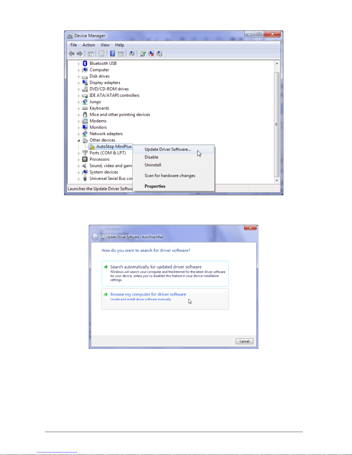
Open device manage to install the USB drivers. The device manager can be accessed by
typing ‘devmgmt.msc’ in the Run Window. The Run Window can be accessed by
pressing + R from the keyboard. Make sure you have administrator level privileges
when accessing Device Manager.
Select ‘AutoStop MiniPlus’in the device manager (under Other devices) and right click on
it. Select “Update driver/software”.
USB
AutoStop Mini Plus User Manual v2.014 Page 14
Select “Browse my computer for driver software” to specify the location where the drivers
are located.
When the browse window is shown, select the USB driver folder located in the directory
where the AutoStop Mini+ datalogger software is installed. On a 64-bit operating system,
the default location where USB drivers are likely to be found is at “C:\Program Files
(x86)\AutoTest\AutoStop Mini+ Data Logger\USB Drivers”. On a 32-bit system, the USB
driver’s folder would be at “C:\Program Files\AutoTest\AutoStop Mini+ Data Logger\USB
Drivers”.

AutoStop Mini Plus User Manual v2.014 Page 15
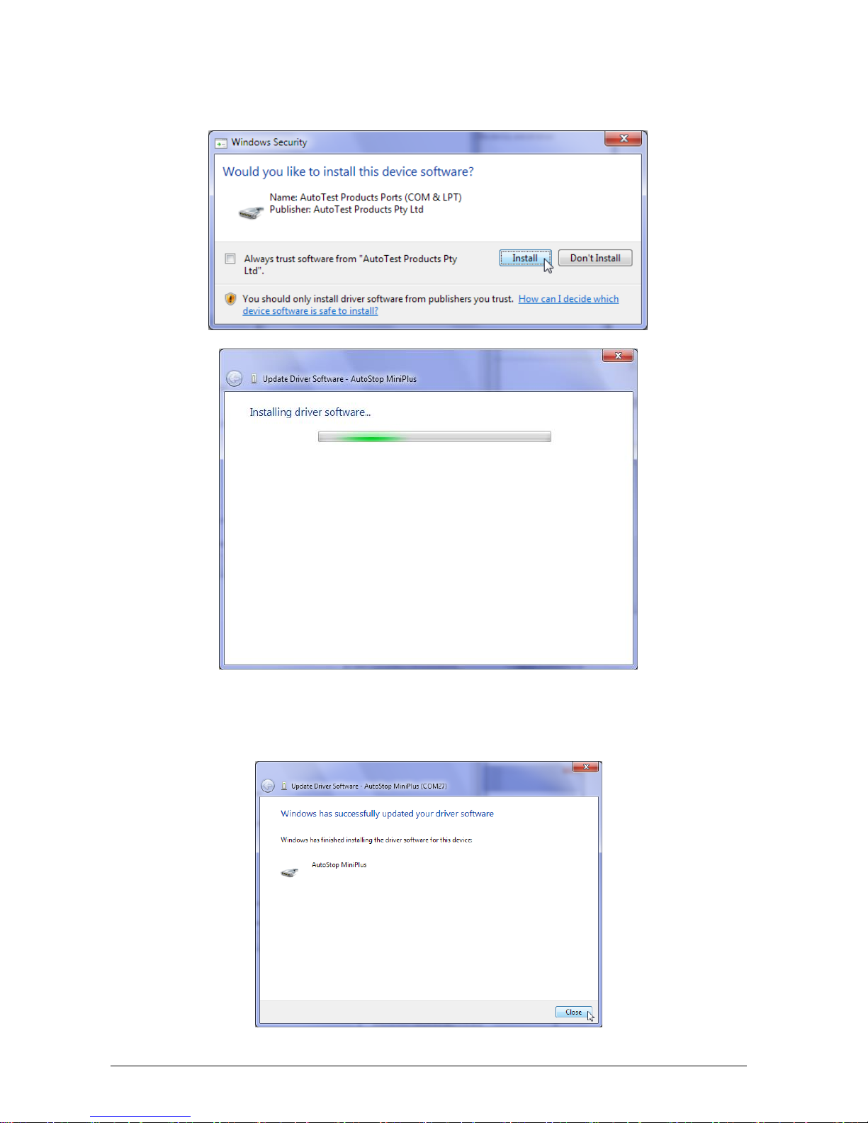
If the Windows displays the following warning message, select “Install this driver software
anyway”.
AutoStop Mini Plus User Manual v2.014 Page 16
If Windows prompts the following dialogue box, select “Install” to install drivers.
When Windows has completed installing the drivers for the USB interface, the following
window will appear. Notice the COM port number displayed on the titlebar. The COM port
will be used when downloading data from the meter using the datalogger software.
AutoStop Mini Plus User Manual v2.014 Page 17
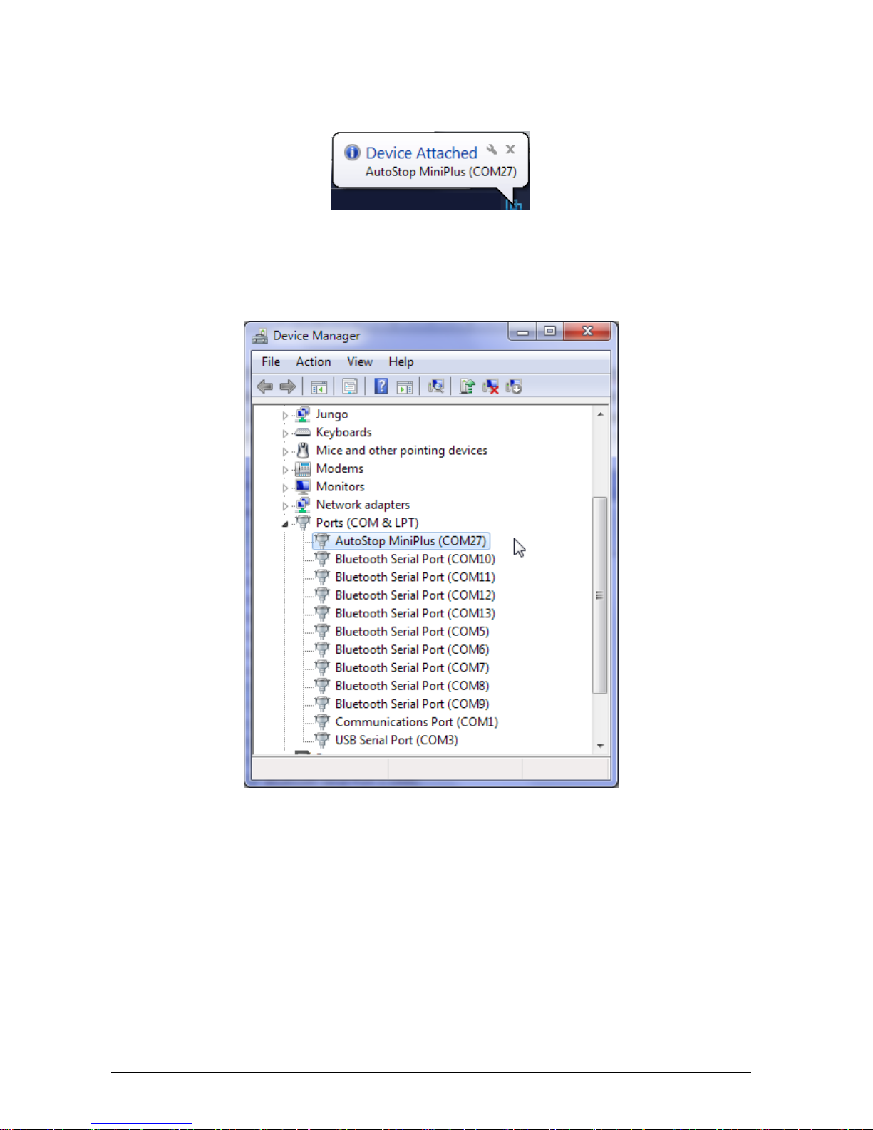
Once the USB drivers have been installed, Windows will diplay the following pop-up
message each time the brake meter is connected to the PC via USB interface.
To verify the installation of the USB driver, locate “AutoStop MiniPlus” in the device
manager under “Ports (COM & LPT)”. If the device drivers are successfully installed,
there will be a COM port number written next to the device name. In the following
example, the COM port number is “COM27”.
To download the results, open AutoStop Mini Plus datalogger software and click on
“Download” button.

AutoStop Mini Plus User Manual v2.014 Page 18
Select USB connection and then press Next.
Select the COM port of the USB connection. The COM port is the same port obtained
earlier during the USB drivers installation process. Make sure the brake meter switched
ON and it is connected to the PC via the USB cable. Press Next to continue.
Table of contents
Other AutoTest Test Equipment manuals


Popular Test Equipment manuals by other brands


Beta
Beta 1464AP Operation manual and instructions

High Voltage
High Voltage VLF-CM Series Safety, Operation, and Procedure Instructions

Gardner Bender
Gardner Bender CAM-10 operating instructions

Gossen MetraWatt
Gossen MetraWatt SECUTEST ST BASE operating instructions

Test-Um
Test-Um lanroverpro TP600 operating instructions

TKR Group
TKR Group VAS 652 005 Operation manual