AutoTest BST-380 User manual

BST-380 BATTERY TESTER
User’s Guide


1.1 Product Profile
The AutoTest BST-380 Battery System Tester uses advanced conductance testing
technology to easily, quickly and accurately measure the actual cold cranking amps
capability of the vehicle starting battery, the health of the battery itself, and common
faults in the vehicle starting system and charging system. It can help maintenance
personnel to identify problems quickly and accurately, thus leading to efficient vehicle
repair.
1. Can test all automotive cranking lead acid batteries, including ordinary lead acid,
AGM flat plate, AGM spiral, Gel battery, EFB battery and more.
2. Directly detect bad cells.
3. Polarity reverse connection protection, reverse connection will not damage the
tester or affect the vehicle and battery.
4. Test batteries for loss of electricity, no need to fully charge before testing.
5. Testing standards include a majority of the world’s battery standards, CCa, BCi,
Ca, mCa, JiS, Din, ieC, en, Sae and GB.
6. Supports multiple languages, the user can select different language packages
including: English, Chinese Simple, Chinese Traditional, Japanese, Russian,
Spanish, French, Italian, German etc. Other languages can also be customized
according to user’s requirements.
7. Has common additional functions such as a voltmeter, ammeter, thermometer, and
standby power for eCu.
8. Stores 100 groups of test data for check and print.
1.2 Product Function
The main functions of the AutoTest BST-380 Battery System Tester include: battery
testing, cranking tests, charging tests and other additional functions.
The battery test is usually used to analyze the battery health status, to calculate the
actual cold cranking capability of the battery and the aging extent, which provides
reliable analysis evidence for the test and maintenance of the battery. It notifies the user
to replace the battery in advance when the battery is getting old.
The cranking test is mainly used to test and analyze the starter motor. Through testing
the actual required cranking current and cranking voltage of the starter motor, it can
find out whether the starter motor is operating correctly. There are several reasons
why the starter motor might not operate as required: lubricating system faults causing
the starting loaded torque to increase or rotor friction of the starter motor resulting in
increasing friction within the unit itself.
Charging tests check and analyze the charging system, including the generator,
rectifier, rectifier diode etc. These tests determine if the output voltage of the generator
is normal, the rectifier diode works correctly and if the charging current is normal. If one
of the above mentioned parts is not operating normally, it can lead to an over-charge, or
incomplete charging of the battery, thus the battery can be quickly damaged and also
greatly shortened in life-span.
Chapter 1: Product Summary

Additional product functions include:
View test result, print test result, voltmeter, ammeter, thermometer and temperature
compensation, thermometer unit choice, QC mode, client code setting, set language, set
date and time format, date and time adjustment, set user info, screen light adjustment,
set printer definition and standby power function.
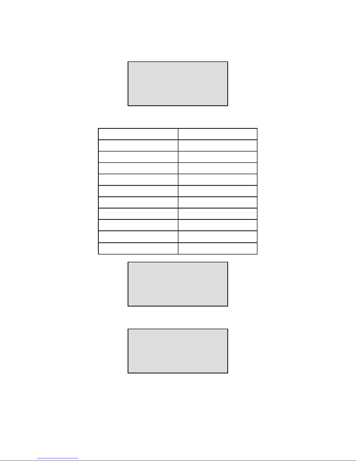
1.3 Technical Parameters
1) Cold Cranking Amps Measurement Range:
Measurement Standard Measurement Range
CCA 100 - 2000
BCI 100 - 2000
CA 100 - 2000
MCA 100 - 2000
JIS 26A17--245H52
DIN 100 - 1400
IEC 100 - 1400
EN 100 - 1400
SAE 100 - 2000
GB 100 - 1400
2) Voltage Measure Range: 1.0 to 30VDC.
3) Current Measure Range: 0 to 900A DC/AC.
4) Temperature Measure Range: -18°C to +70°C.
1.4 Working Enviornment
Working Environment Temperature: -20°C to 60°C
These specifications are suitable for automotive manufacturers, automotive maintenance
and repair workshops, automotive battery factories, automotive battery distributors, and
educational organizations etc.

Chapter 2: Tester Components
The AutoTest BST-380 consists of a battery tester main unit, testing cables and current
clamp. The main unit cover is made of ABS acid-resistant plastic.
BST-380 Start & Stop Battery System Tester User's Guide
- 03 -
CHAPTER 2: TESTER STRUCTURE
BST-380 mainly consists of battery tester main unit, testing cables and current clamp.
BST-380 Battery System Tester main unit cover is made of ABS acid-resistant plastic.
Removable testing cables Removable current clamp meter
CHAPTER 3: OPERATION PROCEDURE
3.1 Pre-Test
3.1.1 Connect Tester
● Before test, clean battery poles with metal wire brush and alkaline cleaner to avoid the
tolerance caused by oil and dust to the test result.
● For Group 31 or side-installed battery, connect and x the terminal wiring connector.
Otherwise, inaccurate test result will be caused due to wrong installation or dirty or
bad wiring connectors.
● While testing, ensure none of the in-vehicle electrical appliance is on, doors are
closed and the ignition key is in OFF status.
● Connect the red test clamp with battery anode and the black test clamp with cathode.
Shake the clamps back and forth to make sure they are well connected.
Tester requires the two clamps are well connected with the battery poles, otherwise,
the test cannot go on. When enter the battery test program, screen prompts "Check
Connection" (See below picture).Do clean the poles and re-connect in the right way.
Chapter 3: Operation Procedure
3.1 Pre-Test
3.1.1 Connect Tester
• Before running a test, clean the battery poles with wire brush and an alkaline
cleaner to avoid any changes in tolerance caused by oil and dust.
• For Group 31 or side-installed batteries, connect and fix the terminal wiring
connector otherwise an inaccurate test result will be caused due to incorrect
installation or dirty or bad wiring connectors.
• While testing, ensure that none of the in-vehicle electrical appliances are on, doors
are closed and the ignition key is in OFF position.
• Connect the red test clamp with the battery anode and the black test clamp with
the cathode.
Shake the clamps back and forth to make sure they are well connected.
The tester requires the two clamps to be well connected with the battery poles,
otherwise, the test can not commence. When you enter the battery test program, the
screen will prompt “Check Connection”. Clean the poles and re-connect correctly.
CHECK
CONNECTION

The tester has a reverse connection protection function. When clamps are accidentaly
connected in reverse, the tester will prompt “Reverse Connection” and it will damage
neither the testing unit nor the automotive load.
NOTE: For parallel connected batteries, break off the cathode connection first, then do a
single test to each battery. If the cathode connection is not cut off there will be errors
in test result.
3.1.2 Key Description
• Up and Down keys
Select upwards or downwards via white UP and DOWN keys.
• Return key
Return to previous menu via blue RETURN key.
• OK key
Confirm the selection via green OK key.
• MENU key
Enter additional function programs via MENU key.
• Power key
Turn on/off the tester. (Refer to 3.2 Tester Startup).
3.1.3 Connect Current Clamp
To test cranking amps and charging current, first connect the current clamp before
startup, then turn on the current clamp power switch.
After the tester starts up the current clamp is able to work.
Press the reset key of the current clamp and connect the current clamp jaw to the
anode wiring between the battery to be tested and the generator. See next picture.
As the minimum width of the current clamp jaw is only 28mm, choose the connection
cable or connection pole with a diameter less than 28mm to test. Otherwise, the current
clamp jaw cannot close completely.
REVERSE
CONNECTION

NOTE:
1. Current clamp jaw must close to avoid test tolerance.
2. Current clamp uses 9V alkaline battery. Turn the clamp power off after using the
current clamp.
3. Before testing the current, take off the current clamp from the battery positive
connection cable, and reset.
3.2 Tester Startup
The tester will start up after pressing the power key, and display the customized logo
interface (Default voltmeter is ON) refer to figure 1.
At the bottom left of the startup interface, “ “ shows the real time capacity of the internal
9V battery. When the capacity of the 9V battery is not sufficient, replace it in
time to avoid any impact on the use of the additional functions.
By default, at the middle bottom of the startup interface, it displays the voltmeter
value, which can be used as DC voltmeter. The DC voltmeter measurement range is 1.0
to 30VDC. (Caution: Over this measurement range, it may damage the tester.)
SLIVERADO
Battery system tester
12.64V
Figure 1, Startup Interface with Voltmeter On

The voltmeter function can be set as “ON/OFF” in the voltmeter under “Additional
Functions”.
When the voltmeter is ON and no other operations are in progress after tester startup,
the screen will display the startup interface all the time. In this situation, it can be used
as a DC Voltmeter. When the OK key is pressed, the tester enters the battery test
program. If you press the MENU key, it enters additional function programs.
When the voltmeter is OFF the screen shows the startup interface as below in figure 2.
After 2 seconds, it automatically enters the battery test program. Press the MENU key
within these 2 seconds and it will enter additional function programs.
3.3 Battery Test
After entering the battery test program the tester displays the tester model and version
for approx. 2 seconds, see figure 3.
3.3.1 IN-VEHICLE or OUT-OF-VEHICLE
Press the UP/DOWN key to select the battery location, in vehicle or out of vehicle, then
press the OK key to confirm.
1) IN-VEHICLE means battery is connected with the vehicle generator or vehicle
electrical appliance.
The bottom line of the interface shows the current date and time, this format
can be edited and adjusted in the additional functions.
For details, refer to Additional Function 3.8.10 “Set Date and Time” and 3.8.11 “Date
and Time Adjustment”. The tester will display the following instructions in a sequence,
select accordingly.
SELECT TEST
IN-VEHICLE
SLIVERADO
Battery system tester
BST-380
Version: 1.00.000
2012-11-02 14.31
Figure 2, Startup Interface with Voltmeter Off
Figure 3, Interface with tester model and version

When a surface charge is detected by the tester, it prompts “SURFACE CHARGE
DETECTED, TURN LIGHTS ON”.
Turn lights on as prompted to eliminate the battery surface charge, the tester will then
display the following messages in a sequence:
Now that the detection of the surface charge has been eliminated, turn lights off as
prompted, then press the OK key. The tester will recover automatically.
2) OUT-OF-VEHICLE means the battery is not connected with any of the vehicle loaded,
i.e. battery connection is cut off.
3.3.2 Select Battery Charge State
After selecting the battery location, the tester will prompt to select the battery charge
status, i.e. Before Charge or After Charge.
Press the UP/DOWN key to the select battery charge status, then press the OK key to
confirm. This process ensures a more accurate test result.
NOTE: Select Before Charge for Cold Vehicle and After Charge for Hot
Vehicle.
SURFACE CHARGE
DETECTED
TURN LIGHTS ON
HEADLIGHTS ON
TURN LIGHTS OFF
SELECT TEST
OUT-OF-VEHICLE
SELECT CHARGE
BEFORE CHARGING
SELECT CHARGE
AFTER CHARGING

3.3.3 Select Battery Type
After the battery charge status is selected, the tester will prompt to select battery type,
i.e. Regular Flooded, AGM Flat Plate or AGM Spiral, Gel battery or EFB battery.
Press the UP/DOWN key to select the battery type, and press OK key to confirm.
When it is an IN-VEHICLE test, the battery installation method will also be selected, e.g.
TOP, SIDE or REMOTE (This selection is not required for OUT-OF-VEHICLE), then press
the OK key to confirm.
REMOTE is adopted for some in vehicle batteries which are too tightly installed to use
the test clamps to connect the battery poles.
SELECT TYPE
REGULAR FLOODED
SELECT TYPE
AGM FLAT PLATE
SELECT TYPE
AGM SPIRAL
SELECT TYPE
GEL
SELECT TYPE
EFB

NOTE: For REMOTE test, there will be a little tolerance. For any doubt, take off the
battery and select “OUT-OF-VEHICLE” to re-test.
3.3.4 Battery System Standard and Rating
The AutoTest BST-380 Battery System Tester will test each battery according to the
selected system and rating.
Use the UP/DOWN key to make a selection according to the actual system standard
and rating marked on the battery. See the arrow indicating it’s location in the below
picture.
• CCA: Cold Cranking Amps, specified by SAE&BCI, most frequently used value for
starting battery at 0°F (-18°C).
• BCI: Battery Council International standard.
• CA: Cranking Amps standard, effective starting current value at 0°C.
• MCA: Marine Cranking Amps standard, effective starting current value at 0°CJapan
Industrial Standard, displayed on the battery as combination of the numbers and
letters, e.g. 55D23,80D26.
• DIN:German Auto Industry Committee Standard.
• IEC:Internal Electro technical Commission Standard.
SELECT TYPE
TOP POST
SELECT TYPE
SIDE POST
SELECT TYPE
REMOTE
• EN: European Automobile Industry Association Standard.
• SAE: Society of Automotive Engineers Standard.
• GB China National Standard.
The Rating ranges are as follows:
Measurement Standard Measurement Range
CCA 100 - 2000
BCI 100 - 2000
CA 100 - 2000
MCA 100 - 2000
JIS 26A17--245H52
DIN 100 - 1400
IEC 100 - 1400
EN 100 - 1400
SAE 100 - 2000
GB 100 - 1400
Input correct test standard and rating, press OK key, tester starts to test, and
the display will prompt with “TESTING”. See below.
It takes approx. 3 seconds to display the battery test result.
SELECT INPUT
CCA
SELECT RATING
500A CCA
TESTING
***

3.3.5 Battery Test Result
Battery test results include 5 types as follows:
1. Good Battery
The battery is without any problems.
NOTE: SOH means State of Health. SOC means State of Charge.
2. Good, Recharge
Good battery but low current, recharge before using.
3. Replace
The battery is near to or has already reached the end of usable life, replace battery.
4. Bad Cell, Replace
Battery interior damaged, broken cell or short circuit, replace battery.
5. Charge, Retest
An unstable battery should be recharged and retested to avoid errors. If the
same test result appears after a recharge and retest, the battery is considered as
damaged, replace the battery.
NOTE: If “Replace” resulted from IN -VEHICLE mode, it might be that the vehicle
cable is not well connected with the battery. Ensure to cut off the cable and retest
the battery under OUT-OF-VEHICLE mode before making a decision to replace it.
SOH:96% SOC:98%
12.64V 490A
Rating 500A
GOOD BATTERY
SOH:78% SOC:30%
12.20V 440A
Rating 500A
GOOD, RECHARGE
SOH:46% SOC:80%
12.68V 340A
Rating 500A
REPLACE
SOH:0% SOC:20%
10.60V 0A
Rating 500A
BAD CELL, REPLACE
SOH:39% SOC:20%
12.08V 310A
Rating 500A
CHARGE, RETEST

NOTE: After testing, if you need to return, press RETURN key to directly return to the
startup interface.
After the battery test:
If it is in “OUT-OF-VEHICLE” test state, press OK key, it will print the test result.
If it is in “IN-VEHICLE” test state, press OK key to bring up the Cranking Test.
3.4 Cranking Test
Connect with current clamp in advance.
A bad connection will cause the tester to not test the actual cranking amps accurately.
Refer to 3.1.3 for current clamp connection.
Starting the engine as prompted, the tester will automatically complete the cranking test
and display the result.
Normally, cranking voltage values lower than 9.6V are regarded as abnormal, higher than
9.6V is OK.
Test result includes actual cranking voltage, actual cranking amps, and actual cranking
time.
When the cranking test is abnormal, the battery test results will also be displayed at the
same time as per the image below.
This is for the convenience of the maintenance personnel to quickly know the whole
state of the starting system according to the data.
After testing is finished, do not shut down the engine, press OK key to enter the
Charging Test.
CRANKING TEST
START ENGINE
RPM DETECTED
TIMES 780ms
AMPS 540A
CRANKING NORMAL
10.13V
TIMES 1020ms
AMPS 320A
CRANKING LOW
REPLACE 9.12V

3.5 Charging System and Rectifier Diode Test
When entering the charging test, the tester will prompt “Charging Test?”
Press the OK key again to start the charging test.
NOTE: Do not shut down the engine during the test. All electrical appliances and
devices are in the OFF state. Turning on/off any electrical appliance in the vehicle during
the test will affect the accuracy of the test result.
The tester will do the following tests in a sequence:
For a ripple test, the tester will display the real time ripple and showsripple volt and
charging volt values at the bottom line.
It takes approx. 6 seconds for the ripple test.
After the ripple test, tester will automatically start the loaded voltage test.
Loaded Volt Testing takes approx. 3 seconds, then it hints “Step on accelerator to
increase engine rotating speed”. See below picture:
Operate accordingly to increase the engine rotating speed to 3000 turns or above, and
keep for 5 seconds.
CHARGING TEST?
LOADED TESTING
RIPPLE TEST
35nV 14.12V
INCREASE REV

The tester will start the charging volt test after an increase in rev’s is detected.
After the test is finished, the tester displays the effective charging volts, ripple test result
and charging test result.
NOTE: If no increase in rev’s is detected, it could be the fault of generator, regulator or
connection with battery. The tester will try 3 times to further, if it still faileds, it will skip
the increase in rev’s detection and the test result displays “No Volt Output”.
Check the connection between generator and battery, then retest.
Charging Test Result:
1. Charging Volt: Normal
Charging system shows the generator output to be normal, no problem detected.
2. Charging Volt: Low
Charging volt of the charging system is low.
Check drive belt of the generator for slip or running off. Check the connection
between the generator and the battery is normal. If both the drive belt and the
connection are in good condition, follow the manufacturer’s suggestions to
eliminate generator faults.
3. Charging Volt: High
Generator output volt is high.
Since most of the vehicle generators use an internal regulator, the generator
assembly has to be replaced. (Some old style cars use an external regulator, then
directly replace the regulator.) The normal high voltage of the voltage regulator
is a maximum of 14.7±0.5V. If the charging volt is too high, it will overcharge the
battery. Therefore, the battery life will be shortened and troubles may result.
4. No Volt Output:
No generator volt output is detected. Check the generator connection cable, the
drive belt of the generator and the engine.
5. Diode Test:
Through the test of charging current ripple, the tester will find out whether the
diode is normal or not. When ripple volt is too high, it proves at least one diode is
TESTING
***
CHARGING NORMAL
LOADED 14.18V
LOADED 14.36V
RIPPLE NORMAL
NO OUTPUT
LOADED 12.81V
LOADED 12.81V
RIPPLE NORMAL

damaged. Check and replace the diode. Until now, all tests have been done.
If client code setting function is off, press the OK key again, it will then prompt
“Print Result?”, press OK key to print.
If client code setting function is on, press OK key again, it will then prompt “Print
Result?”, press the OK key to input the client code. After client code input, press
the OK key again, it will prompt “Print Result?”, press the OK key to print.
3.6 Client code Input
Client code in a sequence, 1st to 7th digits are letters or numbers. When pressing UP/
DOWN keys, numbers and letters will be displayed in a scrolling manner, select the
number or letter needed, press OK key to confirm and carry on the input for the next
digit.
For example, to input “BA8888”.
Press the UP/DOWN key to select the first Chinese character “BA”, press OK to finish
the first digit input.
Press the UP/DOWN key to select the second letter “B”, press OK to finish the second
digit input.
Continue unil the 7th digit input is finished.
Press the OK key again, the tester will print out the test result including the plate
number.
NOTE: For languages other than Chinese, the client code input method is the same (first
digit changed to number or letter).
CLIENT CODE
AA88888
CLIENT CODE
BA88888
CLIENT CODE
BB88888
CLIENT CODE
BB4F50N

3.7 24V System Test
An ordinary 24V battery group combines two 12V batteries in a series connection.
Therefore, when testing a 24V battery, the tester will prompt “24V Battery”, divide
the batteries and test one by one. It’s not necessary to break off the connection
cable (Comparatively, the parallel connected battery group must cut off the cathode
connection), the test method is the same as testing a single 12V battery.
For 24V charging and cranking tests, connect the red clamp to the anode of the 24V
battery group and the black clamp to the cathode of the 24V battery group.
NOTE: It’s nott he anode and cathode of the single battery but the battery group), select
IN-VEHICLE, screen displays “24V Battery”, ignore the prompt, after 3 seconds, the
tester will skip the battery test program and enter the cranking test. Follow the method
of a 12V system test to complete the 24V charging and cranking tests. The test process
is same as with a12V system.
3.8 Additional Functions
Press MENU key to enter Additional Function (See 3.2 Tester Startup). Following options
and operation can be done.
3.8.1 View Results
View results from the last test by pressing OK key.
3.8.2 Print Results
Tester can view the latest 100 groups of test data, and print out any group for
reference via the thermal printer. Press OK key to enter.
Search the test results by date and time, then press the OK key.
24V BATTERY
OPTION SELECT
1. VIEW RESULTS
OPTION SELECT
2. PRINT RESULTS
DATA 016
2012-10-11 11.30

NOTE: When internal memory is full, the tester will automatically clear the earliest test
results. Alternatively select “Memory Reset” under “QC Mode” in Additional Functions to
clear all data in memory and store data all over again.
NOTE: Once reset, all data will be cleared and cannot be recovered.
3.8.3 Voltmeter
The AutoTest BST-380 Battery System Tester can also be used as DC voltmeter.
The working range is 1.0-30V DC.
CAUTION: The AutoTest BST-380 unit can be damaged when connected to voltages
above 30V!
This function can set the voltmeter On/Off at the bottom line of the startup interface.
After successful setup, it shows “OK” for 2 seconds, then returns to the previous
interface.
3.8.4 Ammeter
The tester can be used as an ordinary ammeter via the attached current clamp.
Press OK key to display the ammeter interface.
CAUTION:
1. Turn the current clamp power off as soon as the ammeter test is done, otherwise it
will shorten the life of the internal battery.
2. Before each test, take off the current clamp from the anode and reset.
OPTION SELECT
3. VOLTMETER
OPTION SELECT
4. AMMETER
AMMETER
250A

OPTION SELECT
5. THERMOMETER
82.36°F
OPTION SELECT
6. TEMP UNIT
CHOICE
OPTION SELECT
7. QC MODE
3.8.5 Thermometer
The tester has an integrated internally temp sensor, which detects the ambient
environment temperature.
Press the OK key to display the thermometer interface.
3.8.6 Thermometer Unit Choice
This option is to set Fahrenheit or Celsius.
First, press the OK key one time, then use the UP/DOWN arrow to choose °C or °F. After
successful setup, it displays “OK” for 2 seconds, then will return to the previous
interface.
3.8.7 QC Mode
In QC mode the tester will simplify the test input process, which makes the battery test
much faster and easier. The tester will count the test for the purpose of analyzing
and tracking battery quality.
This function is applicable for vehicle manufacturers and maintenance workshops to
test and analyze the a purchased battery, and also for battery factory’s to inspect and
analyze outgoing batteries. QC function is off by default.
After successful setup, the unit will display “OK” for 2 seconds, then return to the
previous interface. In addition, memory reset in QC mode will clean all stored data,
including the 100 groups of data viewed in “Print Results”. Once reset, data cannot be
recovered.
Table of contents
Other AutoTest Test Equipment manuals


Popular Test Equipment manuals by other brands


Beta
Beta 1464AP Operation manual and instructions

High Voltage
High Voltage VLF-CM Series Safety, Operation, and Procedure Instructions

Gardner Bender
Gardner Bender CAM-10 operating instructions

Gossen MetraWatt
Gossen MetraWatt SECUTEST ST BASE operating instructions

Test-Um
Test-Um lanroverpro TP600 operating instructions

TKR Group
TKR Group VAS 652 005 Operation manual