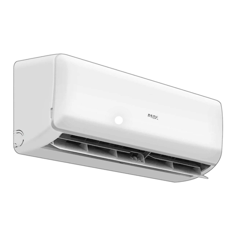
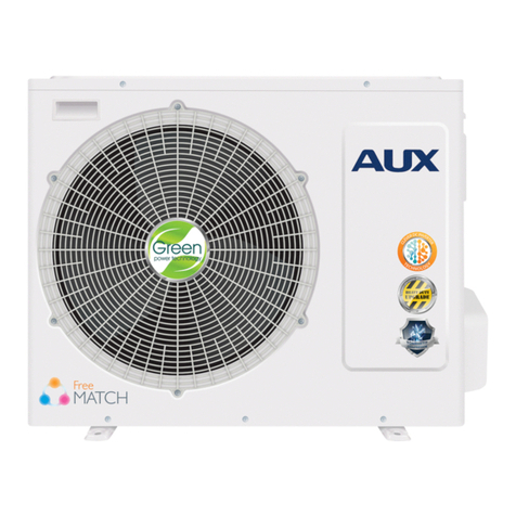
AUX Europe Series User manual

Service manual
Europe Series
(DC Inverter 1 Drive 1 50Hz R32)
ΑΓΗΝΩΡ A.E.
ΟΜΙΛΟΣ ΕΤΑΙΡΙΩΝ ΤΟΥΡΝΙΚΙΩΤΗ
ΓΕΝΙΚΟΙ ΑΝΤΙΠΡΟΣΩΠΟΙ

R32 High Efficiency DC Inverter LCAC
Contents
Contents ......................................................................................................... 2
Part1 General information ............................................................................. 1
1. Nomenclature ............................................................................................................ 1
2. Unit appearance ........................................................................................................ 2
Part2 Features ................................................................................................ 4
1. Outdoor Units ............................................................................................................ 4
2. Four-way Cassette .................................................................................................... 5
3. Ceiling Floor .............................................................................................................. 6
4. Constant Duct ............................................................................................................ 7
Part3 Piping System .................................................................................... 10
Part4 Specification ...................................................................................... 11
1. Cassette .................................................................................................................. 11
2. Ceiling Floor ............................................................................................................ 17
3. Duct ......................................................................................................................... 23
4. Outdoor Unit ............................................................................................................ 29
Part5 Dimension .......................................................................................... 35
1. Cassette .................................................................................................................. 35
2. Ceiling Floor ............................................................................................................ 37
3. Duct ......................................................................................................................... 38
4. Outdoor Unit ............................................................................................................ 40
Part6 Electrical Principle Diagram .............................................................. 44
1. Cassette .................................................................................................................. 44
2. Ceiling Floor ............................................................................................................ 46
3. Duct ......................................................................................................................... 47
4. Outdoor Unit ............................................................................................................ 48
Part7 Capacity Amendment ........................................................................ 51
1. Operation range ....................................................................................................... 51
2. Capacity amendment of different ambient temperature ........................................... 51
3. Long piping length ................................................................................................... 53
4. Capacity amendment of different piping length ........................................................ 54
5. Equivalent Pipe length conversion ........................................................................... 55
Part8 Static pressure curve ........................................................................ 56

R32 High Efficiency DC Inverter LCAC
3
1. 18K Duct .................................................................................................................. 56
2. 24K Duct .................................................................................................................. 57
2. 30K Duct .................................................................................................................. 58
2. 36K/42K Duct .......................................................................................................... 59
3. 48K/60K Duct .......................................................................................................... 60
Part9 Control ................................................................................................ 61
1. Controller ................................................................................................................. 61
2. Parameters Setting .................................................................................................. 85
3. Room Card Function ............................................................................................... 90
4. Wifi Module .............................................................................................................. 93
5. Static Pressure setting ............................................................................................. 96
Part10 Explosive View ............................................................................... 100
1. Cassette ................................................................................................................ 100
2. Ceiling Floor .......................................................................................................... 107
3. Duct ....................................................................................................................... 115
4. Outdoor Unit .......................................................................................................... 119
Part11 Installation ...................................................................................... 129
1. Preparation ............................................................................................................ 129
2. Precaution ............................................................................................................. 130
3. Cassette installation .............................................................................................. 130
4. Ceiling Floor installation......................................................................................... 135
5. Duct installation ..................................................................................................... 137
6. Outdoor Unit installation ........................................................................................ 140
7. Connection piping installation ................................................................................ 142
8. Emptying or Vacuum .............................................................................................. 145
9. Insulation ............................................................................................................... 146
10. Additional refrigerant charge ................................................................................ 148
11. Electrical connection ............................................................................................ 149
Part12 PCB Instruction .............................................................................. 153
1. Outdoor Unit PCB .................................................................................................. 153
2. Indoor Unit PCB ..................................................................................................... 156
Part13 Trouble Shooting ........................................................................... 158
1. Failure code display ............................................................................................... 158
2. Failure analysis ...................................................................................................... 159


R32 High Efficiency DC Inverter LCAC
1
Part1 General information
1. Nomenclature
Indoor Unit
Outdoor Unit

R32 High Efficiency DC Inverter LCAC
2. Unit appearance
2.1 Cassette
Cassette Body
Model
Panel
Standard
Optional
ALCA-H12/NDR3HAA
MB13-I
MB09
ALCA-H18/NDR3HAA
ALCA-H24/NDR3HAA
MB12
MB08
ALCA-H36/NDR3HAA
ALCA-H42/NDR3HAA
ALCA-H48/NDR3HAA
ALCA-H60/NDR3HAA
2.2 Ceiling floor
PICTURE
Capacity
Model
18k/Btu
ALCF-H18/NDR3HA
24k/Btu
ALCF-H24/NDR3HA
36k/Btu
ALCF-H36/NDR3HA
42k/Btu
ALCF-H42/NDR3HA
48k/Btu
ALCF-H48/NDR3HA
60k/Btu
ALCF-H60/NDR3HA
2.3 Duct
PICTURE
Capacity
Model

R32 High Efficiency DC Inverter LCAC
3
18k/Btu
ALMD-H18/NDR3HA
24k/Btu
ALMD-H24/NDR3HA
30k/Btu
ALMD-H30/NDR3HA
36k/Btu
ALMD-H36/NDR3HA
42k/Btu
ALMD-H42/NDR3HA
48k/Btu
ALMD-H48/NDR3HA
60k/Btu
ALMD-H60/NDR3HA
2.4 Outdoor Units
Capacity
(BTU)
Picture
Capacity
(BTU)
Picture
12K、18K
24K
30K、36K、42k
48K、60k

R32 High Efficiency DC Inverter LCAC
Part2 Features
1. Outdoor Units
Environmental-friendly Refrigerant R32
The GWP value of R32 is smaller,so the effect on the greenhouse effect is smaller.The
ODP value of R32 is 0,so it’s no harm to our planet’s ozone layer.
High Efficiency
Equipped with high efficiency DC Inverter compressor, adjustable fan motor and
advanced 180° sine wave vector driver, the system can be higher than 6.1 in SEER and 4.0
in SCOP so as to meet the European and Australian new energy efficiency standards.
Reliability
Stable cooling under -15°C and heating under -15°C outdoor environment
temperature.
180°Sine Wave Control
DC inverter compressor uses 180°sine wave vector control technique, make
compressor motor operate smoothly and efficiency increases significantly.
Optimized Pipeline Design
The design ensures the sub-cooling and enhances the cooling capacity by separating
the refrigerant inlet and outlet.
Simulation Technology
Via analysing piping stress distribution, piping amplitude and displacement in
transportation and operation, the reliability has been improved greatly.

R32 High Efficiency DC Inverter LCAC
5
2. Four-way Cassette
Four-way cassette type A/C is installed under the ceiling, compared with Floor
&Standing type A/C, it has following advantages: Ceiling installation combining with the
decoration, makes the room more elegant; Flexible installation in anywhere in the ceiling
and 4-direction blowing, makes you feel more comfortable.
Built-in Drain Pump
The built-in drain pump can lift condensing water up to 1200mm high from the drainage
pan.
Fresh Air Intake
Fresh air makes indoor air healthy and comfortable.
Optimized Electric Box
Better fire-proof and easy to maintenance.
① Fresh Air Intake
② Optimized Electric Box
①
②

R32 High Efficiency DC Inverter LCAC
3. Ceiling Floor
Ceiling& Foor type A/C can be installed under the ceiling and also on the floor.
Compared with normal Floor &Standing type A/C, it can be hoisted under the ceiling,saving
room space, it is also the updating Product for Floor & Standing type A/C.
3D Air Swing
Vertical and horizontal swing makes air below to every corner of the room.
Ultra Slim Design
The thickness is only 205mm, save installation space.
Innovative Centrifugal Fan
Innovative centrifugal fan provides larger air volume but lower noise, making the air
supply more quietly and smoothly.
Flexible Installation
Can be vertically installed against the wall or horizontally installed under the ceiling.

R32 High Efficiency DC Inverter LCAC
7
4. Constant Duct
Constant Air Flow Volume
Under different ESP, the product supply Constant air flow volume for comfort.
Integrate the control board and power board
High reliability

R32 High Efficiency DC Inverter LCAC
Two-way drain pan
Independently designed bottom flange
Independently designed bottom flange,The air duct will not be damaged in mainteance
Easy for mainteance
Easy disassembly filter
0 Screws,Easy disassembly, convenient for wash ,W type high effeciency filter

R32 High Efficiency DC Inverter LCAC
9
Optimized Centrifugal Fan
Removable Control Box

R32 High Efficiency DC Inverter LCAC
Part3 Piping System
The compressor inhales the low-temperature and low-pressure refrigerant vapor
from the evaporator, and vapor be turned into high-temperature and high-pressure gas
then enters into condenser, the high-temperature and high-pressure refrigerant gas and
outdoor air make heat exchange in the condenser, the compressed vapor is then cooled
by heat exchange with the outside air, so that the vapor condenses to be a
high-temperature and high-pressure fluid, and then through capillary throttling to cooled,
low pressure, then the liquid enters into the evaporator and two-phase of gas and liquid
refrigerant in the evaporator completely evaporate, thereby cooling the indoor air; from
evaporator the vapor is inhaled into compressor again, so it runs continuously cycle to
cycle, cooled air is continuous supplied to the air-conditioned area though duct by fan
motor.
T-suction
T-discharge
T-defrost
Filter
T-indoor coilT-indoor ambient
Stop valve (liquid) EEV
T-Condenser
middle
T-outdoor
Fan
ambient
High Pressure
Switch
Low Pressure
Switch
inverter
Fan
Evaporator Stop valve (gas) Condenser
Four-way valve
Filter

R32 High Efficiency DC Inverter LCAC
11
Part4 Specification
1. Cassette
1.1 12K, 18K,24K, 36K,
Model
Indoor
ALCA-H12/NDR3HAA
ALCA-H12/NDR3HAB
ALCA-H18/NDR3HAA
ALCA-H18/NDR3HAB
ALCA-H24/NDR3HAA
ALCA-H24/NDR3HAB
ALCA-H36/NDR3HAA
ALCA-H36/NDR3HAB
Panel
MB09 MB13
MB09 MB13
MB08 MB12
MB08 MB12
Outdoor
AL-H12/NDR3A(U)
AL-H18/NDR3A(U)
AL-H24/NDR3A(U)
AL-H36/NDR3A(U)
Factory Model
Indoor
ALCA-H12A4/R3VDS1-
C2
ALCA-H18A4/R3VDS1-
C2
ALCA-H24A4/R3VDS1-
C2
ALCA-H36A4E5/R3VDS1-
C2
Outdoor
AL-H12A4/R3VDS1-C2
AL-H18A4/R3VDS1-C2
AL-H24A4/R3VDS1-C2
AL-H36A4/R3VDS1-C2
Power Supply
V~,Hz,P
h
220-240/50/1
220-240/50/1
220-240/50/1
220-240/50/1
Capacity
Cooling
Btu/h
12000(4600-15000)
18000(5200-19100)
24000(7400-28000)
36000(9800-44300)
KW
3.60(1.35-4.40)
5.00(1.53-5.60)
7.00(2.16-8.20)
10.55(2.9-13)
Heating
Btu/h
14300(4200-18100)
19100(4800-21200)
27300(6800-31700)
38000(8800-46000)
KW
4.20(1.24-5.30)
5.60(1.40-6.20)
8.00(1.98-9.30)
11.15(2.6-13.5)
Electric Data
Rated Cooling Power
Input
KW
1.08(0.26~1.60)
1.63(0.47~2.30)
2.18(0.67-3.56)
3.4(0.71-4.71)
Rated Heating Power
Input
KW
1.23(0.19~1.51)
1.73(0.46~2.25)
2.10(0.65-3.62)
3.45(0.47-4.13)
Rated Cooling
Current
A
4.74(1.1~5.76)
7.16(2.25~10.10)
9.57(3.21-15.63)
15(3.2-21.5)
Rated Heating
Current
A
5.40(0.78~6.6)
7.60(2.20~9.88)
9.22(3.11-15.90)
15.5(2.43-18)
Performance
EER/COP
W/W
3.33/3.41
3.07/3.24
3.21/3.81
3.10/3.23
SEER/SCOP
W/W
6.2/4.1
6.3/4.0
6.5/4.2
6.1/4.0

R32 High Efficiency DC Inverter LCAC
Indoor Fan
Motor
Model
XD30C-ZL
XD30C-ZL
XD50B-ZL
XD100A-ZL
Brand
Panasonic
Panasonic
Panasonic
Panasonic
Output Power x Fan
quantity
W
30×1
30×1
50×1
100*1
Capacitor
uF
/
/
/
/
Speed (Hi/Mi/Lo)
r/min
750/700/650
750/700/650
530/470/420
700/600/550
Indoor Coil
a.Number Of Row
2
2
2
2
b.Tube Pitch(a)x Row
Pitch(b)
mm
20.5×12.7
20.5×12.7
16.32×12.7
16.32×12.7
c.Fin Pitch
mm
1.5
1.5
1.6
1.4
d.Fin Material
Hydrophilic aluminum fin
e.Tube Outside
Dia.and Material
mm
φ7, Inner grooved
φ7, Inner grooved
φ7, Inner grooved
φ7, Inner grooved
f.Coil Length x Height
x Width
mm
1322×205×25.4
1322×205×25.4
2044×205×25.4
2074×494×25.4
g.Heat Exchanging
Area
m2
5.76
6.12
12.7
11.63
Indoor Unit
Indoor Air Flow
(Hi/Mi/Lo)
m3/h
700/600/530
700/600/530
1300/1050/950
1800/1550/1350
Sound Pressure
Noise Level
(Hi/Mi/Lo)
dB(A)
45/44/36
45/44/36
47/43/38
51/48/45
Sound Power Noise
Level
dB(A)
56
56
57
62
Net Dimension
(W*H*D)
mm
570×570×260
570×570×260
835×835×250
835×835×290
Packing Dimension
(W*H*D)
mm
655×655×295
655×655×295
910×910×310
910×910×350
Net Weight
Kg
17
17
24
26.5
Gross Weight
Kg
20
20
27.5
30.5
Panel
Net Dimension
(W*H*D)
mm
650×650×55
650×650×55
950×950×55
950×950×55
Packing Dimension
(W*H*D)
mm
710×710×80
710×710×80
1000×1000×100
1000×1000×100
Net weight
Kg
2.2
2.2
5.3
5.3

R32 High Efficiency DC Inverter LCAC
13
Gross weight
Kg
3.7
3.7
7.8
7.8
Refrigerant Pipe
Liquid Side
mm
6.35(1/4)
6.35(1/4)
9.52(3/8)
9.52
Gas Side
mm
12.7(1/2)
12.7(1/2)
15.88(5/8)
15.88
Drainage
mm
R3/4in(DN20)
R3/4in(DN20)
R3/4in(DN20)
R3/4in(DN20)
Max. Refrigerant Pipe
Length
m
25
30
50
65
Max. Difference In
Level
m
10
20
25
30
Operation Temperature Range
℃
16~32
16~32
16~32
16~32
Ambient
Temperature
Range(Cooling/H
eating)
℃
-15~52/-15~24
-15~52/-15~24
-15~52/-15~24
-15~52/-15~24
Connection
Wiring
Power
Wiring( Indoor)
mm2
3*1.5
3*1.5
3*1.5
3*1.5
Power
Wiring( Outdoor)
mm2
5*2.5
5*2.5
5*2.5
5*2.5
Signal Wiring
mm2
2*0.2
2*0.2
2*0.2
2*0.2
Wireless Remote Controller
YKR-L/300-HYE
YKR-L/300-HYE
YKR-L/300-HYE
YKR-L/300-HYE
Qty’per 20’& 40’&40HQ(Only For
Reference)
Set
66/139/165
66/139/165
36/76/86
27/62/66

R32 High Efficiency DC Inverter LCAC
1.2 42K, 48K,60K
Model
Indoor
ALCA-H42/NDR3HAA
ALCA-H42/NDR3HAB
ALCA-H48/SDR3HAA
ALCA-H48/SDR3HAB
ALCA-H60/SDR3HAA
ALCA-H60/SDR3HAB
Panel
MB08 MB12
MB08 MB12
MB08 MB12
Outdoor
AL-H42/NDR3A(U)
AL-H48/SDR3A(U)
AL-H60/SDR3A(U)
Factory Model
Indoor
ALCA-H42A4E5/R3VDS1-C2
ALCA-H48A5E5/R3VDS1-C2
ALCA-H60A5E5/R3VDS1-C2
Outdoor
AL-H42A4/R3VDS1-C2
AL-H48A5/R3VDS1-C2
AL-H60A5/R3VDS1-C2
Power Supply
V~,Hz,Ph
220-240/50/1
380-415/50/3
380-415/50/3
Capacity
Cooling
Btu/h
42000(9800-46000)
48000(16241-56298)
55000(16241-59710)
KW
12.1(2.9-13.5)
14.00(4.76-16.5)
16.00(4.76-17.5)
Heating
Btu/h
46000(8800-51100)
55000(16309-55104)
58000(16308-63122)
KW
13.5(2.6-15)
16.00(4.78-16.15)
17.00(4.78-18.50)
Electric Data
Rated Cooling
Power Input
KW
4.5(0.71-5.1)
5.20(1.71-6.7)
6.10(1.71-6.8)
Rated Heating
Power Input
KW
4.6(0.47-4.53)
5.40(1.71-6.8)
5.80(1.71-7.1)
Rated Cooling
Current
A
19.5(3.2-22.3)
22.6(7.4~28.6)
26.5(7.4~29.1)
Rated Heating
Current
A
20(2.43-19.7)
23.4(7.4~29.1)
25.2(7.4~29.5)
Performance
EER/COP
W/W
2.69/2.93
2.69/2.96
2.62/2.93
SEER/SCOP
W/W
6.1/4.0
6.1/4.0
6.1/4.0
Indoor Fan Motor
Model
XD100A-ZL
XD100A-ZL
XD100A-ZL
Brand
Panasonic
Panasonic
Panasonic
Output Power x
Fan quantity
W
100*1
100*1
100*1
Capacitor
uF
/
/
/
Speed
(Hi/Mi/Lo)
r/min
700/600/550
700/600/550
700/600/550
Indoor Coil
a.Number Of Row
2
3
3
b.Tube Pitch(a)x
Row Pitch(b)
mm
16.32×12.7
20.5×12.7
20.5×12.7

R32 High Efficiency DC Inverter LCAC
15
c.Fin Pitch
mm
1.4
1.5
1.5
d.Fin Material
Hydrophilic aluminum fin
e.Tube Outside
Dia.and Material
mm
φ7, Inner grooved
φ7, Inner grooved
φ7, Inner grooved
f.Coil Length x
Height x Width
mm
2074×494×25.4
2074×248×38.1
2074×248×38.1
g.Heat
Exchanging Area
m2
11.63
17.44
17.44
Indoor Unit
Indoor Air Flow
(Hi/Mi/Lo)
m3/h
1800/1550/1350
1950/1750/1500
1950/1750/1500
Sound Pressure
Noise Level
(Hi/Mi/Lo)
dB(A)
51/48/45
52/50/48
52/50/48
Sound Power
Noise Level
dB(A)
62
65
65
Net Dimension
(W*H*D)
mm
835×835×290
835×835×290
835×835×290
Packing
Dimension
(W*H*D)
mm
910×910×350
910×910×350
910×910×350
Net Weight
Kg
26.5
31
31
Gross Weight
Kg
30.5
35
35
Panel
Net Dimension
(W*H*D)
mm
950×950×55
950×950×55
950×950×55
Packing
Dimension
(W*H*D)
mm
1000×1000×100
1000×1000×100
1000×1000×100
Net weight
Kg
5.3
5.3
5.3
Gross weight
Kg
7.8
7.8
7.8
Refrigerant Pipe
Liquid Side
mm
9.52
9.52
9.52
Gas Side
mm
15.88
19.05
19.05
Drainage
mm
R3/4in(DN20)
R3/4in(DN20)
R3/4in(DN20)
Max. Refrigerant
m
65
65
65

R32 High Efficiency DC Inverter LCAC
Pipe Length
Max. Difference In
Level
m
30
30
30
Operation Temperature Range
℃
16~32
16~32
16~32
Ambient Temperature
Range(Cooling/Heating)
℃
-15~52/-15~24
-15~52/-15~24
-15~52/-15~24
Connection Wiring
Power
Wiring( Indoor)
mm2
3*1.5
3*1.5
3*1.5
Power
Wiring( Outdoor)
mm2
5*2.5
5*2.5
5*2.5
Signal Wiring
mm2
2*0.2
2*0.2
2*0.2
Wireless Remote Controller
YKR-L/300-HYE
YKR-L/300-HYE
YKR-L/300-HYE
Qty’per 20’& 40’&40HQ(Only For Reference)
Set
27/62/66
22/50/54
22/50/54
This manual suits for next models
33
Table of contents
Other AUX Inverter manuals