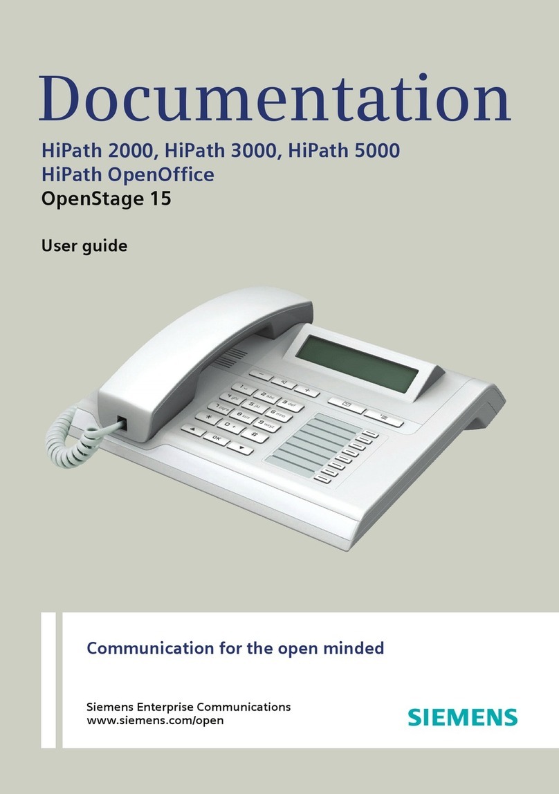
Avaya IP Office Small Office Edition User manual

IP Office - Small Office Edition
Installation Manual
40DHB0002UKED – Issue 2 (29t
h
July 2004

Page 2 - Contents
Introduction...................................................................................................................... 4
Contents
General............................................................................................................................................ 4
Scope of Manual ............................................................................................................................. 4
The IP Office - Small Office Edition Platform................................................................ 5
General............................................................................................................................................ 5
Power Fail .............................................................................................................................................................5
Avaya IP Office - Small Office Edition (Front View) ........................................................................ 6
Port connections ...................................................................................................................................................6
Avaya IP Office - Small Office Edition (Rear View)......................................................................... 7
Port connections ...................................................................................................................................................7
Typical Configurations..................................................................................................................... 8
Home Based Business..........................................................................................................................................8
Single Site Business .............................................................................................................................................9
Multi-site Business ..............................................................................................................................................10
Country Variants............................................................................................................ 11
Avaya IP Office - Small Office Edition Systems ............................................................................ 11
Trunk Module Kits ......................................................................................................................... 11
Power Supplies ............................................................................................................................. 12
Avaya IP Office - Small Office Edition PCMCIA Cards ................................................................. 12
Avaya IP Office - Small Office Edition Applications ...................................................................... 13
Preparing for Installation.............................................................................................. 14
Introduction.................................................................................................................................... 14
Tools & Parts Required ................................................................................................................. 14
Space requirements ...................................................................................................................... 14
Environmental requirements ......................................................................................................... 15
Power Supply Requirements......................................................................................................... 15
Functional Ground......................................................................................................................... 16
Out of Building Telephone Installations.........................................................................................17
Installing a New System ............................................................................................... 18
Unpacking...................................................................................................................................... 18
Initial Assembly - Overview ........................................................................................................... 18
Avaya IP Office - Small Office Edition Shelf/Wall Mounting.......................................................... 19
Installation of Integral Modules ..................................................................................................... 20
Basic System Programming......................................................................................... 21
Introduction.................................................................................................................................... 21
Programming Tools ....................................................................................................................... 21
PC to Avaya IP Office - Small Office Edition LAN Port Connection ...................................................................21
Initial Programming ....................................................................................................................... 22
Telephone Installation .................................................................................................. 24
Checking Telephones.................................................................................................................... 24
Connecting & Testing Avaya IP Office - Small Office Edition Telephones.........................................................24
Connecting & Checking Two-Wire Telephones..................................................................................................25
Power Fail Telephones and Sockets ..................................................................................................................25
Wall Mounting 2000 Series Telephones ....................................................................................... 26
Wall Mounting 44/4600 & 6400 Series Telephones...................................................................... 27
System Handover .......................................................................................................... 28
Checklist ........................................................................................................................................ 28
Page 2 - Contents IP Office - Small Office Edition Installation Manual
40DHB0002UKED – Issue 2 (29th July 2004

Contents - Page 3
Contents (Cont.)
Safety and Homologation Statements......................................................................... 29
Lithium Batteries............................................................................................................................ 29
Lightning Protection/Hazard Symbols ........................................................................................... 29
Electromagnetic Interference Information ..................................................................................... 30
Federal Communications Commission (FCC) ....................................................................................................30
Canadian Department of Communications (DOC) .............................................................................................30
Trunk Interface Modules................................................................................................................ 31
ROW....................................................................................................................................................................31
USA/Canada .......................................................................................................................................................31
Further Information and Product Updates..................................................................................... 31
Support Telephone Numbers..............................................................................................................................31
Regulatory Instructions for Use..................................................................................................... 32
Avaya IP Office - Small Office Edition Operation in Australia.............................................................................32
Avaya IP Office - Small Office Edition Operation in Canada ..............................................................................32
Avaya IP Office - Small Office Edition Operation in EU......................................................................................33
Avaya IP Office - Small Office Edition Operation in New Zealand .....................................................................33
Avaya IP Office - Small Office Edition Operation in USA ...................................................................................33
Technical Data ............................................................................................................... 34
Port Pinouts ................................................................................................................................... 34
Analog Trunk Ports (RJ45) .................................................................................................................................34
Power Fail and POT Ports (RJ45) ......................................................................................................................34
DS/DT Ports (RJ45) ............................................................................................................................................34
ISDN Port – BRI (RJ45) ......................................................................................................................................34
ISDN Port – PRI (RJ45) ......................................................................................................................................35
WAN/LAN Port – 10/100 BaseT..........................................................................................................................35
DTE Port (9 Way D-Type socket) .......................................................................................................................35
Audio Port (3.5mm Stereo Jack Socket).............................................................................................................35
Functional Ground (3.5mm Jack Socket) ...........................................................................................................35
External Control Port (3.5mm Stereo Jack Socket) ............................................................................................36
WAN Port (37 Way D-Type Socket)....................................................................................................................36
Cables ........................................................................................................................................... 37
DTE Cable...........................................................................................................................................................37
DT Line Cord for Structured Cabling ..................................................................................................................38
PRI/BRI ISDN Cable ...........................................................................................................................................39
LAN Interconnect Cable......................................................................................................................................40
LAN Cable...........................................................................................................................................................41
X.21 WAN Cable .................................................................................................................................................42
V.35 WAN Cable .................................................................................................................................................43
Telephone Converter Cables ..............................................................................................................................44
Port Safety Classification .............................................................................................................. 45
Compliance with FCC Rules ...............................................................................................................................45
Technical Specifications................................................................................................................ 46
General ...............................................................................................................................................................46
Interfaces ............................................................................................................................................................46
Protocols .............................................................................................................................................................47
SNMP Functionality.............................................................................................................................................48
SNMP Agent Configuration.................................................................................................................................48
MIBs Supported ..................................................................................................................................................48
Trap Generation ..................................................................................................................................................49
MIB Loading ........................................................................................................................................................49
CastleRock SNMPc 5.1.6c and earlier: ..............................................................................................................50
HP OpenView Network Node Manager 6.41 and earlier: ...................................................................................50
Index ............................................................................................................................... 51
IP Office - Small Office Edition Installation Manual Introduction - Page 3
40DHB0002UKED – Issue 2 (29th July 2004 General

Introduction General - Page 4
Introduction
General
This manual covers the installation of Avaya IP Office - Small Office Edition equipped with
release Level 2.0+ software. It is intended for use by installers and maintainers who have
successfully completed the appropriate Avaya IP Office - Small Office Edition training
courses.
Ensure that you have read and understood this manual before beginning installation.
Scope of Manual
This manual, for the Avaya IP Office - Small Office Edition systems, covers the following
subjects and should be read in the sequence shown below:
– Avaya IP Office - Small Office Edition Platforms :
This section provides details of the various Avaya IP Office - Small Office Edition
platforms available. Illustrations of the front and rear of the unit show what
ports/sockets/etc are provided. Typical configuration examples are also provided in this
section. A further section details the country variants of modules/trunks/integral
modules/etc.
– Preparing for and Installing a new system :
These sections provide all the information required and the actions to be performed to
physically install a IP Office - Small Office Edition, i.e. what tools are required, the
environmental/power requirements, wall mounting, etc. The software installation is
covered in the following section.
– Basic System Programming :
System programming is necessary for configuration and maintenance of the Avaya IP
Office - Small Office Edition. This manual only covers the installation of the IP Office -
Small Office Edition suite of programs (see page 21). For full details refer to the
Installation Wizard Help files and/or to the Manuals contained on the documentation
CD (supplied with every unit).
– Terminal/Telephone Installation :
This manual details the information required to install telephones but does not detail
the usage and functionality of IP Office - Small Office Edition terminals/telephones.
These details are to be found in the appropriate User Guides.
The terminals/telephones that are supported by the IP Office - Small Office Edition are
(these are also used across a number of Avaya platforms):
Avaya 2000 Series 20AT, 20CC, 2010, 2030, 2050, 20DSS/BLF and 20DT
Avaya 2400 Series 2402, 2410 and 2420
Avaya 3600 Series 3616, 3626
Avaya 4400 Series 4406D, 4412D, 4424D and 4450DSS*
Avaya 4600 Series 4601, 4610, 4602, 4602SW, 4620, 4606, 4612 and 4624
Avaya 5400 Series 5402, 5410
Avaya 5600 Series 5601, 5610
Avaya 6400 Series 6408D+, 6416D+M, 6424D+M and XM24(DSS)
*Caution: See page 38 for wiring details on a 4450DSS module.
– Safety and Homologation Statements :
This provides all the necessary Safety, Homologation Statements and Regulatory
Instructions for Use required. This section also detail where further information,
including other Manuals and support telephone numbers, can be obtained.
– Technical Data :
This manual contains information on the Port Pinouts/Safety classifications, cables,
and basic technical specifications only. Descriptions of the functionality, features and
performance of the Avaya IP Office - Small Office Edition are covered by the Product
Description (see page 31).
IP Office - Small Office Edition Installation Manual Introduction - Page 4
40DHB0002UKED – Issue 2 (29th July 2004 General
The IP Office - Small Office Edition Platform General - Page 5
The IP Office - Small Office Edition Platform
General
The Avaya IP Office - Small Office Edition system platform is supplied in a number of
variants as follows:
1. Two Analog Trunks + 4 POTs (analog telephones) + 3 VoIP compressors.
2. Two Analog Trunks + 8 POTs (analog telephones) + 3 VoIP compressors.
3. Four Analog Trunks + 4 POTs (analog telephones) + 8 DS/DT + 3 VoIP compressors.
4. Four Analog Trunks + 4 POTs (analog telephones) + 8 DS/DT + 16 VoIP compressors.
See Avaya IP Office - Small Office Edition (Front View) for details and page 11 for country
specific variants.
The Avaya 4600 series telephones use the LAN ports
The analog trunks ports are designed for loop start trunks and do not support Plain
Ordinary Telephones (POTs)
The POT Ports support analog telephone and must not be connected to trunks.
The DT ports support Avaya 2000 series telephones and the DS ports support Avaya
6400 and/or Avaya 4400 series telephones.
Both ports can be set for either µ-Law or A-Law PCM encoding. At default DT ports are
set to A-Law and DS ports are set to µ-Law. However, these can be switched in software
(refer to the Administration Manager Manual for details).
All variants have a WAN port presented as 10/100 Ethernet port, and four LAN
10/100Mbps auto MD1/MD1X switch ports.
In addition the Avaya IP Office - Small Office Edition can be fitted with the following
optional modules:
• Trunk Interfaces
These can be either a single PRI T1 (23B+1D or 24B trunks) or Quad BRI (8 trunks)
and are supplied as trunk module kits.
• WAN Port
This port supports a single synchronous data connection for X.21/V.24\V.35. The WAN
kit is supplied with the WAN module and a replacement rear panel.
• Wireless LAN card
This is a wireless network card with integrated radio modules and antennas (2.4GHz).
The card supports IEEE 802.11b and WiFi standards.
• Voice Memory card
Provides memory capacity for embedded voice mail and auto attendant features.
See page 20 for expansion and page 11 for country specific variants.
Power Fail
If the mains power supply fails Analog Port 2 is automatically switched to POT Port 2.
IP Office - Small Office Edition Installation Manual The IP Office - Small Office Edition Platform - Page 5
40DHB0002UKED – Issue 2 (29th July 2004 General

Page 6 - Avaya IP Office - Small Office Edition (Front View) The IP Office - Small Office Edition Platform
Avaya IP Office - Small Office Edition (Front View)
Analog Trunk Ports 1 - 4
(at default Line Nos. 1 - 4,
loop Start, DTMF dialing)
DS Ports 1- 8
(at default Extn. Nos. 205 - 212)
Green LEDs – Terminal connected
Yellow LEDs – Status of WAN links
Unit Status LED
Red – Alive but not initiated
Green – Running O
K
Phone Ports (POTs) 1 - 4
(at default Extn. Nos. 201 - 204)
Left hand LEDs 1 - 4 = ISDN 1 - 4 status
Right hand LED 4 = WAN status
LAN Port Switch
(at default LAN Port 14)
Solid green LEDs – LAN OK
Flashing green – LAN OK and active
Yellow LED on – 100Mbs full duplex
WAN Por
t
Ethernet LAN Por
t
(at default LAN Port 2
)
Note: A fully equipped version of the Avaya IP Office - Small Office Edition is shown
above. A DT port variant is also available. Two other variants are available; one
with DS1-4 ports allocated to POT ports 5-8 and DS5-8 not fitted. The other
variant does not have the top row of RJ45 ports fitted (see page 11 for country
variants).
Port connections
• DT/DS Ports: DT ports are used for connection to Avaya 2000 series telephones
(see page 4) DS ports support Avaya 6400 and/or Avaya 4400 series telephones.
Both variants support either A-Law or µ-Law PCM encoding (default is country
dependant and can be switched in software). Using DT Line Cords (see page 38)
and standard structured wiring, these RJ45 ports can be extended to the required
telephone location. When telephones are equipped with line cords that terminate in
RJ11 plugs, then pin-to-pin RJ11/RJ45 adapters should be used.
• Analog Trunk Ports: These ports are used for connection to standard analog
trunks (loop start). Using standard structured wiring, these RJ45 ports can be
extended to the required trunk sockets. In the event of mains power supply failure
Analog Port 2 is automatically switched to POT port 1.
• Plain Ordinary Telephone (POT) Ports: These ports are used for connection to
standard analog telephones, fax machines and modems. Using standard structured
wiring, these RJ45 ports can be extended to the required telephone location. When
telephones are equipped with line cords that terminate in RJ11 plugs, then pin-to-pin
RJ11/RJ45 adapters should be used.
• LAN Ports: These are LAN 10/100Mbps Layer 2 Ethernet switches and are used for
PC and server connectivity. They have Auto MD1/MD1X capability and hence avoid
the need for LAN crossover cables when connecting to a hub. They can also be
used to connect to IP telephones (Avaya 4600 IP series). LAN ports allow
information relating to incoming and outgoing telephone calls to be forwarded to PC
based applications. They also provide access to the router
functionality/configuration of the Avaya IP Office - Small Office Edition platform for
both data and Voice over IP (VoIP) calls.
• WAN Port: This is a 10/100Mbs Ethernet LAN port for connection to a WAN (e.g.
DSL).
Cables
Avaya IP Office - Small Office Edition is supplied with one red CAT 5E cable. For Port
Pinouts and Cables, refer to pages 34 and 37 respectively.
Page 6 - The IP Office - Small Office Edition Platform IP Office - Small Office Edition Installation Manual
Avaya IP Office - Small Office Edition (Front View) 40DHB0002UKED – Issue 2 (29th July 2004

The IP Office - Small Office Edition Platform Avaya IP Office - Small Office Edition (Rear View) - Page 7
Avaya IP Office - Small Office Edition (Rear View)
Port connections
• External O/P Socket: Allows externally powered circuits to be controlled via a
single 3.5mm stereo jack socket.
• DC Power I/P Socket: Socket for the external 24V DC unregulated power supply
(supplied with kit).
• DTE Port: A 9-way D-type socket. Used for applications Licence Key device
(Dongle) and connection to PCs, Servers and EFTPOS terminals.
• Trunk Ports: These can be either a single PRI T1 (23B+1D or 24B trunks) or Quad
BRI (8 trunks). See page 20 for expansion and page 11 for country specific variants.
• WAN Port: This port supports a single synchronous data connection, for
X.21/V.24/V.35 interfaces. The selection of the required interface is automatically
determined from the pin-out of the cable plugged into the ‘WAN’ port. This cable
must be connected before power is applied for auto detection to work. Connection
to a Digital Leased Circuit is made by connecting the WAN port on the rear of the
unit to the existing Network Terminating Unit (NTU) via the appropriate X.21, V.35 or
V.24 cable. See pages 42 and 43 for cable details and page 36 for port details.
• PCMCIA slots: Used for optional Avaya supplied wireless LAN and/or additional
Voice Memory cards.
• Audio I/P Socket: A single 3.5mm stereo or mono jack socket that enables input
from an external 'Music-on-Hold' source.
• Functional Earth Socket: A single 3.5mm jack socket with all 3 pins connected to
ground. For use in areas with high lightning and/or ESD. Connect a 3.5mm jack plug
(not supplied), fitted with a green sleave 14swg wire, to the buildings approved earth
point (must conform to local grounding (earthing) regulations).
CAUTION: This is not a protective ground point.
The unit is also earthed via the power cable (through the lump in line PSU).
Port Pinouts and Cables
For Port Pinouts and Cables, refer to pages 34 and 37 respectively.
IP Office - Small Office Edition Installation Manual The IP Office - Small Office Edition Platform - Page 7
40DHB0002UKED – Issue 2 (29th July 2004 Avaya IP Office - Small Office Edition (Rear View)

Page 8 - Typical Configurations The IP Office - Small Office Edition Platform
Typical Configurations
The following paragraphs illustrate three typical scenarios for Avaya IP Office - Small
Office Edition. These are configuration examples only and are intended to demonstrate
the flexibility of the Avaya IP Office - Small Office Edition.
Home Based Business
A small home based business that requires the following connectivity:
• One Exchange Line (ADSL enabled)
• One broadband Internet connection
• Up to four analogue telephones (POTs)
• PC based softphones
• One Fax
• One printer
• Enhanced onboard Voicemail
• One Laptop PC
• One PC
Avaya Kit List
Avaya IP Office - Small Office Edition 2T +4A (3 VoIP)
Country specific power lead (must be sourced separately)
Analogue telephones (can be sourced separately)
Phone Manager Lite (with an optional upgrade to Phone Manager Pro)
Serial Port Dongle (for Licence keys) fitted to rear of unit
Licences for Wireless Access Point, VPN and IP Softphone
On board Voicemail 64M Memory card (fitted to rear of unit)
Wireless LAN card (802.11b) fitted to rear of unit
LAN access to Internet
Analog
Trunk Line
Wireless
Access
Laptop PC
(Softphone)
FAX
Extension 204
Printer
Desktop PCs
(with Softphones)
ADSL
Router
S
P
L
I
T
T
E
R
Exchange
Line
Extension 203
Extension 202
Extension 201
Page 8 - The IP Office - Small Office Edition Platform IP Office - Small Office Edition Installation Manual
Typical Configurations 40DHB0002UKED – Issue 2 (29th July 2004

The IP Office - Small Office Edition Platform Typical Configurations - Page 9
Single Site Business
A single site small business that requires:
• Three Exchange Lines (one ADSL enabled)
• One broadband Internet connection
• Up to six analogue telephones (POTs)
• One Fax
• One printer
• Enhanced onboard Voicemail
• Three company PCs
• Door entry security
Kit List
Avaya IP Office - Small Office Edition 4T +8A (3 VoIP)
Country specific power lead (must be sourced separately)
Analogue telephones (can be sourced separately)
Phone Manager Lite x 5
Serial Port Licence Key device (Dongle) fitted to rear of unit
Licences for Wireless Access Point, VPN and IP Softphone
On board Voicemail 64M Memory card (fitted to rear of unit)
Connection from Ext O/P for door relay (fitted to rear of unit)
LAN access to Internet
Analog Trunk Lines
FAX
Extension 208
Printer
Desktop PCs
ADSL
Router
S
P
L
I
T
T
E
R
Exchange
Lines
Extension 202
Extension 205
Extension 201
Extension 204
Extension 203
IP Office - Small Office Edition Installation Manual The IP Office - Small Office Edition Platform - Page 9
40DHB0002UKED – Issue 2 (29th July 2004 Typical Configurations

Page 10 - Typical Configurations The IP Office - Small Office Edition Platform
Multi-site Business
A multi-site business that requires:
• Two Exchange Lines (one ADSL enabled)
• Two Digital Exchange Lines (ISDN enabled)
• One broadband Internet connection
• Auto Answering
• PC based Softphones
• Up to eight digital telephones
• Two Faxes and two Printers
• Enhanced Voicemail
• Six company PCs with Softphone capabilities
• Door entry security
Kit List
Avaya IP Office - Small Office Edition 4T +8A +8DS (16 VoIP)
Country specific power lead (must be sourced separately)
Avaya digital telephones
Phone Manager Lite x 5
Serial Port Licence Key device (Dongle) fitted to rear of unit
Licences for VMPro with Auto Attendant and IP Softphone
On board Voicemail 64M Memory card (fitted to rear of unit)
Connection from Ext O/P for door relay (fitted to rear of unit)
Third party LAN switch
LAN access
to Interne
t
Analog Trunk Lines FAXes
Extensions
201 & 202
ADSL
Router
S
P
L
I
T
T
E
R
Exchange
Lines
Extension 208
Extension 212
Extension 206
Extension 205
Extension 207
Extension 2010
Extension 211
Extension 209
Two ISDN Lines
to Quad BRI
on rear of uni
t
A
pplications
Server
Printers
1 & 2
PCs 1 to 6
(with SoftPhones)
LAN Switch
Page 10 - The IP Office - Small Office Edition Platform IP Office - Small Office Edition Installation Manual
Typical Configurations 40DHB0002UKED – Issue 2 (29th July 2004

Country Variants Avaya IP Office - Small Office Edition Systems - Page 11
Country Variants
The following are lists of the country variants for each Avaya IP Office - Small Office
Edition platform, trunk module kits, Integral module kits and expansion modules. The PCS
level for each module can be found on a label that is stuck to the base of each module.
Avaya IP Office - Small Office Edition Systems
Throughout this section the following abbreviations are used:
ALL = Global
ROW = Rest of world (excluding USA, Canada)
NA = North America (USA and/or Canada)
CALA = Caribbean/Latin America
CH = China
EU = Europe
KR = Korea
NZ = New Zealand
For countries outside North America/ CALA, use ROW variant unless stated otherwise.
IP Office - Small Office Edition Variants
Variant Country SAP Code
IP Office - Small Office Edition 2T + 4A (3 VoIP) US 700280167
IP Office - Small Office Edition 2T + 4A (3 VoIP) ROW 700280175
IP Office - Small Office Edition 4T + 8A (3 VoIP) US 700293053
IP Office - Small Office Edition 4T + 8A (3 VoIP) ROW 700293061
IP Office - Small Office Edition 4T + 4A + 8DS (3 VoIP) US 700280183
IP Office - Small Office Edition 4T + 4A + 8DS (16 VoIP) US 700280191
IP Office - Small Office Edition 4T + 4A + 8DS (3 VoIP) ROW 700280209
IP Office - Small Office Edition 4T + 4A + 8DS (16 VoIP) ROW 700280217
IP Office - Small Office Edition 4T + 4A + 8DT (3 VoIP) ROW 700280225
IP Office - Small Office Edition 4T + 4A + 8DT (16 VoIP) ROW 700280233
Key: 2T or 4T etc. = number of analog trunks
+4 or +8 = number of POT ports
+8DT or +8DS = number of Digital Station or Digital Terminal ports
(3VoIP) = number of VoIP CODECs (COder DECoder)
Trunk Module Kits
BRI Trunk Interface Module
Variant Country SAP Code
BRI 8 (UNI) expansion kit ROW 700262017
PRI Module
Variant Country SAP Code
PRI 24 T1 Expansion Kit NA 700185200
WAN Module
Variant Country SAP Code
WAN Expansion Kit ALL 700289713
Notes: 1. For countries outside North America/CALA, use the ROW variant unless
stated otherwise.
2. PRI T1trunks support both ISDN and Analog emulation. The default setting is
23B+1D and is switchable in the installation software to become a 24B trunk.
IP Office - Small Office Edition Installation Manual Country Variants - Page 11
40DHB0002UKED – Issue 2 (29th July 2004 Avaya IP Office - Small Office Edition Systems

Page 12 - Power Supplies Country Variants
Power Supplies
Common Lump-in-Line Power Supply units are supplied with each Avaya IP Office - Small
Office Edition. However, the power leads are county specific and must be ordered
separately. These power leads are 3-pined earthed and can only be used on Small
Office Edition systems. The part numbers are as follows:-
Variant Country SAP Code
IP Office - Power Lead (earthed) UK 700289747
IP Office - Power Lead (earthed) EU CEE7/7 700289762
IP Office - Power Lead (earthed) US 700289770
IP Office - Power (earthed) Lead Pack 10 UK 181567
IP Office - Power Lead (earthed) Pack 10 US 181568
IP Office - Power Lead (earthed) Pack 10 EU CEE7/7 181569
IP Office - Power Lead (earthed) China 700261977
IP Office - Power Lead (earthed) Pack 10 China 182196
Avaya IP Office - Small Office Edition PCMCIA Cards
The slots on the rear of the product can accommodate one or both of the following
options:
Variant Country SAP Code
64m Memory card (Voice Mail) ALL 700289721
Wireless LAN card ALL 700289739
Page 12 - Country Variants IP Office - Small Office Edition Installation Manual
Power Supplies 40DHB0002UKED – Issue 2 (29th July 2004

Country Variants Avaya IP Office - Small Office Edition Applications - Page 13
Avaya IP Office - Small Office Edition Applications
As part of the IP Office Family, the Small Office Edition supports a broad range of optional
feature enhancements and applications. The following list is a summary of options that are
considered to be most relevant for use in the small business environment, as targeted by
this product. For an exhaustive list of all supported options and license upgrades, please
refer to the applications documentation for IP Office and the relevant regional price lists.
Description Function SAP Code
License Key Devices (Dongles)
Feature Key - Serial Port (9-pin) Device for direct attachment to Small Office Edition (required for
Remote Feature Activation)
700293095
Feature Key - Parallel Port Device for attachment to applications server (required for
Remote Feature Activation)
700185234
Feature Key - USB Port Device for attachment to applications server (required for
Remote Feature Activation)
700261506
Client Software
Phone Manager Lite
Standard CTI desktop application for client PCs (call history,
directory, speed dials) - all users included
Phone Manager Pro RFA 5 Enhanced CTI desktop application for client PCs (VM control,
queuing, CRM screen pops) - 5 users 177469
IPPro RFA 5 Adds IP softphone functionality to Phone Manager Pro - 5 users 174463
IP Endpoint RFA 5 Enables support of 3rd party IP end-points (including wireless
VoIP) - 5 users 174957
Personal Numbering RFA Enables enhanced personal numbering 181572
CTI DECT RFA 8 Enables DECT feature integration (RoW only) - 8 handsets 171989
Messaging Software
VoiceMail Lite 4-port standard voicemail PC application included
Voice Memory Card 3-port on-board voicemail/auto-attendant application (no PC
required) 700289721
VoiceMail Pro RFA 4-port advanced voicemail PC application (incl: GUI, AA,
queuing, call recording) 171991
Audix RFA Enables use of Intuity Audix as Centralised Voice Mail. (does not
require VoiceMail Pro) 177467
VPIM RFA Enables use of networked Audix/3rd party centralized voicemail 181570
Integrated Messaging Pro RFA Enables synchronization to MS email systems. GUI to control
voicemails within Outlook (requires VoiceMail Pro). 171990
Avaya Text-to-Speech RFA Enables text to speech for messaging applications 181573
3rd party IVR RFA Enables use of 3rd party Interactive Voice Response systems 181571
System Software
SoftConsole RFA Enables PC-based system console (including BLF) 171987
CBC RFA Enables real-time & historical summary reports on system &
departmental call handling 171993
Access Point RFA Enables wireless access point functionality (requires Wireless
LAN card 700289739 to be installed) 182197
IPSEC VPN RFA Enables secure VPN tunnels with encryption 181575
MS-CRM RFA Enables integration with Microsoft CRM Professional (phase 1 -
incl: Screen Pop and Auto-Dial) 180588
N.B. Only DECT and MS-CRM are region specific. All other options are global
IP Office - Small Office Edition Installation Manual Country Variants - Page 13
40DHB0002UKED – Issue 2 (29th July 2004 Avaya IP Office - Small Office Edition Applications

Page 14 - Introduction Preparing for Installation
Preparing for Installation
Introduction
This section reviews the requirements for installing an Avaya IP Office - Small Office
Edition system. You must meet these requirements for the system to operate safely and in
the intended manner.
This section covers :
– Tools & Parts Required on page 14.
– Space requirements on page 14
– Environmental requirements on page 15.
– Power Supply Requirements on page 15.
Tools & Parts Required
General :
– Pozidrive No. 1 screwdriver for removal of unit covers.
– Cutter/knife for cable ties.
– Cable ties
– Pozidrive No. 4 screwdriver for Analog Trunk 16 expansion module grounding post.
Note: In addition, ensure that you have sufficient cables that are not supplied with
the modules, e.g. Line Cords for structured cabling (see page 37) and power
supply cables (see page 12).
Programming :
These are the tools required for programming of a newly installed Avaya IP Office - Small
Office Edition system.
– PC running Windows 98/2000/ME/XP or NT with the following specification:
Intel Pentium ll 333Mhz or faster, 100MB HD space, CD-ROM drive, COM port,
terminal emulation (e.g. HyperTerminal) and a super VGA Monitor (set to 1024 by 768).
– PC with a LAN card with either a fixed IP address (allocated by your system
administrator) or be using DHCP to obtain an IP address.
– IP Cat. 5E patch cable (red – supplied with system see page 39).
– Small Office Edition Administration CD (1 of 3 - supplied with system).
– Small Office Edition User CD (2 of 3 - supplied with system).
– Small Office Edition Documentation CD (3 of 3 - supplied with system).
– Small Office Edition Manager Application Manual (supplied on CD1 with system).
– Small Office Edition Feature Key device (Dongle) that is required where software that
requires a Licence Key is to be installed).
Space requirements
Check that the planned location meets the following requirements.
Height : 76mm (3 inches)
Width : 255mm (10 inches)
Depth : 235mm (9.3 inches)
• Where an Avaya Small offices is free standing, allow a minimum clearance of 62mm
(2.5 inches) either side for cable trunking.
• Check there is suitable lighting for installation, system programming and future
maintenance.
• Check that there is sufficient working space for installation and future maintenance.
• Ensure that likely activities near the system will not cause any problems, e.g. access to
and maintenance of any other equipment in the area.
Page 14 - Preparing for Installation IP Office - Small Office Edition Installation Manual
Introduction 40DHB0002UKED – Issue 2 (29th July 2004

Preparing for Installation Environmental requirements - Page 15
Environmental requirements
The planned location must meet the following requirements:
– Check that the area is a well ventilated area, having a temperature range of 0°C to
+40°C and a humidity range of 10% to 95% non-condensing.
– Check there are no flammable materials in the area.
– Check there is no possibility of flooding.
– Check that no other machinery or equipment needs to be moved first.
– Check that it is not an excessively dusty atmosphere.
– Check that the area is unlikely to suffer rapid changes in temperature and humidity.
– Check for the proximity of strong magnetic fields, sources of radio frequency and other
electrical interference.
– Check there are no corrosive chemicals or gasses.
– Check there is no excessive vibration or potential of excessive vibration, especially of
the cabinet mounting surface.
– Check that, for the USA only, where telephones are installed in another building, that
the appropriate IROB protectors are fitted (see page Error! Bookmark not defined.).
IMPORTANT SAFETY INSTRUCTIONS
When using your telephone equipment, basic safety precautions should always be
followed to reduce the risk of fire, electric shock and injury to persons, including the
following:
1. Do not use this product near water, for example, near a bath tub, wash bowl, kitchen
sink or laundry tub, in a wet basement or near a swimming pool.
2. Avoid using a telephone (other than a cordless type) during an electrical storm. There
may be a remote risk of electric shock from lightning.
3. Do not use the telephone to report a gas leak in the vicinity of the leak.
4. Use only the power cord and batteries indicated in this manual. Do not dispose of
batteries in a fire. They may explode. Check with local codes for possible special
disposal instructions.
SAVE THESE INSTRUCTIONS.
Power Supply Requirements
Avaya IP Office - Small Office Edition should only be connected to a clean power supply
or to a UPS with 3-pin connectors including earth.
CAUTION: The Lump-in-Line PSUs supplied with each Avaya IP Office - Small Office
Edition module must only be connected to a 50/60Hz, 100-240V power
source.
– UPS Equipment :
The use of UPSs to support the Avaya IP Office - Small Office Edition system during
mains power failure is highly recommended. Such equipment also provides mains
conditioning. Contact Avaya for details of preferred and tested suppliers and models.
IP Office - Small Office Edition Installation Manual Preparing for Installation - Page 15
40DHB0002UKED – Issue 2 (29th July 2004 Environmental requirements

Page 16 - Functional Ground Preparing for Installation
Functional Ground
The IP Small Office Edition Office functional grounding is as follows:
Caution: This functional ground is not a protective ground.
To connect the functional ground:
1. Use a 3.5mm Jack Plug (not supplied with kit) fitted with a suitable length of #14
AWG (minimum) solid insulated cable. The sleeve must not be green/yellow.
2. Insert this Jack Plug into the Functional Ground Jack Socket.
3. Connect, using a fastening that satisfies local regulations, the other end of the #14
AWG wire to the approved ground, such as building steel or an earthed metal cold
water pipe.
Page 16 - Preparing for Installation IP Office - Small Office Edition Installation Manual
Functional Ground 40DHB0002UKED – Issue 2 (29th July 2004

Preparing for Installation Out of Building Telephone Installations - Page 17
Out of Building Telephone Installations
Installation of telephones that are external to the building housing the Avaya IP Small
Office Edition or in another building require In-Range-Out-Of-Building (IROB) protectors to
protect the control unit and device from electrical surges. Only Digital Stations should be
used for out of building/external telephones. Two IROB protectors are required.
The following diagram provides an overview of the protection requirements for installation
of telephones that are external to the building housing the Avaya IP Office. Details of
these requirements are given in the following paragraphs:
A Primary Protection Box must be provided at the point where the cable enters the
building. This should be three-point protection (tip, ring and ground). Typically this would
be gas tube protection provided by the local telephone company. The ground wire must
be thick enough to handle all the lines being affected by indirect strike at the same time.
CAUTION: All cabling between buildings must not be exposed. E.g. cabling between
buildings must be carried in suitably earthed ducting; ideally underground.
The following IROBs must be used:
146E - TDL - SAP code 407568161
Installation of a Contact Closure Adjunct controlled device outside the building requires a
146G Surge Protector – SCL/8 to protect the control unit from electrical surges.
IROB Installation
Install the 146E IROBs as per the instructions supplied with the IROB. Typically this would
be as follows:
IP Office - Small Office Edition Installation Manual Preparing for Installation - Page 17
40DHB0002UKED – Issue 2 (29th July 2004 Out of Building Telephone Installations

Page 18 - Unpacking Installing a New System
Installing a New System
Unpacking
Before proceeding with installation, ensure that you have read the notes covered in
Preparing for Installation on page 14.
Unpacking and checking :
1. Before unpacking check for any signs of damage that has occurred during transit.
If any damage exists bring it to the attention of the carrier.
2. Check all cartons against the packing slip (see page 11).
Report any errors or omissions to the equipment supplier.
3. While unpacking the equipment, retain all the packaging material.
Fault returns are accepted only if repackaged in the original packaging.
4. Visually inspect each item and check that all the necessary documentation and
accessory items have been included. Report any errors or omissions to the dealer who
supplied the equipment.
5. Ensure you read and understand any documentation included with any item.
Initial Assembly - Overview
Prior to initial assembly and mounting (rack or free standing) of your system, check that:
• The required Trunk Interface Modules have been installed (see page 20) and are of the
correct country variant type (see page 11).
• Where structured cabling is to be used it has been installed, conforms to all local
regulations and is clearly labeled.
Perform the following:
1. Mount the Avaya IP Office - Small Office Edition module in its final location.
2. Run the Lump-in-Line PSU cable back to the switchable mains supply but do not
switch-on or connect the PSU to the Avaya IP Office - Small Office Edition.
4. Connect the Trunks, using PRI/BRI ISDN Cables (see page 39), to your provider's
trunk sockets.
5. Connect the DT/DS/POT Ports, using DT Line Cords (see page 38), to the structured
cable sockets or directly to the appropriate telephone (see page 24). Note that in
default, the lowest port number corresponds to the lowest extension number (201).
6. Install all telephones in their appropriate locations.
For wall mounting, see pages 26 and 27.
7. Connect your PC LAN Port to one of the LAN Ports on the front of an Avaya IP Office -
Small Office Edition using a LAN Cable (see page 41).
8. Switch on the ac mains supply.
9. From the Administrator CD (see page 21), install on your PC the software required to
configure and manage your Avaya IP Office - Small Office Edition (see page 21).
Page 18 - Installing a New System IP Office - Small Office Edition Installation Manual
Unpacking 40DHB0002UKED – Issue 2 (29th July 2004

Installing a New System Avaya IP Office - Small Office Edition Shelf/Wall Mounting - Page 19
Avaya IP Office - Small Office Edition Shelf/Wall Mounting
All variants of the Avaya IP Office - Small Office Edition can be either shelf or wall
mounted. Four retaining slots (item below) enable the IP Office - Small Office Edition
unit to be mounted and secured either:
• Horizontally on a shelf - leaving sufficient space for the cabling at both front and rear of
the unit.
• Vertically from a wall – with the front panel facing down only.
A Z-bracket (item below, supplied with unit) is used to retain the Small unit in
position.
Cautions: 1. The Z-bracket must not be used as the sole mounting fixture.
2. When mounting vertically, the weight of the Small unit must be held by the
two No. 8 Panhead screws located into the retaining slots.
3. When mounted vertically, the air vents (on the rear panel of the IP Office -
Small Office Edition) must be on the top surface. E.g. item below must
be fitted above the unit.
Procedure:
1. Drill two holes 16cm apart (horizontally or vertically – see Caution 3 above).
Using suitable wall fixings (wall plugs), insert two No.8, Panhead screws (25mm long
min. - not supplied) into wall leaving approximately 1cm proud of wall.
2. Fit the Z-bracket (item below) onto the base of the unit using the M3 Plastite self
tapping screw supplied.
3. Slide the Avaya IP Office - Small Office Edition unit onto the two screws, locating them
into the two retaining slots (item below).
4. Mark the position of the retaining screw (No. 8 Panhead or similar – not supplied) that
is to be used through the slot of the Z-bracket .
5. Remove the unit from the wall and, using suitable wall fixings, drill a hole for the Z-
bracket retaining screw.
6. Re-position the Small compact Office unit and secure with a No. 8 Panhead (or similar)
through the slot of the Z-bracket.
IP Office - Small Office Edition Installation Manual Installing a New System - Page 19
40DHB0002UKED – Issue 2 (29th July 2004 Avaya IP Office - Small Office Edition Shelf/Wall Mounting

Page 20 - Installation of Integral Modules Installing a New System
Installation of Integral Modules
An Avaya IP Office - Small Office Edition can be fitted with a WAN module, a quad BRI
module or a PRI/T1 module. In addition, either or both the optional PCMCIA cards
(Memory and/or Wireless LAN) can be fitted.
Procedure:
1. To add either a wireless LAN or additional Memory card you do not need to de-
assemble a module, simply insert the card (item ) into either of the PCMCIA slots in
the rear panel . These slots are universal, hence the location does not matter. Only one
Memory or wireless LAN card can be fitted.
2. To add a WAN or BRI or PRI/T1 module:
Remove the top cover (item ) from the base cover by removing the four retaining
screws (two either side - items ) and proceed as follows.
3. Remove the rear panel (item ).
Only discard if a WAN module is being fitted (see step 4 below).
On the rear panel, press out all of the knock-out panels (item \) for a Quad BRI or just
the middle one for a PRI/T1.
- Plug the trunk board (item ) onto it's sockets and stand-off hex. pillars.
- Ensure that the trunk module sockets slot into the hole in the rear panel
(item \). Secure the trunk board in position and with the two snap-in spacers.
- Mount the existing rear panels if a WAN module is not being fitted.
If a WAN module is being fitted, see the next step.
4. To add a WAN module:
- Remove and discard the rear panel (item ).
- Fit the new rear panel (supplied with the WAN module and has a slot for WAN port
27-way D-type, items ).
- On the rear panel, press out all of the knock-out panels (item \)
- Mount WAN module (item ) in position and secure with the two snap-in spacers.
Caution: While installing modules, ensure that you wear aground wrist strap that is
connected to a suitable grounding point.
Page 20 - Installing a New System IP Office - Small Office Edition Installation Manual
Installation of Integral Modules 40DHB0002UKED – Issue 2 (29th July 2004
Table of contents
Other Avaya Office Equipment manuals
Popular Office Equipment manuals by other brands

Ericsson
Ericsson ACD Agent user guide

Jason.L
Jason.L Quadro A leg 2 person corner workstations U... Assembly instructions

Fromm&Starck
Fromm&Starck DESK DIVIDER STAR DD 03 user manual

3-form
3-form Divy SimpleSpec 200.51 installation manual

Reiner
Reiner DN41A operating instructions

Steelcase
Steelcase Brody Desk Disassembly Direction

J.Burrows
J.Burrows Stilford JBSHBB18WW Assembly instructions

Legamaster
Legamaster Glassboard 400x600 Mounting instructions

Koplus
Koplus MOUNT Assembly instructions

HeightRight
HeightRight ACTIV-Pro3 user guide

VS
VS 04423 Assembly instructions

Stealth Products
Stealth Products Simple Solutions Lexan Tray owner's manual