Avaya 1 Series User manual

Site Preparation,
Installation and Operator’s Manual
for
Avaya
Avaya Series 1
Uninterruptible Power Systems
Model 3000 VA, 200–240V
Select Code 167-405-119
Comcode 407578822

USPatents 6,069,412
5,469,098
4,980,812
Requesting a Declaration of Conformity
Units that are labeled with a CE mark comply with the following harmonized standards and EU directives:
S
Harmonized Standards: EN 50091-1-1 and EN 50091-2
S
EU Directives: 73/23/EEC, Council Directive on equipment designed for use within certain voltage limits
93/68/EEC, Amending Directive 73/23/EEC
89/336/EEC, Council Directive relating to electromagnetic compatibility
92/31/EEC, Amending Directive 89/336/EEC relating to EMC
The EC Declaration of Conformity is available upon request for products with a CE mark. For copies of the EC
Declaration of Conformity, contact:
Powerware Corporation
Koskelontie 13
FIN-02920 Espoo
Finland
Phone: +358-9-452 661
Fax: +358-9-452 665 68
Class A EMC Statements
FCCPart 15
NOTE This equipment has been tested and found to comply with the limits for a Class A digital device, pursuant to
part 15 of the FCC Rules. These limits are designed to provide reasonable protection against harmful interference when
the equipment is operated in a commercial environment. This equipment generates, uses, and can radiate radio frequency
energy and, if not installed and used in accordance with the instruction manual, may cause harmful interference to radio
communications. Operation of this equipment in a residential area is likely to cause harmful interference in which case
the user will be required to correct the interference at his own expense.
EN50091-2
Some configurations are classified under EN50091-2 as “Class-A UPS for Unrestricted Sales Distribution.” For these
configurations, the following applies:
WARNING This is a Class A-UPS Product. In a domestic environment, this product may cause radio interference, in
which case, the user may be required to take additional measures.
DEFINITY is a registered trademark of Avaya Inc.
IBM and AS/400 are registered trademarks of International Business Machines Corp.
Novell is a registered trademark of Novell, Inc.
3Com is a registered trademark of 3Com Corporation.
E
Copyright 2001 Avaya Inc. All rights reserved. No part of this document may be reproduced in any way without the
express written approval of Avaya Inc.

Site Preparation,
Installation and Operator’s Manual
for
Avaya
Avaya Series 1
Uninterruptible Power Systems
Model 3000 VA, 200–240V
Select Code 167-405-119
Comcode 407578822
Issue 6
Copyright 2001 Avaya Inc.
All Rights Reserved

Special Symbols
The following are examples of symbols used on the UPS to alert you to important information:
LOAD ON - Press the button with this symbol to energize the output receptacles
(Output On).
LOAD OFF - Press the button with this symbol to de-energize the output
receptacles (Output Off).
SAFETY EARTHING TERMINAL - Indicates the primary safety ground.
RISK OF ELECTRIC SHOCK - Indicates that a risk of electric shock is present and the
associated warning should be observed.
CAUTION: REFER TO OPERATOR’S MANUAL - Refer to your operator’s manual for
additional information.
BYPASS - Indicates bypass control switches.
INPUT BREAKER - Indicates the input breaker, which shuts off utility power to the
UPS electronics.
BATTERY BREAKER - Indicates the battery breaker, which shuts off battery power
(power transmission through the battery cord) when in the OFF (O) position.
BATTERY CONNECTOR - Indicates the battery connector, which remains
electrically “hot” even with the battery breaker off. Keep covered when not in
use.
OUTPUT BREAKER - Indicates an output breaker.

UPS WITH BDM QUICK INSTALLATION
1
Battery
Module
UPS
Module
Bypass
Distribution
Module
(BDM, 60 Hz)
2
Bypass Switch
(NORMAL Position)
3
Battery
Breaker
I
O
ON
OFF
I
O
ON
OFF
I
ON

UPS with BDM Quick Installation
4
5The UPS output voltage and the BDM input voltage is factory-configured for 208V. If you
need to change the voltages, see “UPS with Bypass Module Startup” on page 40.
6

UPS with BIM Quick Installation
UPS WITH BIM QUICK INSTALLATION
1
Bypass
Isolation
Module
(BIM 50 Hz)
Battery
Module
UPS
Module
2
Bypass Switch
(NORMAL Position)
3
Battery
Breaker
I
O
ON
OFF
I
O
ON
OFF
I
ON

UPS with BIM Quick Installation
4
5The UPS output voltage is factory-configured for 208V. If you need to change the output
voltage, see “UPS with Bypass Module Startup” on page 40.
6

i
Avaya Model 3000 UPS Operator’s Manual
S
167-405-119 Issue 6 Uncontrolled Copy
TABLE OF CONTENTS
1 Introduction 1....................................................
UPSModel and Battery Configurations 2..............................................
Load Requirements 2.........................................................
BatteryTimes for the UPS and BIM 3..............................................
BatteryTimes for the UPS with BDM 4.............................................
2 Safety Warnings 5.................................................
3 Installation 27.....................................................
Unpacking and Inspection 27.......................................................
UPSand BatteryModule Storage 27...............................................
ImportantInstallation Notes–Read Before Installing the UPS 27.............................
SystemsThat Require Contact Closure 28...........................................
SystemsThat Require a Serial Interface 28..........................................
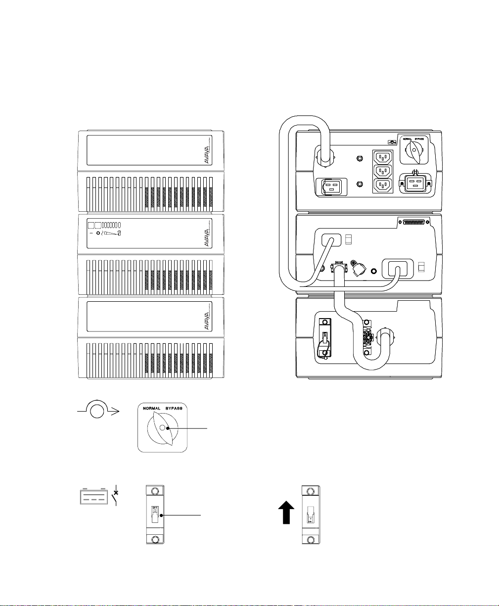
UPSwith BypassModule Installation 28...............................................
REPOInstallation 38...........................................................
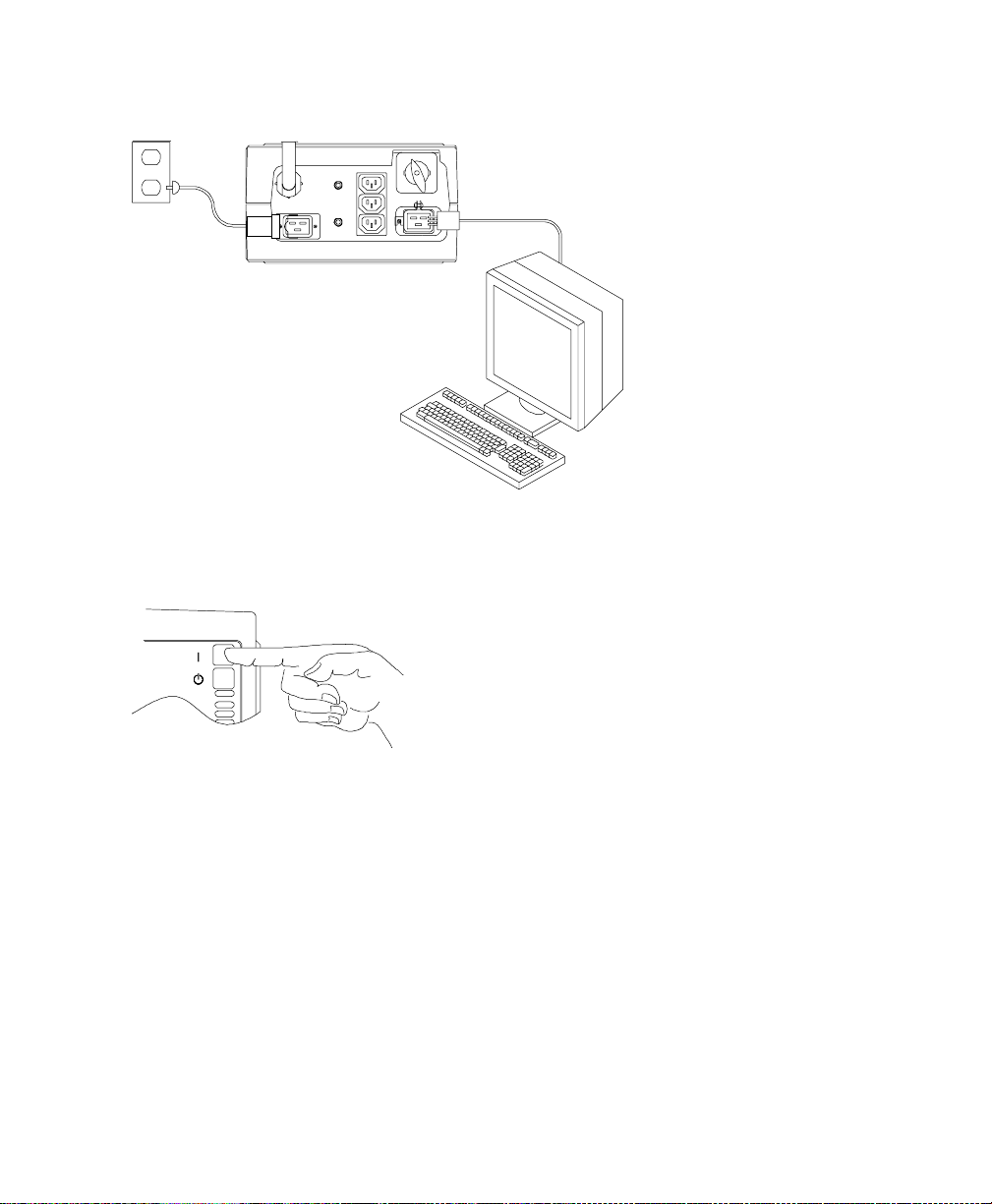
UPSwith BypassModule Startup 40...............................................
Troubleshooting Tips 42..........................................................
4 UPS Operation 43..................................................
UPS Front Panel 43..............................................................
Operating Modes 44.............................................................
NormalMode 44.............................................................
BypassMode 45.............................................................
BatteryMode 45.............................................................
Diagnostics 46.................................................................
Battery Test on Demand 46......................................................
BatteryStart 46................................................................
UPSShutdown 47...............................................................
Changing the Output Voltage 47.....................................................
Using the Bypass Module 48.......................................................
Using Maintenance Bypass 48....................................................

Table of Contents
ii Avaya Model 3000 UPS Operator’s Manual
S
167-405-119 Issue 6 Uncontrolled Copy
5 Communication 53.................................................
InitialCommunicationsSettings 53...................................................
Front PanelCommunicationsAccess 54...............................................
UPSSerialCommunicationsMenu 56.................................................
UPSCommunicationsInterface Port 59................................................
CommunicationsMode Reference Chart 61.............................................
6 Specifications 63..................................................
UPSModel 3000 Specifications 63...................................................
UPS Physical Specifications 63......................................................
Model 3000 Specificationswith the 60-Hz BDM 64.......................................
Model 3000 Specificationswith the 50-Hz BIM 64........................................
UPSTechnicalSpecifications 65.....................................................
7 Troubleshooting 67.................................................
Resetting the UPS 69............................................................
Silencing the Alarm 69...........................................................
Service and Support 69...........................................................
PartsList 70...................................................................
Index 71.........................................................

1
Avaya Model 3000 UPS Operator’s Manual
S
167-405-119 Issue 6 Uncontrolled Copy
CHAPTER 1
INTRODUCTION
Congratulations on the purchase of your Avaya Series 1 uninterruptible
power system (UPS). The Model 3000 VA UPS meets the toughest
measures of superior design and manufacturing, including ISO 9001.
You now own the most reliable power protection available.
This family of UPS models provides a steady, well-regulated power
supply for your computing and communications equipment, while
protecting it from the frequent irregularities that are inherent in
commercially available power.Voltage spikes,power surges,brownouts,
and power failures have the potential to corrupt critical data, destroy
unsaved work sessions, and in some instances, damage expensive
hardware.
Now you can safely eliminate the effects of electrical line disturbances
and guard the integrity of your systems and equipment. The Bypass
Distribution Module (BDM) and Bypass Isolation Module (BIM) have a
Maintenance Bypass feature that supplies power to your equipment even
when the UPS electronics are removed for maintenance or upgrades.
Figure 1 shows the Model 3000 UPS.
In addition, an Extended Battery Cabinet (EBC) may be configured. The
installation of this product and connection to the battery modules is
covered by a separate document shipped with the EBC.
Figure 1. Model 3000 UPS

Introduction
2Avaya Model 3000 UPS Operator’s Manual
S
167-405-119 Issue 6 Uncontrolled Copy
UPS Model and Battery Configurations
This UPS is designed to work with single-phase, three-wire, AC power
sources. There are two important considerations whenselecting theUPS
model and battery configuration to properly safeguard your equipment:
S
Load requirements
S
Battery times
Load Requirements
The load is the equipment to be protected by the UPS.Select the UPS
model that meets the power consumption requirements of the load in
volt-amperes (VA). The total load VA should not exceed the UPS VA
rating. To determine the total load requirements:
1. Obtain the load ratings from either the nameplate or operator’s
manual of the equipment to be protected by the UPS. The
ratings are listed in either watts (W), amperes or amperes
max (A), or volt-amperes.
2. If the rating is in watts, multiply by 1.4 to obtain the VA
requirement (this is the typical relationship between watts and
volt-ampere ratings in most computing equipment). However,
in some new computing equipment, the power supply is
power-factor corrected and the watts rating equals the VA
requirement. Check with the manufacturer to determine
applicability.
If the rating is in amperes or amperes max, multiply by the
input voltage to obtain the VA requirement.
3. Add all of the resultant VA ratings together to obtain the total
load requirements of the equipment to be protected (see
Figure 2). If the load consists of the power-factor corrected
supplies, it is recommended to use total watts for the load
requirements.
3 COMPUTERS 3 MONITORS EXTERNAL
MODEM
3x200WATTSx1.4=840VA 3x1AMPx240=720VA 50VA
840 VA + 720 VA + 50 VA = 1610 VA (Total Load Requirements)
200 WATTS
EACH 1AMP
EACH AT 240V 50 VA
Figure 2. Volt-Amperes Calculation Example

Introduction
3
Avaya Model 3000 UPS Operator’s Manual
S
167-405-119 Issue 6 Uncontrolled Copy
If the total load requirements of the equipment exceeds the capacity of
the UPS, you must either reduce the number of pieces of equipment, or
use a UPS with a larger load capacity.
When deciding on which pieces of equipment to remove from the UPS,
select equipment that has a lower priority for power protection.
Computers, monitors, and modems typically have a higher priority
because they could be processing or transmitting data when a power
outage occurs.
Battery Times for the UPS and BIM
During a power failure, the UPS battery supplies power to your
equipment, providing time to complete computing activities prior to
UPS shutdown. The duration of this time period is directly related to the
UPS battery configuration. By adding battery modules,you can
customize the UPS to provide enough battery time for normal
processing activities.
Load
(
VA
)
L
o
a
d
(
W
)
Average Battery Time (in Minutes)
L
o
a
d
(
V
A
)
at.7PF* Load (W) 1Module 2Modules 3Modules
600 420 36.8 88 146
800 560 27.6 66 110
1200 840 18.4 44 73
1600 1120 13.7 33 54
2000 1400 10.7 26 42
2500 1750 8.3 20 33
3000 2100 6.5 16 27
*Typical Power Factor (PF)

Introduction
4Avaya Model 3000 UPS Operator’s Manual
S
167-405-119 Issue 6 Uncontrolled Copy
Battery Times for the UPS with BDM
L
o
a
d
(
V
A
)
L
o
a
d
(
W
)
Average Battery Time (in Minutes)
Load (VA) Load (W) 1Module 2Modules 3Modules
600 402 36.8 88 146
800 533 27.6 66 110
1200 800 18.4 44 73
1600 1067 13.7 33 54
2000 1333 10.7 26 42
2500 1667 8.3 20 33
3000 2000 6.5 16 27
NOTE If using an EBC, refer to the EBCmanual for approximate batterytimes.

5
Avaya Model 3000 UPS Operator’s Manual
S
167-405-119 Issue 6 Uncontrolled Copy
CHAPTER 2
SAFETY WARNINGS
IMPORTANT SAFETY INSTRUCTIONS
SAVE THESE INSTRUCTIONS.Thismanual contains important instructionsthat you
should follow during installation of the UPS. Please read all instructionsbefore
operating the equipment and save this manualfor future reference.
DANGER
ThisUPScontainsLETHAL VOLTAGES. Allrepairs and service should be performed
byAUTHORIZED SERVICE PERSONNEL ONLY. There are NO USER
SERVICEABLE PARTSinside the UPS.
CAUTION
S
Batteriescan present a risk of electricalshockor burn from high short circuit
current.Observe proper precautions.
S
Proper disposalof batteries is required. Refer to your localcodes for disposal
requirements.
S
ThisUPS containsits own energy source (batteries).The output receptacles may
carrylive voltage even when the UPSis not connected to an AC supply.
S
Neverdisposeofbatteriesinafire.Batteriesmayexplodewhenexposedtoflame.
S
Never open or mutilate batteries. Released electrolyte is harmful to the skin and
eyes, and maybe extremely toxic.
S
Use onlythe power supplycord provided with thisUPS.The power cordis wiredin
accordance with NationalElectrical Code (NEC)specifications. Be sure the wall
outlet to be used with the UPS is wired in accordance with these same
specifications in order to avoid damage to your equipment.Be sure that
overcurrent protection for the AC outlet isprovided at the time of installation. Be
sure the input plug is completelyinserted into the walloutlet.Use asingle-phase,
three-wire,grounded AC outlet only.
S
To reduce the riskof fire or electricshock,install this UPS in a temperature and
humiditycontrolled,indoorenvironment,freeofconductivecontaminants.Ambient
temperature must not exceed 104
°
F(40
°
C).Do not operate near water or
excessive humidity (95% max).

Safety Warnings
6Avaya Model 3000 UPS Operator’s Manual
S
167-405-119 Issue 6 Uncontrolled Copy
S
Do not remove or unplug the input cord when the UPSis turned on.This removes
the safetyground from the UPS and the equipment connected to the UPS.
S
Tocomplywithinternationalstandardsandwiringregulations,thetotalequipment
connected to the output of thisUPS must not have an earth leakage current
greater than 2.75 milliamperes.
S
The walloutlet must be within 2 metersof the equipment and accessible to the
operator. The on/offswitch on the UPSdoes not electrically isolate the internal
parts.Unplug the input cord fromthe walloutlet when disconnecting the unit for
long periods of time.
S
Please note that the output socketson the UPS are electricallylive whenever the
UPSOutput On button is pressed,even if the input cord is disconnected.
S
For Bypass systems with hardwired outputs,overcurrent protection forthe output
ACcircuit(s)is to be provided byothers.
S
ForBypasssystemswithhardwiredoutputs,suitablyrateddisconnectswitchesfor
the output ACcircuit(s)are to be provided byothers.
Sikkerhedsanvisninger
VIGTIGE SIKKERHEDSANVISNINGER
GEM DISSE ANVISNINGER
DENNE BRUGERVEJLEDNING INDEHOLDER VIGTIGE
SIKKERHEDSANVISNINGER
FARE
Denne UPS indeholder LIVSFARLIG HØJSPÆNDING. Alle reparationer og
vedligeholdelse bør kun udføresaf en AUTORISERET SERVICETEKNIKER. Ingen af
UPS’ensindvendige dele kan repareres af brugeren.
ADVARSEL
S
Batterierkanudgøreenfareforelektriskstødellerforbrændingerforårsagetafhøj
kortslutningsspænding. De korrekte forholdsregler bør overholdes.
S
Korrektbortskaffelseafbatteriererpåkrævet.Overholdgældendelokalereglerfor
bortskaffelsesprocedurer.
S
Denne UPS indeholder egen energiforsyning (batterier). Udgangsnetstikkene kan
lede strøm, selvnår UPS’en ikke er tilsat en AC-energikilde.
S
Skafdig aldrig af med batterierneved at brænde dem.Batterierne kaneksplodere
ved åben ild.

Safety Warnings
7
Avaya Model 3000 UPS Operator’s Manual
S
167-405-119 Issue 6 Uncontrolled Copy
S
Batterierne børaldrig åbneseller skilles ad. Elektrolyt,der slipper ud, er skadelig
for hud og øjne og kan være overordentlig giftig.
S
Brug kun den netledning,som blev leveret med UPS’en. Denne netledning er
tilsluttet ifølge specifikationerne for NEC(NationalElectricalCode).Sørg for, at
stikket,somskalbrugestilUPS’en,ertilsluttetifølge de samme specifikationerfor
at undgå skade på dit udstyr.Sørg for, at der er overstrømsbeskyttelse på
AC-stikket på monteringstidspunktet.Sørg for, at stikket er sat helt ind i
stikkontakten.Brug en enfaset,-treledet AC-kilde, som er jordet.
S
Installér denne UPS iet temperatur- og fugtighedskontrolleret indendørsmiljø, frit
for ledende forureningsstoffer for at formindske risikoen for brand og elektrisk
stød.Rumtemperaturen må ikke overstige 40°C. UPS’en bør ikke betjenesnær
vand eller højfugtighed (maksimalt 95%).
S
Netledningen må ikke fjernes og stikket må ikke trækkes ud,mens UPS’en er
tændt.Dette fjerner sikkerhedsjorden fra UPS’en og fra det udstyr, der er sat til.
S
Ioverensstemmelsemedinternationalenormerogbestemmelserforel-installation
må det udstyr, der er forbundet til udgangen af denne UPS,tilsammen ikke
overskride en jordafdelingsspænding på mere end 2,75 milliampere.
S
Stikkontakten må højst være 2 meter fra udstyret og tilgængelig for brugeren.
UPS’ens afbryderkontakt isolerer ikke elektrisk de indvendige dele. Træk derfor
stikket ud af kontakten, hvisenheden er slukket ilang tid ad gangen.
S
Bemærk venligst,at stikkontakterne på UPS’en er strømførende, når knappen UPS
“Output On” er trykket ned, selvomindgangsnedledningen ikke er tilsluttet.
S
Med hensyn tilBypass-systemer med direkte forbundne udgange,skal
overstrømsbeskyttelsen for AC-kredsen(e)komme andetsteds fra.
S
Med hensyn tilBypass-systemer med direkte forbundne udgange,skal
afbryderkontaktertilAC-kredsløbetmedpassendemærkeeffektkommeandetsteds
fra.

Safety Warnings
8Avaya Model 3000 UPS Operator’s Manual
S
167-405-119 Issue 6 Uncontrolled Copy
Belangrijke Veiligheidsinstructies
BELANGRIJKE VEILIGHEIDSINSTRUCTIES
BEWAAR DEZE INSTRUCTIES
DEZE HANDLEIDING BEVAT BELANGRIJKE
VEILIGHEIDSINSTRUCTIES
GEVAAR
Deze UPS bevat LEVENSGEVAARLIJKE ELEKTRISCHE SPANNING.Alle reparatiesen
onderhoud dienen UITSLUITEND DOOR ERKEND SERVICEPERSONEELte worden
uitgevoerd. Er bevinden zich GEEN ONDERDELEN in de UPSdie DOOR DE GEBRUIKER
kunnen worden GEREPAREERD.
OPGELET
S
Batterijen kunnen gevaar voor elektrische schok of brandwonden veroorzaken als
gevolg van un hoge kortsluitstroom. Volg de desbetreffende aanwijzingen op.
S
Debatterijenmoetenopdejuistewijzewordenopgeruimd.Raadpleeghiervooruw
plaatselijke voorschriften.
S
Deze UPS bevat zijn eigen energiebron (batterijen).De uitgangsaansluitingen
kunnenonderspanningstaanwanneerdeUPSnietopeenwisselstroomvoedingis
aangesloten.
S
Nooit batterijen in het vuur gooien. De batterijen kunnen ontploffen.
S
Nooitbatterijenopenenofbeschadigen.Vrijkomendelektrolytisschadelijkvoorde
huid en ogen,en kan uiterst giftig zijn.
S
Uitsluitend het elektriciteitssnoer gebruiken dat bij deze UPS wordt geleverd.Het
snoerisvolgensdespecificatiesvandeIEC(InternationalElectricalCode)bedraad.
Controleer of wandcontactdoos waarop de UPS wordt aangesloten,volgens deze
zelfde specificatiesisbedraad teneinde schade aan uw apparatuur tevoorkomen.
Controleer of het wandcontactdoos voldoende is afgezeherd.Controleer of de
voedingsstekker goed in het stopcontact isgestoken.Gebruikuitsluitend een
enkelfasig geaard wandcontactdoosmet randaarde.
S
Teneinde de kans op brand of elektrische schok te verminderen dient deze UPS in
een gebouw met temperatuur- en vochtigheidregeling te worden geïnstalleerd,
waargeengeleidendeverontreinigingenaanwezigzijn.Deomgevingstemperatuur
mag40
_
Cnietoverschrijden.Nietgebruikenindebuurtvanwaterof bijzeerhoge
vochtigheid (max. 95%).
S
Verwijder de ingangsnoer niet of haal de stekker van de ingangsnoer er niet uit
terwijlde UPSaanstaat.Hierdoorzoude UPSenuwaangeslotenapparatuurgeen
aardebeveiliging meer hebben.

Safety Warnings
9
Avaya Model 3000 UPS Operator’s Manual
S
167-405-119 Issue 6 Uncontrolled Copy
S
Omaan de internationale normen en bedradingsvoorschriften te voldoen mag de
gehele apparatuur die op de uitgang van deze UPS isaangesloten,geen
aardlekstroomvan meer dan 2,75 milliampère hebben.
S
De hoofdvoedingcontactdoosmoet zich op minder dan 2 meter van de apparatuur
bevinden en makkelijk bereikbaar zijn voor de gebruiker. De aan/uit-schakelaar op
de UPSbiedt geen elektrische isolatie voor de inwendige onderdelen.De stekker
uit de voedingcontactdooshalen wanneer het apparaat voor lange tijd niet wordt
gebruikt.
S
Neem er nota van dat de uitgangaansluit punten op de UPS altijd onder stroom
staan wanneer de belastingschakelaar (
|
) wordt ingedrukt,ongeacht de
aanwezigheid van de voeding.
S
Voor Bypasssystemen met vast-bedrade uitgangen, moet de
overstroombeveiliging voor wisselstroom uitgangcircuit(s) door derden worden
geleverd.
S
Voor BypassModule systemen met vast-bedrade uitgangen,moeten de juiste
hoofdschakelaars voor wisselstroom uitgangcircuit(s)door derden worden
geleverd.
Tärkeitä turvaohjeita
TÄRKEITÄ TURVAOHJEITA - SUOMI
SÄILYTÄ NÄMÄ OHJEET
TÄMÄ OPAS SISÄLTÄÄ TÄRKEITÄ TURVAOHJEITA
VAARA
Tämä UPS sisältää HENGENVAARALLISIA JÄNNITTEITÄ.Kaikki korjaukset ja huollot
on jätettävä VAIN VALTUUTETUN HUOLTOHENKILÖN TOIMEKSI. UPS ei sisällä
MITÄÄN KÄYTTÄJÄN HUOLLETTAVIAOSIA.
VARO
S
Akusto saattaa aiheuttaa sähköiskun tai syttyä tuleen, jos akusto kytketään
oikosulkuun.Noudata asianmukaisia ohjeita.
S
Akusto täytyyhävittää säädösten mukaisella tavalla. Noudata paikallisia
määräyksiä.
S
Tämä UPS sisältää oman energialähteen (akuston).Ulostuloliittimissä voi olla
jännite, kun UPSei ole liitettynä verkkojännitteeseen.
S
Älä koskaan heitä akkuja tuleen. Ne voivat räjähtää.

Safety Warnings
10 Avaya Model 3000 UPS Operator’s Manual
S
167-405-119 Issue 6 Uncontrolled Copy
S
Älä avaa tairiko akkuja. Paljastunut elektrolyyttion vahingollinen iholle ja silmille
ja voi olla erittäin myrkyllistä.
S
Käytä vain tämän UPS-laitteen mukana toimitettua virtakaapelia, joka on kytketty
kansallisten määräysten mukaisesti.Varmista, että UPS-laitteen kanssa käytetty
pistorasia on johdotettu näiden samojen määritysten mukaisesti,jotta laitteet
eivät vahingoittuisi. Varmista myös, että asennuksen yhteydessä vaihtovirran
pistorasiavarustetaanylivirtasuojauksella.Työnnäkosketinkokonaanpistorasiaan.
Käytä pelkästään yksivaihteista,kolmijohtoista, maadoitettua verkkopistorasiaa.
S
Vähentääksesitulipalonjasähköiskun vaaraa asenna tämäUPS sisätiloihin, joissa
lämpötila ja kosteuson säädettävissä ja joissa ei ole virtaa johtavia
epäpuhtauksia.Ympäristönlämpötilaeisaaylittää40
°
C.Äläkäytälähellävettäja
vältä kosteita tiloja (95 % maksimi).
S
Älä poista tai irrota sisääntulojohtoa,kun UPSon kytkettynä.Tämä poistaa
turvamaadoituksen UPS-laitteesta ja siihen liitetystä laitteistosta.
S
Kansainväliset normit ja johdotusmääräykset vaativat, että kaikkien tämän
UPS-laitteen ulostulokytkentöjen yhteinen maavuotovirta ei ylitä
2,75 milliampeeria (mA).
S
Päävirtapistokkeen täytyy olla 2 m:n säteellä laitteistosta ja käyttäjän saatavilla.
UPS-laitteen virtakytkin eierota sisäosia verkkojännitteestä.Irrota
sisääntulopistoke,jos kytket laitteen poiskäytöstä pitkähköksi ajaksi.
S
Ota myöshuomioon, että UPS-laitteen ulostuloliittimissä on jännite aina kun
painetaan UPSin lähtöteho PÄÄLLÄ -painiketta (
|
),riippumatta siitä,onko
tulokaapelikytkettynä taiei.
S
Tämän laitteen mukana ei toimiteta lähdön ylivirtasuojausta kiinteän asennuksen
ohitusjärjestelmissä.
S
Tämän laitteen mukana ei toimiteta lähdön johdonsuojakatkaisijoita jakeluja
varten kiinteän asennuksen ohitusjärjestelmissä.
This manual suits for next models
1
Table of contents
Other Avaya UPS manuals