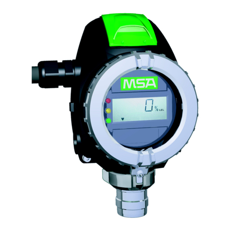
MSA Ultima X User manual

Order No.: 10082867/00
Operating Manual
ULTIMA®X
Gas Monitors with X3TM Technology
Addendum

MSA AUER GmbH
D-12059 Berlin
Thiemannstrasse 1
Germany
© MSA AUER GmbH. All rights reserved

GB
MSA DECLARATION OF CONFORMITY
ULTIMA®X 3 TM 3-1
Declaration of conformity
Manufactured by: Mine Safety Appliances Company
1000 Cranberry Woods Drive
Cranberry Township, PA 16066 USA
The manufacturer or the European Authorized Representative:
MSA AUER GmbH, Thiemannstraße 1, D-12059 Berlin
declares that the product: MSA ULTIMA®XE / X3 TM
based on the EC-Type Examination Certificate:
DMT 02 ATEX E 202 X
complies with the ATEX directive 94/9/EC, Annex III. Quality Assurance Notification
complying with Annex IV of the ATEX Directive 94/9/EC has been issued by INERIS
of France, Notified Body number: 0080 .
The product is in conformance with the EMC directive 89/336/EC, changed by
Directive 91/263/EC, 92/31/EC, 93/68/EC, with the following harmonized norms or
normative documentation:
EN 50 270 Type 2* EN 61 000 - 6 - 3
* EN 61000-4-6: occasional transmission error can appear.
A fault check has to be used at the receiver unit.
We further declare that the product complies with the provisions of LVD
Directive 73/23/EC as amended by Directives 93/68/EC, with the following
harmonized norms or normative documentation:
EN 61 010
MSA AUER GmbH
Dr. Axel Schubert
R & D Instruments Berlin, February 2007

GB
DECLARATION OF CONFORMITY MSA
3-2 ULTIMA®X 3 TM
Marking, Certificates and Approvals according to the
Directive 94/9/EC (ATEX).
Manufacturer: Mine Safety Appliances Company
1000 Cranberry Woods Drive
Cranberry Township, PA 16066 USA
Product: ULTIMA®XE / X3 TM
Type of protection: EN 50 014, EN 50 018
Performance: none
ULTIMA XE/ X3MAIN:
UB = 19V - 30V, Int.Relais + LEDs,
Digital I/O = 0-5V ,3- wire, (GND, Signal+ , Signal -)
Marking: ULTIMA®XE / X3 TM
II 2G EEx d IIC T5
-40°C ≤Ta ≤+60°C
Sensors: ULTIMA XE, ULTIMA XIR: unchanged
Maximum 1x ULTIMA XIR and 2x ULTIMA XE
EC-Type Examination Certificate: DMT 02 ATEX E 202 X
Quality Assurance Notification: 0080
Year of Manufacture: see Label
Serial Nr.: see Label
EMC Conformance according to the Directive 89/336/EC
EN 50 270 Typ 2* EN 61 000 - 6 - 3
* EN 61000-4-6: occasional transmission error can appear.
A fault check has to be used at the receiver unit.

GB
MSA
ULTIMA®X 3 TM 3-3

GB
CONTENTS MSA
4ULTIMA®X 3 TM
Contents
1. Safety Regulations..............................................................................................6
1.1. Correct Use................................................................................................ 6
1.2. Liability information .................................................................................... 6
1.3. Safety and Precautionary Measures to be Adopted ................................... 7
2. Description........................................................................................................... 8
2.1. General View Gas Monitor ......................................................................... 8
2.2. Components............................................................................................... 9
3. Installation .........................................................................................................11
3.1. Instructions for installation........................................................................ 11
3.2. Installation with Mounting Kit.................................................................... 12
3.3. Electrical connection for ULTIMA X3TM instruments ............................... 13
4. Operation ...........................................................................................................15
4.1. Hand-held Controller and Calibrator......................................................... 15
4.2. ModBUS Addressing................................................................................ 16
4.3. ModBUS Communications ....................................................................... 17
4.4. Supported ModBUS Function Codes ....................................................... 17
4.5. ModBUS Memory Map Overview............................................................. 17
4.6. ModBUS Base Address (Read/Write) ...................................................... 17
4.7. ModBUS Factory Configuration Data (Read Only)................................... 18
5. Calibration.......................................................................................................... 19
5.1. Optional RESET button............................................................................ 20
5.2. ModBUS Port ........................................................................................... 21
5.3. ModBUS Communications ....................................................................... 21
6. Maintenance....................................................................................................... 22
7. Technical Data...................................................................................................23
7.1. Dimensions, weight .................................................................................. 23
7.2. Performance Specifications...................................................................... 23
8. Order Information..............................................................................................24

GB
MSA CONTENTS
ULTIMA®X 3 TM 5
Appendix A Electrical installation .......................................................................25
A-1. Installation Drawings ................................................................................ 25
A-2. Cable Lengths and Power Consumption .................................................. 25
A-3. Connection Drawings ............................................................................... 27
Appendix B ModBUS User Configuration Data..................................................28
B-1. ModBUS User Configuration Data............................................................ 28
B-2. Alarm Function Codes - Word 1 ............................................................... 29
B-3. Alarm Function Codes - Word 2 .............................................................. 29
B-4. ModBUS Device Status ........................................................................... 30
B-5. ModBUS General Status Bits .................................................................. 31
B-6. ModBUS Fault Status Bits ....................................................................... 32
B-7. Control Words ......................................................................................... 32
B-8. ModBUS Command Word 1 ................................................................... 33
B-9. ModBUS Command Word 2 ................................................................... 33
B-10. Gas Type.................................................................................................. 34
B-11. Sensor Engineering Units......................................................................... 35
B-12. Information Flags Word 1 ........................................................................ 35
B-13. Information Flags Word 2 ........................................................................ 35
B-14. Information Flags Word 3 ......................................................................... 36
B-15. Information Flags Word 4 ........................................................................ 36
B-16. Alternate Gas Readings .......................................................................... 37
Appendix C Option for internal relay...................................................................38
C-1. Relay connections.................................................................................... 38

GB
SAFETY REGULATIONS MSA
6ULTIMA®X 3 TM
1. Safety Regulations
1.1. Correct Use
This ULTIMA®X3 TM manual is an Addendum to the ULTIMA X Series
Operating Manual (Order No.: 10050078). When installing, commissioning,
calibrating or maintaining the ULTIMA®X3 TM Gas Monitor both manuals
are required.
The ULTIMA®X3 TM Gas Monitors are fixed gas monitors for measuring toxic and
combustible gases as well as oxygen. They are suitable for outdoor and indoor
applications without limitations, e.g. offshore industry, chemical and
petrochemical industry, water and sewage industry. Using sensors, the
instruments test the ambient air and trigger the alarm as soon as the gas exceeds
a specific concentration level.
It is imperative that this operating manual be read and observed when using the
ULTIMA®X3 TM Gas Monitors. In particular, the safety instructions, as well as the
information for the use and operation of the apparatus, must be carefully read and
observed. Furthermore, the national regulations applicable in the user's country
must be taken into account for a safe use.
Alternative use, or use outside this specification will be considered as non-
compliance. This also applies especially to unauthorised alterations to the
apparatus and to commissioning work that has not been carried out by MSA or
authorised persons.
Danger!
This product is supporting life and health. Inappropriate use,
maintenance or servicing may affect the function of the device and
thereby seriously compromise the user’s life.
Before use the product operability must be verified. The product must
not be used if the function test is unsuccessful, it is damaged, a
competent servicing/maintenance has not been made, genuine MSA
spare parts have not been used.
1.2. Liability information
MSA accepts no liability in cases where the product has been used
inappropriately or not as intended. The selection and use of the product are the
exclusive responsibility of the individual operator.
Product liability claims, warranties also as guarantees made by MSA with respect
to the product are voided, if it is not used, serviced or maintained in accordance
with the instructions in this manual.

GB
MSA SAFETY REGULATIONS
ULTIMA®X 3 TM 7
1.3. Safety and Precautionary Measures to be Adopted
Attention!
The following safety instructions must be observed implicitly. Only in
this way can the safety and health of the individual operators, and the
correct functioning of the instrument, be guaranteed.
1. The instruments are used to detect gases or vapours in air. The
concentration of gases or vapours in steam or inerted and oxygen-deficient
atmospheres cannot be measured with this instrument. For oxygen
deficiency measurements, use the oxygen sensor.
2. Protect the ULTIMA®X3 TM Gas Monitor from extreme vibration. Do not
mount the sensing head in direct sunlight as this may cause overheating of
the sensor.
3. Electrochemical sensors are sealed units which contain a corrosive
electrolyte. Should a sensor develop leakage, it must be immediately
removed from service and disposed of properly. Caution must be exercised
so that the electrolyte does not contact skin, clothing or circuitry otherwise
personal injury (burns) and/or equipment damage may result.
4. To ensure the ULTIMA®X3 TM Gas Monitor is operating correctly, it must be
checked with a known concentration of test gas. Therefore, calibration
checks must be carried out regularly as part of the routine inspection of the
instrument.
5. As with all gas monitors of these types, high levels of, or long exposure to,
certain compounds in the tested atmosphere could contaminate the sensor.
In atmospheres were the ULTIMA®X3 TM Gas Monitor may be exposed to
such materials, calibration must be performed frequently to ensure that the
operation is dependable and display indications are accurate.
6. The ULTIMA®X3 TM Gas Monitor must not be painted. If painting is done in
an area where a monitor is located, care must be exercised to ensure that
paint is not deposited on the sintered metal flashback arrestor in the gas
sensor inlet, if so equipped. Such paint deposits would interfere with the gas
diffusion process.

GB
DESCRIPTION MSA
8ULTIMA®X 3 TM
2. Description
The ULTIMA®X3 TM instruments are housed in a flameproof enclosure and are
calibrated at the factory ready for installation.
The instrument components vary somewhat depending on the particular model.
All models are provided with either ¾“ NPT or M25 x 1.5 cable entries.
2.1. General View Gas Monitor
Fig. 1 ULTIMA – Gas Monitor (ULTIMA XE shown here)
1 Housing cover with viewing window
2 Sensor electronics with optional LEDs and display
3 Display
4 Housing ( flameproof enclosure)
5 Sensor housing
6 Sensor module
7 Sensor Guard
6
7
5
4
21 3

GB
MSA DESCRIPTION
ULTIMA®X 3 TM 9
2.2. Components
Display
The display cycles through each connected sensor showing the gas type, gas
concentration and sensor number.
Fig. 2 Sensor Display View
A Gas Type Display 1 Heartbeat - acknowledges commu-
nications activity from ModBUS or IR
Controller/Calibrator command
B Gas Concentration Display 2 Sensor Number
C Gas Concentration Display with Alarm
Indication 3 Alarm Levels
Gas alarm conditions are shown by ALARM and the corresponding number of the
alarm level that is activated.
The display will latch on a gas alarm or fault condition and requires to be reset by
the user to resume cycling.
If multiple conditions exist, acknowledging one condition will reveal subsequent
alarm/fault conditions. Display cycling of sensors will resume when all conditions
have been reset
A B
C
1 2
3

GB
DESCRIPTION MSA
10 ULTIMA®X 3 TM
Relays
The ULTIMA®X3 TM continues to monitor for all gas alarms and faults and will
activate the relays even when the display is latched/locked by a previous alarm
condition. The ULTIMA®X3 TM is shipped with all gas alarm relays configured for
3 alarm levels common to all sensors. Using the ULTIMA/ULTIMA X Controller
(ÆSection 4.1) or ModBUS command each relay can be assigned to one sensor,
providing one level of alarm for each.
The relays have Single Pole Double Throw (SPDT) contacts rated at 30 V DC or
250 V AC (5 A).
The relays may be configured as:
Normally energised/de-energised
Increasing/decreasing level alarm
Latching/non-latching.
Sensor
A sensors gas type, alarm levels and relay configuration are automatically
recognised when connected to a ULTIMA®X3 TM Gas Monitor,. When a sensor is
removed, a "Sensor Missing" scrolling message is displayed; this can be
corrected by:
Reconnecting a sensor to that position or
Manually taking the sensor 'off-line' via:
ULTIMA/ULTIMA X Controller, by sending a sensor disable command or
ModBUS command write to a control register.
A missing or unused sensor position returns a gas value of -99.9 in response to a
ModBUS request for gas level value starting at address base +207.

GB
MSA INSTALLATION
ULTIMA®X 3 TM 11
3. Installation
ULTIMA®X3 TM Gas Monitors should be installed where gas leaks are expected.
The installed location depends on the density of the gas being monitored, higher for
gases lighter than air and lower for gases heavier than air. The display on the front
of the instrument must always be clearly visible and have an unobstructed view.
Before beginning the installation, with the help of the shipping
documents and the sticker on the shipment carton, check that the
delivered components are complete and correct.
3.1. Instructions for installation
ULTIMA®X3 TM Gas Monitors must be installed with the toxic, oxygen or
combustible catalytic sensor inlet points downwards to avoid clogging of the
gas inlet by particles or liquids. Infrared combustible gas sensors must be
installed with the sensor horizontal to prevent accumulation of dirt or
moisture on the optics.
Instruments from the ULTIMA®X3 TM Gas Monitors must not be painted.
When painting, always make sure that no paint falls on the sensor inlet
fitting. Paint deposits can prevent the gas diffusion process where gas from
the atmosphere diffuses into the sensor. In addition, any solvents in the paint
may activate the alarm.
Instruments from the ULTIMA®X3 TM Gas Monitors must be protected from
external vibrations and direct sunlight.
For details of the instrument cabling and electrical connection
(ÆAppendix A-1) and the installation drawings in the ULTIMA X Series
Operating Manual (Order No. 10050078).

GB
INSTALLATION MSA
12 ULTIMA®X 3 TM
3.2. Installation with Mounting Kit
ULTIMA®X3 TM Gas Monitors are installed at the place of installation on a
mounting plate.
Fig. 3 Mounting plate
1 Wall mounting fixing holes
2 Instrument fixing holes
Use Ø6 x 20 mm screws and suitable plugs for attaching the mounting
plate to the wall.
M6 x 20 screws will also be required for fixing the mounting plate to the
ULTIMA®X3 TM Gas Monitor enclosure.
When preparing the assembly, make sure that the mounting
arrangement is correct for the particular instrument type.
Mount the instrument as follows:
(1) Using the mounting plate as a template, mark the holes for the four fixing
screws.
(2) Drill four holes of appropriate diameter.
(3) Attach mounting plate to the Gas Monitor enclosure with M6 x 20 screws.
(4) Attach Gas Monitor with mounting plate, using four Ø6 x 20 screws, at the
place of installation.
During assembly, the ULTIMA®X3 TM Gas Monitor enclosure can be
rotated 360°, to ensure easy access to any of the four cable entries. For
correct positioning of the display, the electronics assembly can be
installed in any of the four self-aligning positions.
2
1
1

GB
MSA INSTALLATION
ULTIMA®X 3 TM 13
3.3. Electrical connection for ULTIMA X3TM instruments
Attention!
The ULTIMA X³ TM instruments must be installed only in compliance
with the applicable regulations, otherwise safe operation of the
instrument is not guaranteed.
Ensure all sources of electrical power are disconnected before
connecting any wires to the ULTIMA®X3TM Gas Monitor.
When using ModBUS communication a network can consist of up to 31 monitors.
Each monitor can support up to three sensors. Total number of sensors is 93.
Power
Maximum power cable length depends on sensor configuration and wire gauge
(ÆAppendix A-2).
Gas Monitor Remote Sensor Distance
Maximum transmitter-to sensor distance is 15 m. For wiring requirements observe
the:
installation drawings (ÆAppendix A-1)
cable lengths and cross-sections (ÆAppendix A-2)
ModBUS communications wiring (ÆAppendix A-3)

GB
INSTALLATION MSA
14 ULTIMA®X 3 TM
Fig. 4 Typical ModBUS Network Topography
A Communications Cable Trunk
B Communications Cable Branch
C Communications and Power Cables remote sensor
1 ModBUS Master Device
2 COM line termination device
3 DC or AC Power Source
4 Device 1
5 Device 2
6 Local DC or AC Power Source
7 Device n
8 COM line termination device
7
4 5
B
C
23 6
8
1
A

GB
MSA OPERATION
ULTIMA®X 3 TM 15
4. Operation
4.1. Hand-held Controller and Calibrator
The intrinsically safe ULTIMA/ULTIMA X Series Controller and Calibrator are
used to calibrate and change or view the configuration of ULTIMA®X3 TM Gas
Monitors.
All firmware versions of the Calibrator will work with the ULTIMA®X3 TM
Gas Monitors but the Controller must have firmware version 3.03 or
later.
A Controller firmware upgrade kit is available (ÆOrdering Information in
the ULTIMA X Series Operating Manual).
ULTIMA/ULTIMA X Calibrator
A simple to use three button device with a non-invasive IR
interface to the ULTIMA®X3 TM Gas Monitor to perform the
following functions:
Zero
Calibration (zero and span )
Address change (for specific models)
(ÆULTIMA/ULTIMA X Series Controller and Calibrator
Operating Manual).
ULTIMA/ULTIMA X Controller
The ULTIMA/ULTIMA X Series Controller with a non-invasive IR
interface provides all the functions of the Calibrator plus access
to the following features:
Three alarm levels and relays
Date of last successful calibration
Change the factory-set test gas value
Change the upper measuring range limit
Display of minimum, maximum and average gas concentration
(ÆULTIMA/ULTIMA X Series Controller and Calibrator
Operating Manual).

GB
OPERATION MSA
16 ULTIMA®X 3 TM
4.2. ModBUS Addressing
Baud rate and data format defaults are adjustable by using a hand-held Controller
or ModBUS command.
Each ULTIMA®X3 TM Gas Monitor is a slave on the communications network and
must have a unique address.
The ModBUS slave address has a valid range of 1-247. The default value is 247.
This address may be set using a ULTIMA/ULTIMA X Controller or Calibrator or a
ModBUS Controller. The Calibrator address range is limited to 0-32, for other
addresses use the Controller.
ULTIMA/ULTIMA X Controller:
“ADDRESS“ – Send an address command with the desired value.
ULTIMA/ULTIMA X Calibrator:
Press “ADDRESS“ button once to display the current setting.
The “ZERO“ increments the address number.
The “SPAN“ button decrements the address number.
Press “ADDRESS“ button again to save the new addresses.
Fore more information ÆULTIMA/ULTIMA X Series Controller and
Calibrator Operating Manual.
ModBUS Controller:
Write address to the corresponding register in the data table.

GB
MSA OPERATION
ULTIMA®X 3 TM 17
4.3. ModBUS Communications
The communications protocol is ModBUS RTU over an RS-485 hardware
network. The default settings for communications parameters are 19200 baud
and even parity. The stop bits are fixed at 1 stop bit. For data types that are larger
than one word, the most significant word is located in the first register (big-
endian).
4.4. Supported ModBUS Function Codes
Function number Description
3 Read Holding Registers
5 Write Single Coil
6 Write Single Register
16 Write Multiple Registers
4.5. ModBUS Memory Map Overview
The ModBUS port allows for access to a significant amount of information which
may be necessary for your system integration requirements. As a minimum, the
gas readings and fault status registers should be polled.
Description Start
Address End
Address Size in
words Access
ModBUS Data Table
Start Base Address 1000 1000 1 Read/Write
Factory Configuration
Data Base +1 Base +18 18 Read Only
User Configuration
Data Base +101 Base +148 48 Read/Write
Status Information Base +201 Base +253 53 Read Only
Control Words Base +301 Base +302 2 Read/Write
4.6. ModBUS Base Address (Read/Write)
The ModBUS base address register is located at address 1000 and has a default
value of 40000. This may be changed by writing a new value within the permis-
sible range to that address. Subsequent addresses must take this new base
address into consideration. The base address may be changed by writing to
address 1000, regardless of its contents.
Description Address Possible Value
ModBUS Data Table Base Address 1000 1000 - 60000
(default 40000)

GB
OPERATION MSA
18 ULTIMA®X 3 TM
For systems that use five-digit addressing, 4XXXX:
If the first digit is an internal system requirement and does not appear in the
communications packet, write the value 1000 to address 41000.
The base address is now 41000 and the first valid address is 41001.
If all five digits appear in the communications packet, the default base address
is 40000 and the first valid address is 40001.
For systems that use six-digit addressing, 4XXXXX:
The first digit is an internal system requirement and does not appear in the
communications packet. The base address is 440000, and the first valid
address is 440001.
4.7. ModBUS Factory Configuration Data (Read Only)
Description Address Possible Value
Device Type Base +1 3 (ULTIMA X3 US);
4 (ULTIMA X3 Europe)
Firmware Version Base +2
00.00 to 99.99
0..32767 integer
divide by 100 for range
Relays Option Installed Base +3 0 - Relays not installed
1 - Relays installed
Reserved for future use Base +4
Sensor 1, Date of Mfg Year, Base +5 20XX
Sensor 1, Date of Mfg Month, Base +6 1 … 12
Sensor 1, Date of Mfg Day, Base +7 1 … 31
Sensor 2, Date of Mfg Year, Base +8 20XX
Sensor 2, Date of Mfg Month, Base +9 1 … 12
Sensor 2, Date of Mfg Day, Base +10 1 … 31
Sensor 3, Date of Mfg Year, Base +11 20XX
Sensor 3, Date of Mfg Month, Base +12 1 ... 12
Sensor 3, Date of Mfg Day, Base +13 1 … 31
Full Scale Range Sensor 1 Base +14 Single Precision Float
Full Scale Range Sensor 2 Base +16 Single Precision Float
Full Scale Range Sensor 3 Base +18 Single Precision Float
Other manuals for Ultima X
1
This manual suits for next models
2
Table of contents
Other MSA Gas Detector manuals
Popular Gas Detector manuals by other brands

JB
JB LDC-4000 operating manual

Bosean Electronic Technology
Bosean Electronic Technology BH-90E Operation manual

BW Technologies
BW Technologies GasAlert MicroClip XT instructions

New Cosmos Electric
New Cosmos Electric XA-4400II instruction manual

Gazomat
Gazomat Inspectra operating manual

Halma
Halma SENSITRON SMART3-R LITE manual