manuals.online logo
Brands
  1. Home
  2. •
  3. Brands
  4. •
  5. AVE
  6. •
  7. Security Sensor
  8. •
  9. AVE AF962 User manual

AVE AF962 User manual

Apparecchiature elettriche ed elettroniche
Electric and electronic equipment
Appareillage électrique et électronique
Equípos electrícos y electronícos
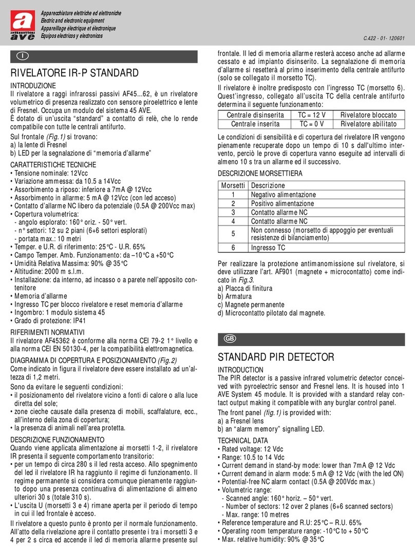
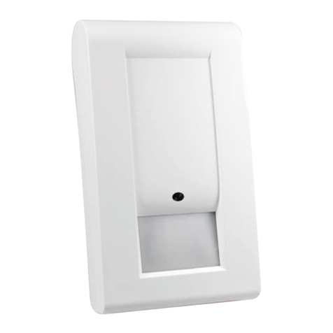
RIVELATORE IR-P STANDARD DA PARETE
INTRODUZIONE
Il rivelatore a raggi infrarossi passivi
AF962, è un rivelatore volumetrico di
presenza realizzato con sensore piroe-
lettrico e lente di Fresnel in contenito-
re tale da permetterne l’installazione a
parete. E’ dotato di un’uscita “stan-
dard” a contatto di relè, che lo rende
compatibile con tutte le centrali anti-
furto.
Fig.1
a) ponticello contaimpulsi
b) ponticello abilitazione accensione led L1(J2)
c) contatto tamper
d) LED (L1)
CARATTERISTICHE TECNICHE
• Tensione nominale: 12Vcc
• Variazione ammessa: da 10.5 a 14Vcc
• Assorbimento a riposo: inferiore a 7mA @ 12Vcc
• Assorbimento in allarme: 5 mA @ 12Vcc (con led acceso)
• Contatto d’allarme NC libero da potenziale (0.5A @ 200Vcc max)
• Protezione contro l’apertura dell’involucro con contatto NC
• Copertura volumetrica:
- angolo esplorato: 140° oriz. - 70° vert.
- n° settori: 22 su 3 piani (13+6 +3 settori esplorati)
- portata max.: 15 metri
• Temper. e U.R. di riferimento: 25°C - U.R. 65%
• Campo Temper. Amb. Funzionamento: da –10°C a +50°C
• Umidità Relativa Massima: 90% @ 35°C
• Altitudine: 2000 m s.l.m.
• Installazione: da interno, a parete o ad angolo, con possibilità di
utilizzo dello snodo cod. AF961
• Contaimpulsi (selezionabile tramite J1): intervento al primo
impulso o al terzo impulso
• Materiale: ABS colore bianco
• Ingombro: (80 x 66 x 46)mm
• Grado di protezione: IP40
RIFERIMENTI NORMATIVI
Il rivelatore AF962 è conforme alla norma CEI 79-2 1° livello e alla
norma CEI EN 50130-4, per la compatibilità elettromagnetica.
DIAGRAMMA DI COPERTURA E POSIZIONAMENTO
(Fig.2)
Come indicato in figura il rivelatore deve essere installato ad un’al-
tezza di 2 metri.
Sono da evitare le seguenti condizioni:
• il posizionamento del rivelatore vicino a fonti di calore o alla luce
diretta del sole;
• zone cieche causate dalla presenza di mobili, scaffalature, ecc.,
all’interno della zona di copertura;
• la presenza di animali nell’area protetta.
DESCRIZIONE FUNZIONAMENTO
Quando viene applicata alimentazione ai morsetti 5-6, il rivelatore IR
presenta il seguente comportamento transitorio (con J2 inserito):
• per un tempo di circa 280 sec. il led L1 resta acceso. Allo spe-
gnimento del led L1 il rivelatore IR ha raggiunto il regime di fun-
zionamento. Il regime permanente si considera comunque piena-
mente raggiunto dopo una presenza continuativa di alimentazio-
ne di almeno ulteriori 30 sec. (totale 310 sec.)
• L'uscita U (morsetti 3 e 4) rimane aperta per il periodo di tempo
in cui il led è acceso.
Il rivelatore a questo punto è pronto per il normale funzionamento.
All’atto della rivelazione apre il contatto presente tra i morsetti 4 e
5 per 2 sec. circa.
Il ponticello J1 permette di selezionare il numero di impulsi di
allarme necessari a far intervenire il rivelatore:
• J1 inserito: intervento immediato, al primo impulso d’allarme
• J1 disinserito: intervento ritardato, al terzo impulso d’allarme
Il ponticello J2 consente di escludere o abilitare l’accensione del
led L1 all’atto della rivelazione:
• J2 inserito: accensione abilitata
• J2 disinserito: accensione esclusa
Le condizioni di sensibilità e di copertura del rivelatore IR vengono
pienamente recuperate dopo un tempo di 10 sec. dall'ultimo inter-
vento, perciò le prove di copertura vanno eseguite ad intervalli di
almeno 10 sec. tra un allarme ed il successivo.
DESCRIZIONE MORSETTIERA
WALL-MOUNTING STANDARD
PIR DETECTOR
INTRODUCTION
The AF962 passive infrared detector is
a presence volumetric detector con-
ceived with pyroelectric sensor and
Fresnel lens. Its special enclosure
allows it to be wall-mounted. It is pro-
vided with a standard relay contact
output making it compatible with any
burglar control panel.
(fig.1)
a) Pulse-counting jumper
b) L1 (J2) led switch on jumper.
c) Tamper contact
d) LED (L1)
TECHNICAL DATA
• Rated voltage: 12 Vdc
• Range: 10.5 to 14 Vdc
I
Morsetti Descrizione
1Contatto protezione antimanomissione (Tamper)
2Contatto protezione antimanomissione (Tamper)
3Contatto allarme NC
4Contatto allarme NC
5Negativo alimentazione
6Positivo alimentazione
G
C.423 - 00 - 110900
C.423 4-06-2002 10:15 Pagina 1
• Current demand in stand-by mode: lower than 7mA @ 12 Vdc
• Current demand in alarm mode: 5 mA @ 12 Vdc (with Led on)
• Potential-free NC alarm contact (0.5A @ 200Vdc max.)
• Protection against any opening of the enclosure through a NC
contact
• Volumetric range:
• Scanned angle: 140° horiz. – 70° vert.
• Number of sectors: 22 over 3 planes (13+6+3 scanned sectors)
• Max. range: 15 metres
• Reference temperature and R.U: 25°C – R.U. 65%
• Operating room temperature range: -10°C to + 50°C
• Max. relative humidity: 90% @ 35°C
• Altitude: 2000 m o.s.l.
• Mounting: indoor, surface or angle-mounting. Possibility of
using the AF961 articulated joint
• Pulse-counter (selectable through Jp-1): tripping at first or third
pulse
• Material: white ABS
• Overall dimensions: (80x66x46) mm
• Protection degree: IP40
STANDARD REFERENCE
The AF960 detector complies to the IEC 79.2 standard 1st level
and to the IEC EN 5013-4 electromagnetic compatibility standard
RANGE AND POSITIONING DIAGRAM
(fig.2)
The detector must be installed at a 2 m height as shown in the
figure:
The following conditions must be observed:
• Do not install the detector near heat sources or in direct sunlight.
• Do not install the detector in areas covered by furniture, shelves,
etc.. inside the coverage area;
• Avoid the presence of animals inside the protected area.
OPERATING DESCRIPTION
On exciting terminals 5-6, the IR detector is affected by the fol-
lowing transient stabilization (with J2 on):
• For 280 s approx. the LED remains ON. As soon as the LED swit-
ches OFF, the IR detector will operate under steady conditions.
However the permanent operating state is reached after another
30s. power supply (totally 310 s.)
• The U output (terminals 3 and 4) remains open during the time
the LED is ON.
The detector is now ready to operate normally. When detecting, it
opens the contact between terminals 4 and 5 for 2 sec. approxi-
mately.
Jumper J1 is used to select the number of alarm pulses required
to make the detector trip:
• J1 ON: immediate tripping at the first alarm pulse
• J1 OFF: delayed tripping at the third alarm pulse.
Jumper J2 allows the L1 led to be switched ON or OFF, upon
detection.
• J2 ON: switch on enabled
• J2 OFF: switch on disabled
Sensitivity and ranging conditions of the IR detector are comple-
tely restored after 10 s from the last tripping, therefore range tests
must be performed at least every 10 s. after one alarm and the
other.
TERMINAL BOARD DESCRIPTION
DÉTECTEUR MURAL STANDARD À
RAYONS INFRAROUGES
INTRODUCTION
Le détecteur à rayons infrarouges
passifs AF962 est un détecteur
volumétrique de présence. La partie
de détection utilise un capteur pyroé-
lectrique et une lentille de Fresnel. Il
est équipé d’une sortie “ standard ” à
contact de relais le rendant compati-
ble avec toutes les centrales antivol.
(fig.1)
a) Barrette compte-impulsions
b) Barrette d’activation allumage DIODE L1 (J2)
c) Contact Tamper.
d) DIODE (L1)
CARACTÉRISTIQUES TECHNIQUES
• Tension d’alimentation: 12 Vcc
• Variation admise: de 10,5 à 14 Vcc
• Absorption au repos : inférieure à 7mA @ 12 Vcc
• Absorption en alarme: 5 mA @ 12 Vdc (avec diode allumé)
• Contact d’alarme NF libre de potentiel (0.5A @ 200Vcc max.)
• Protection contre l’ouverture de l’enveloppe avec contact NF
• Plage volumetrique:
• Angle scannérisé: 140° horiz. – 70° Vert.
• N. de secteurs: 22 sur 3 plans (13+6+3 secteurs scannérisés)
• Portée max.: 15 m.
• Temp. et H.R. de référence: 25°C - H.R. 65%
• Plage de temp. ambiante de fonctionnement: de -10°C à +50°C
• Humidité relative maximale: 90% à 35°C
• Altitude: 2000 m s.n.m
• Mise en place: d’intérieur, murale or en angle. Possibilité d’utili-
ser l’articulation code AF961
• Compte-impulsions (sélectionnable par Jp1) – déclenchement à
la première impulsion ou à la troisième
• Matière: ABS couleour blanche
• Encombrement: (80x66x46) mm
• Degré de protection: IP40
NORMES DE REFERENCE
Le détecteur AF960 est conforme à la norme IEC 79.2 1er niveau
et à la norme CEI EN 50130-4 pour la compatibilité électromagné-
tique.
DIAGRAMME DE COUVERTURE ET POSITIONNEMENT
(Fig. 2)
Le détecteur doit être installé à une hauteur de 2 m.
Terminals Description
1Tampering protection contact (tamper)
2Tampering protection contact (tamper)
3NC alarm contact
4NC alarm contact
5Power supply negative
6Power supply positive
F
C.423 4-06-2002 10:15 Pagina 2
Eviter les conditions suivantes:
• La mise en place du détecteur à proximité de sources de chaleur
ou à la lumière directe du soleil.
• Zones bouchées par la présence de meubles, étagères, etc… à
l’intérieur de la zone de couverture;
• La présence d’animaux dans la zone protégée.
DESCRIPTION DU FONCTIONNEMENT
Lors de la mise sous tension des bornes 5-6, le détecteur IR pré-
sente le comportement transitoire suivant (avec J2 connecté):
• Pendant un temps de 280 s. environ, le diode L1 reste allumé. A
l’extinction du diode L1, le détecteur se stabilise dans la plage
normale de fonctionnement. Cependant la plage de fonctionne-
ment permanente se stabilise après une mise sous alimentation
continue de 30 s. supplémentaires (310 s. au total)
• La sortie U (bornes 3 et 4) reste ouverte pendant un temps au
cours duquel le diode reste allumé.
Maintenant, le détecteur est habilité pour fonctionner normale-
ment. Lorsqu’il y a détection, il ouvre le contact se trouvant entre
les bornes 4 et 5 pendant 2 s. environ.
La barrette J1 permet de sélectionner le nombre d’impulsions d’a-
larme nécessaire au déclenchement du détecteur:
• J1 connecté: déclenchement immédiat, à la première impulsion
d’alarme
• J1 déconnecté: déclenchement retardé, à la troisième impulsion
d’alarme
La barrette J2 permet d’activer ou désactiver l’allumage du diode
L1 lorsqu’il y a détection
J2 connecté: allumage activé
J2 déconnecté: allumage désactivé
Les conditions de sensibilité et d’ouverture du détecteur IR sont
complètement établies après un temps de 10 s. à partir du dernier
déclenchement; les essais de couverture doivent donc être effec-
tuées toutes les 10 s. entre une alarme et la suivante.
DESCRIPTION DE LA BARRETTE DE CONNEXION
DETECTOR ESTÁNDAR DE RAYOS
INFRARROJOS PASIVOS
DE PARED
INTRODUCCIÓN
El detector de rayos infrarrojos pasi-
vos AF962 es un detector volumétrico
de presencia cuya parte dedicada a la
detección utiliza un sensor piroeléctri-
co y una lente de Fresnel. Gracias a su
caja puede ser instalado a la pared.
Bornes Description
1Contact de protection anti-effraction (tamper)
2Contact de protection anti-effraction (tamper)
3Contact d’alarme NF
4Contact d’alarme NF
5Négatif alimentation
6Positif alimentation
Está provisto de una única salida “estándar" de contacto de relé
que lo hace compatible con todas las centrales antirrobo.
(fig. 1)
a) Conector puente cuentaimpulsos
b) Conector puente para el encendido del LED1 (J2)
a) Contacto tamper
b) LED (L1)
CARACTERÍSTICAS TÉCNICAS
• Tensión nominal: 12 Vcc
• Variación admitida: de 10,5 a 14 Vcc
• Consumo en reposo: inferior a 7mA @ 12 Vcc
• Consumo en alarma: 5mA @ 12 Vcc (con el LED encendido)
• Contacto de alarma NC libre de potencial (0,5A @ 200Vcc máx)
• Protección contra la abertura de la envoltura con contacto NC
• Cobertura volumétrica:
• Angulo explorado: 140° horix. – 70° vert.
• N° sectores: 22 sobre 3 planos (13+6+3 sectores explorados)
• Alcance máx: 15 metros
• Temp. y H.R. de referencia: 25°C - H.R. 65%
• Campo de temp. ambiente de funcionamiento: de -10°C a +50°C
• Humedad relativa máxima: 90% a 35°C
• Altitud: 2000 m s.n.m
• Instalación: de interior, de superficie o de angulo; posibilidad de
utilizar la articulación código AF961
• Cuentaimpulsos (seleccionable mediante Jp1) – intervención al
primer impulso o al tercero.
• Material: ABS color blanco
• Medidas: (80x66x46) mm
• Grado de protección: IP40
NORMAS DE REFERENCIA
El detector AF960 es conforme con la norma IEC 79.2 1er nivel y
con la norma CEI EN 50130-4 para la compatibilidad electroma-
gnética
DIAGRAMA DE COBERTURA Y COLOCACIÓN
(Fig. 2)
Come se indica en la figura, el detector tiene que ser instalado a
una altura de 2 m.
Las condiciones siguientes tienen que ser evitadas:
• La colocación del detector a proximidad de fuentes de calor o a
la luz directa del sol.
• Zonas cerradas por muebles, estantes, etc…, al interior de la
zona de cobertura.
• La presencia de animales en la zona protegida.
DESCRIPCIÓN DEL FUNCIONAMIENTO
Cuando se enciende la alimentación a los bornes 5-6, el detector
RI presenta el comportamiento transitorio siguiente (con J2
conectado):
• Durante un tiempo de 280s. aproximadamente el LED L1 perma-
nece encendido. Al apagarse el LED L1, el detector se estabiliza
dentro del campo normal de funcionamiento. Sin embargo, el
campo de funcionamiento se considera permanente después de
una alimentación continua de otros 30 s. por lo menos. (310 s.
en total)
• La salida U (bornes 3 y 4) permanece abierta todo el tiempo
durante el cual el LED está encendido.
Ahora el detector está listo para el funcionamiento normal.
Cuando se produce la detección, el dispositivo abre el contacto
E
C.423 4-06-2002 10:15 Pagina 3
150°
Bornes Descripción
1Contacto de protección contra la abertura sin
autorización (tamper)
2Contacto de protección contra la abertura sin
autorización (tamper)
3Contacto de alarma NC
4Contacto de alarma NC
5Negativo alimentación
6Positivo alimentación
12 3456
J2 P1
L1
J1
Fig. 1 Fig. 2
d
ca b
2 m
15 m
10 m5 m1 m
AVVERTENZE: I prodotti devono essere commercializzati in confezione originale. In caso contrario al riven-
ditore e/o installatore è fatto obbligo di applicare e di trasmettere all'utilizzatore le istruzioni d'uso che
accompagnano il prodotto e che sono riportate anche sui cataloghi, bollettini tecnici, depliants, inserti
ecc.... Dopo aver aperto l'imballaggio assicurarsi dell'integrità dell' apparecchio. In caso di dubbio non uti-
lizzare l'apparecchio e rivolgersi a personale professionalmente qualificato. Si precisa che per l' installazio-
ne dello stesso si rende necessario l'impiego di personale tecnico specializzato. L'apparecchio, anche se
imballato, va maneggiato con cura. La merce va immagazzinata in luogo asciutto a temperatura non supe-
riore a +40°C e non inferiore a -5°C.
Si ricorda inoltre: • Togliere tensione agendo sull'interruttore generale prima di operare sull'impianto. •
Curare in modo particolare la preparazione dei terminali dei cavi da inserire nei morsetti dell'apparecchio,
per evitare la riduzione delle distanze di isolamento tra gli stessi. • Serrare le viti dei morsetti con particola-
re cura per evitare surriscaldamenti che potrebbero provocare un incendio o il danneggiamento dei cavi. •
Il prodotto, se non diversamente specificato, è destinato all'utilizzo in luoghi asciutti e non polverosi. Per
ambienti particolari utilizzare prodotti specifici. • Installare gli interruttori in un quadro, contenitore o
accessorio che assicurino il grado di protezione IP adeguato all'ambiente e all'uso, secondo le prescrizioni
delle norme CEI vigenti per gli impianti elettrici. • La sicurezza la funzionalità e i Marchi di Qualità sono
garantiti solo utilizzando placche, telai e contenitori originali.
NOTE: Products should be sold in their original packaging. When this is not the case, the retailer and/or
installer is obliged to follow, as well as communicate to the user, the instructions of use which are sup-
plied with the product and are also carried in the catalogue, technical bulletins, leaflets, articles, enclosu-
res etc. After opening the packaging check that the appliance is undamaged. Do not use the appliance if
there is any doubt, but contact a qualified technician. The appliance must also be fitted by a qualified tech-
nician. Even before unpacking, the appliance should be handled with care. The goods should be stored in a
dry place at temperatures of not less than –5 °C and not more than +40 °C.
Also note: • Before carrying out any work on the appliance the main power supply switch shall be turned
off, so cutting off the power. • Particular care should be taken in the preparation of the cable terminals to
be inserted into the appliance terminals so as to maintain sufficient isolation distance between them. •
When tightening the terminal screws particular care should be taken to avoid overheating which could
start a fire or damage the cables. • Unless specified otherwise, this product is for use in dry, dust-free
areas. Suitable products should be used in any other conditions. • The switches should be installed onto a
board, container or fitting that ensures the appropriate IP degree of protection for the surrounding condi-
tions and their use, according to the CEI rules and regulations in force for electrical appliances. • The
safety, efficiency and Quality Marks of the product are only guaranteed when it is used with our plates, fra-
mes and containers.
AVERTISSEMENT: Les produits doivent être commercialisés dans leur emballage original. Dans le cas con-
traire, il faut que le détaillant et/ou l'installateur applique et transmette à l'utilisateur les instructions pour
l'emploi qui accompagnent le produit et qui sont indiquées également sur les catalogues, bulletins techni-
ques, dépliants, encarts publicitaires etc... Après avoir ouvert l'emballage, s'assurer que l'appareil est
intact. Dans le doute, ne pas utiliser l'appareil et s'adresser au personnel professionnellement qualifié.
Nous précisons que pour l'installation de ce dernier, l'emploi de techniciens spécialisés est nécessaire.
L'appareil, même s'il est emballé, doit être manipulé avec soin. La marchandise doit être emmagasinée
dans un endroit sec à une température qui ne dépasse pas +40 °C et ne soit pas inférieure à -5 °C.
De plus, rappelez-vous: • D'ôter la tension opérant sur l'interrupteur général avant d'avoir une action sur
l'installation. • D'effectuer soigneusement la préparation des bornes des câbles que l'on doit connecter
aux bornes de l'appareil, afin d'éviter que la distance d'isolement entre elles ne se réduise. • De serrer les
vis des bornes méticuleusement afin éviter des surchauffements qui pourraient provoquer un incendie ou
l'endommagement des câbles. • Le produit, sauf spécifications différentes, est destiné à être employé
dans des lieux secs et exempts de poussières. Pour des milieux ambiants particuliers, utiliser des produits
spécifiques. • Installer les interrupteurs dans un tableau, boîtier ou dispositif qui garantit le degré de pro-
tection IP adéquat au milieu ambiant et à l'emploi, selon les prescriptions des normes CEI en vigueur pour
les installations électriques. • La sécurité, la bonne marche de l'appareil, et les Marques de Qualité sont
garanties seulement si l'on utilise notres plaques, cadres et boîtiers.
ADVERTENCIAS: Los productos se deben comercializar con su embalaje original, de lo contrario el reven-
dedor y/o instalador deberá aplicar y transmitir al utilizador las instrucciones de uso que acompañan el
producto y que se citan también en los catálogos, prospectos técnicos, folletos, etc... Después de abrir el
embalaje compruebe la integridad del aparato. En caso de duda no utilice el aparato y consulte a personal
profesionalmente calificado. Para la instalación del mismo se necesita personal técnico especializado. El
aparato, aunque esta embalado, debe ser manejado con cuidado. La mercancía se debe almacenar en un
lugar seco con una temperatura no superior a +40 °C y no inferior a –5 °C.
Se recuerda asimismo: • Quitar tensión con el interruptor general antes de trabajar en la instalación. •
Preparar atentamente los terminales de los cables a conectar en el bloque terminal del aparato, para evitar
la reducción de las distancias de aislamiento entre los mismos. • Ajustar los tornillos de los bornes aten-
tamente para evitar recalentamientos que podrían provocar un incendio o dañar los cables. • El producto,
cuando no se especifique diversamente, está destinado a usarse en lugares secos y no polvorosos. Para
ambientes particulares usar productos específicos. • Instalar los interruptores en un tablero, recipiente o
accesorio que garantice el grado de protección IP adecuado al ambiente y al uso, conforme a las normas
CEI vigentes para las instalaciones eléctricas. • La seguridad, la funcionalidad y las Marcas de Calidad se
garantizan sólo utilizando placas, bastidores y recipientes de nuestra construcción.
presente entre los bornes 4 y 5 para 2 sec. aproximadamente.
El conector puente J1 permite seleccionar el número de impulsos
de alarma necesarios a la intervención del detector:
• J1 conectado: intervención inmediata, al primer impulso de alar-
ma
• J1 desconectado: intervención retardada, al tercer impulso de
alarma
El conector puente J2 permite habilitar o deshabilitar el encendido
del LED L1 cuando se produce la detección:
• J2 conectado: encendido habilitado
• J2 desconectado: encendido deshabilitado
Las condiciones de sensibilidad y de cobertura del detector RI se
recuperan después de un tiempo de 10s. desde la última interven-
ción, por eso las pruebas de cobertura tienen que ser efectuadas
cada 10 s. entre una alarma y la sucesiva.
DESCRIPCIÓN DEL TABLERO DE BORNES
C.423 4-06-2002 10:15 Pagina 4
Other AVE Security Sensor manuals

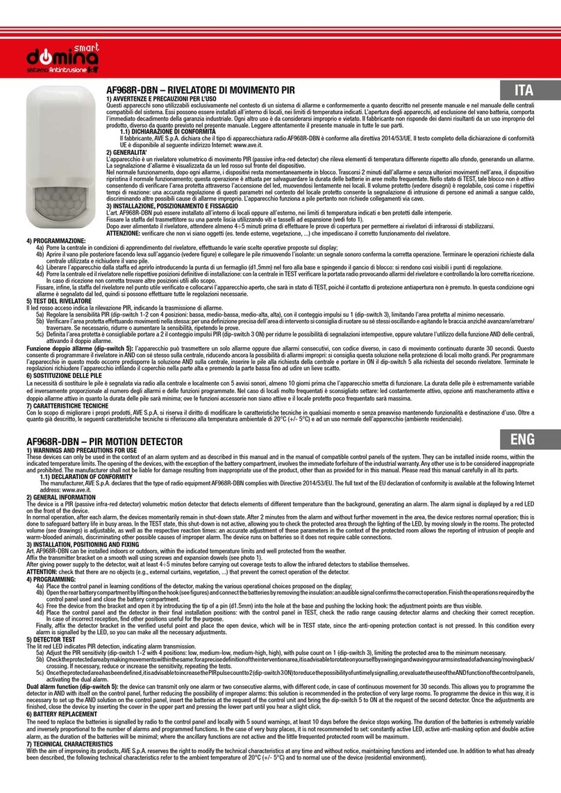
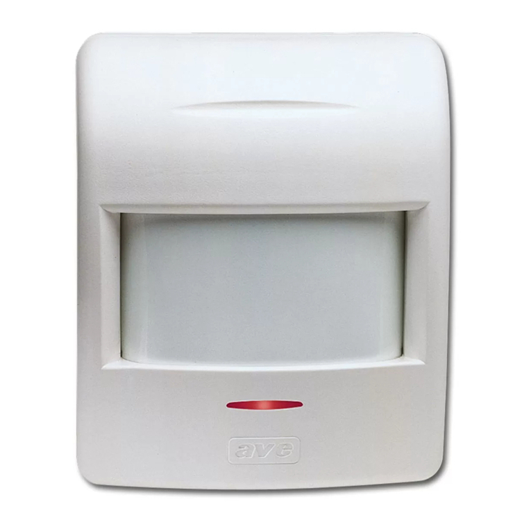
AVE domina AF968R-DBN User manual

AVE

AVE domina AF968R-DBN User manual

AVE LUCE AMICA User manual

AVE

AVE LUCE AMICA User manual

AVE AF974R-DB User manual

AVE

AVE AF974R-DB User manual

AVE AF975R-DB User manual

AVE

AVE AF975R-DB User manual

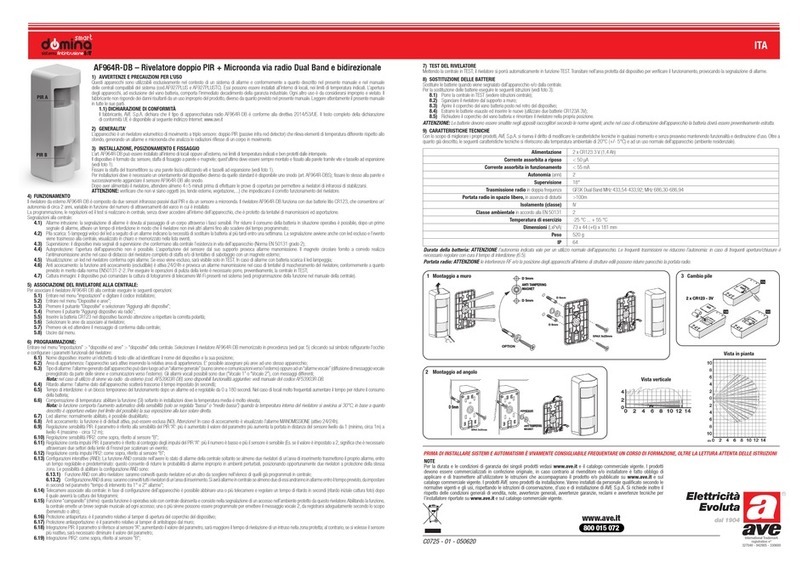
AVE Domina Smart AF964R-DB User manual

AVE

AVE Domina Smart AF964R-DB User manual

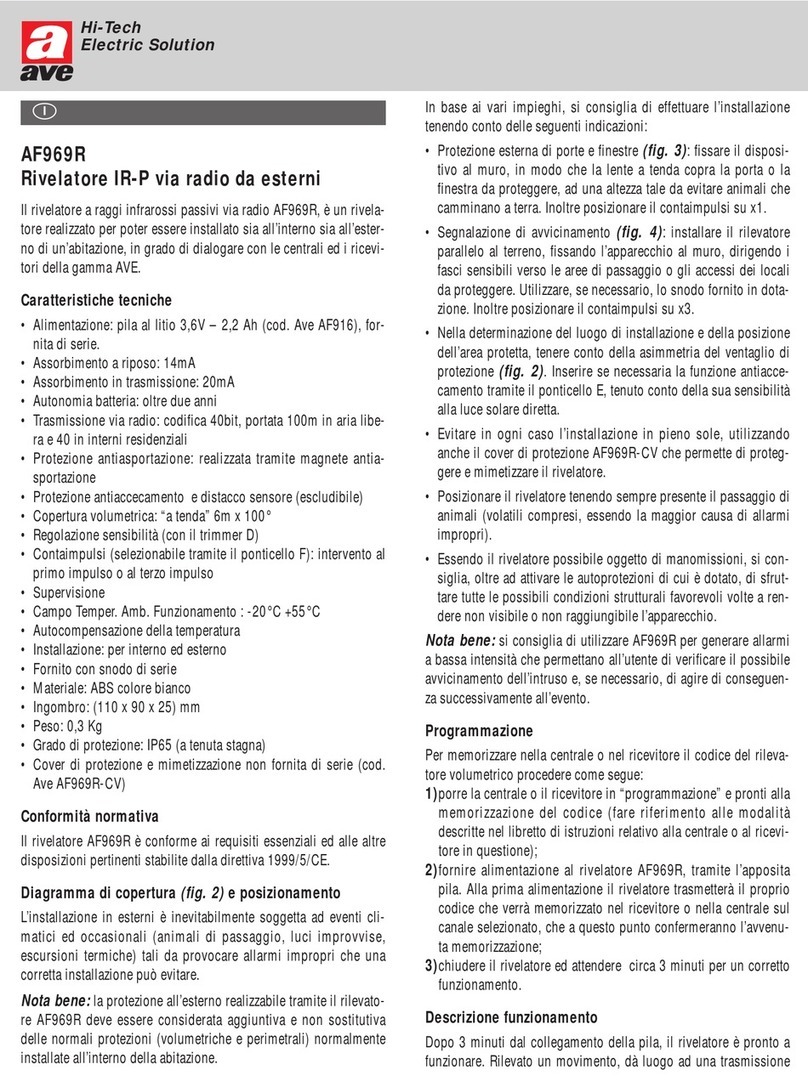
AVE AF969R User manual

AVE

AVE AF969R User manual

AVE AF974R-DB User manual

AVE

AVE AF974R-DB User manual

AVE AF962 User manual

AVE

AVE AF962 User manual

AVE AF970R User manual

AVE

AVE AF970R User manual

AVE AF969R User manual

AVE

AVE AF969R User manual

AVE LUCE AMICA 44 068/3F Series User manual

AVE

AVE LUCE AMICA 44 068/3F Series User manual

AVE AF45362 User manual

AVE

AVE AF45362 User manual

AVE LUCE AMICA 44 068/3F Series User manual

AVE

AVE LUCE AMICA 44 068/3F Series User manual

AVE domina AF976R-DB User manual

AVE

AVE domina AF976R-DB User manual

AVE AF964R-DB User manual

AVE

AVE AF964R-DB User manual

AVE AF45 62 Series User manual

AVE

AVE AF45 62 Series User manual

AVE AF969F User manual

AVE

AVE AF969F User manual

Popular Security Sensor manuals by other brands

MITECH MIKRA Installation and user manual

MITECH

MITECH MIKRA Installation and user manual

jablotron JA-111ST manual

jablotron

jablotron JA-111ST manual

Bircher Reglomat Jupiter operating instructions

Bircher Reglomat

Bircher Reglomat Jupiter operating instructions

ESYLUX EP10427404 operating instructions

ESYLUX

ESYLUX EP10427404 operating instructions

EL EL4855 installation instructions

EL

EL EL4855 installation instructions

Carrier Graviner Mk7 INSPECTION & CLEANING INSTRUCTIONS

Carrier

Carrier Graviner Mk7 INSPECTION & CLEANING INSTRUCTIONS

Applied Strobe AST-14 installation instructions

Applied Strobe

Applied Strobe AST-14 installation instructions

Chamberlain LM21AFCB owner's manual

Chamberlain

Chamberlain LM21AFCB owner's manual

CARLO GAVAZZI SMS user manual

CARLO GAVAZZI

CARLO GAVAZZI SMS user manual

Leeo Smart Alert quick start guide

Leeo

Leeo Smart Alert quick start guide

LEGRAND 0 942 80 manual

LEGRAND

LEGRAND 0 942 80 manual

Berker 85801100 Operation instructions

Berker

Berker 85801100 Operation instructions

LINKIND LL20004 user manual

LINKIND

LINKIND LL20004 user manual

schmersal BNS 300-01ZG operating instructions

schmersal

schmersal BNS 300-01ZG operating instructions

DURRIDGE RAD7 user manual

DURRIDGE

DURRIDGE RAD7 user manual

Hitachi UST-568 instruction manual

Hitachi

Hitachi UST-568 instruction manual

Argus Security TAURUS TW-DT-01 user manual

Argus Security

Argus Security TAURUS TW-DT-01 user manual

Menlo Systems FPD510 operating manual

Menlo Systems

Menlo Systems FPD510 operating manual

manuals.online logo
manuals.online logoBrands
  • About & Mission
  • Contact us
  • Privacy Policy
  • Terms and Conditions

Copyright 2025 Manuals.Online. All Rights Reserved.