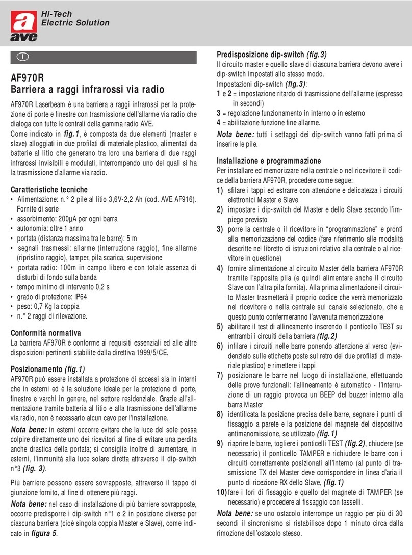
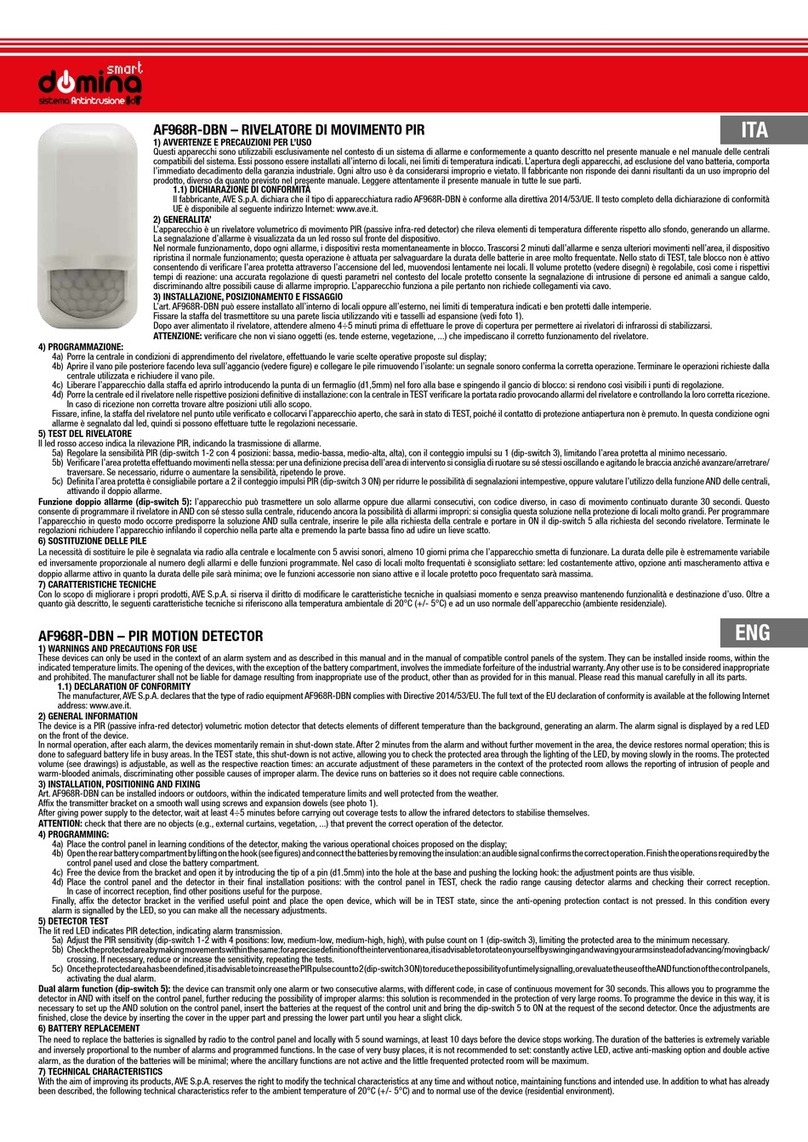
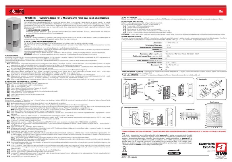
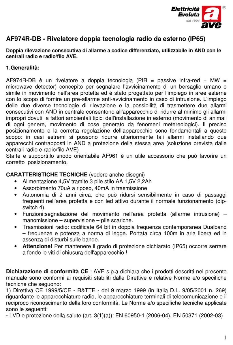
AVE AF974R-DB User manual

International Trademark
registration n°
327040 - 942905 - 330600
Doppia rilevazione consecutiva di allarme a codice differenziato,
utilizzabile in AND con le centrali radio e radio/filo AVE.
Caratteristiche tecniche
1.Generalità:
AF974R-DB è un rivelatore a doppia tecnologia (PIR = passive infra-red + MW
= microwave detector) concepito per segnalare l’avvicinamento di un bersaglio
umano o simile in movimento nell’area protetta ed è stato progettato per l’impie-
go in aree esterne con lo scopo di fornire un pre-allarme anti-avvicinamento in
caso di intrusione. L’impiego delle due diverse tecnologie di rilevazione e la pos-
sibilità di trasmettere due allarmi consecutivi con AND in centrale, consentono
all’apparecchio di ridurre al minimo gli allarmi impropri dovuti a fattori ambientali
tipici dell’installazione in esterno (movimento di animali di ogni genere, movi-
mento di cose generato da fenomeni metereologici). Il preciso posizionamento
e la corretta regolazione dell’apparecchio sono fondamentali a questo scopo:
in casi estremi si possono ridurre ulteriormente tali allarmi installando due ap-
parecchi contrapposti in AND a protezione della stessa area (soluzione prevista
dalle centrali radio e radio/filo AVE).
Staffe e supporti:lo snodo orientabile AF961 è un utile accessorio che può favo-
rire un corretto posizionamento.
CARATTERISTICHE TECNICHE
(vedere anche disegni)
• Alimentazione:4,5V tramite 3 pile stilo AA 1,5V 2,2Ah
• Assorbimento 70uA a riposo, 40mA in trasmissione
• Autonomia di 2 anni circa, che può ridursi sensibilmente in caso di passaggi
frequenti nell’area protetta e con led attivo durante il normale funzionamento
(dip-switch 4).
• Funzioni:segnalazione del movimento nell’area protetta (allarme intrusione)
- manomissione - supervisione - pile scariche.
• Trasmissioni radio: codificate 64 bit in doppia frequenza contemporanea
Dualband – frequenze e potenza a norma di legge. Portata circa 100m in
aria libera ed in assenza di disturbi sulle bande.
•
Attenzione!
Serrare a fondo le viti di chiusura dell’apparecchio!
Dichiarazione di conformità CE
: AVE s.p.a dichiara che i prodotti descritti
nel presente manuale sono conformi ai requisiti stabiliti dalle Direttive e relative
Norme e/o specifiche tecniche che seguono:
1) Direttiva CE 1999/5/CE - R&TTE - del 9 marzo 1999 (in Italia D.L. 9/05/2001
n. 269) riguardante le apparecchiature radio, le apparecchiature terminali di
telecomunicazione e il reciproco riconoscimento della loro conformità. Le Nor-
me e/o specifiche tecniche applicate sono le seguenti:
- LVD e protezione della salute (art. 3(1)(a)): EN 60950-1 (2006-04), EN 50371
(2002-03)
- EMC (art. 3(1)(b)): EN 301 489-1 V1.8.1 (2008-04), EN 301 489-3 V1.4.1
(2002-08), EN 301 489-7 V1.3.1 (2005-11)
- Spettro radio (art. 3(2)): EN 300 220-1 V2.1.1 (2006-04), EN 300 220-2
V2.1.2 (2007-06) In accordo alla direttiva citata, allegato IV, il prodotto risulta
di classe 4 pertanto può essere commercializzato e messo in servizio senza
limitazioni.
2) Direttiva CE 2004/108 del 15 dicembre 2004, per il riavvicinamento delle
legislazioni degli Stati membri relative alla compatibilità elettromagnetica. Le
Norme e/o specifiche tecniche applicate sono le seguenti: EN 50130-4 (1995-
12) + A1 (1998-04) + A2 (2003-01) - EN 55024 (1998-09) +A1 (2001-10)
+ A2 (2003-01) - EN 301489-1 V1.8.1(2008-04) - EN 301489-3 V. 1.4.1
(2002-08) - EN 301489-7 V1.3.1 (2005-11).
3) Direttiva CE 2006/95 del 12 dicembre 2006, per il riavvicinamento delle
legislazioni degli Stati membri relative al materiale elettrico destinato ad essere
adoperato entro taluni limiti di tensione. E’ applicata la Norma EN 60950-1
(2006-049).
Prodotto conforme alla norma EN 50131-1 - Classe ambientale 3 - Prodotto di
categoria I secondo la Norma 300.220 - 1 (04/2006).
2.FUNZIONAMENTO
a) Generalità
:l’apparecchio funziona con 3 pile alcaline tipo AA e trasmette
l’allarme via radio, quindi non richiede fili di collegamento. La parte PIR dell’ap-
parecchio è sempre in funzione ed attiva la parte MW in caso di rilevazione
di intrusione: la conferma Doppler dell’esistenza di una massa in movimento
nell’area genera lo stato di allarme. La sequenza di rilevazione è visualizzata
dal led sul fronte dell’apparecchio, che cambia colore (verde-arancio-rosso) nei
vari passaggi. Programmando due trasmissioni di allarme successive con codice
differente si può utilizzare la funzione AND della centrale.
AF974R-DB
Rivelatore doppia tecnologia
radio da esterno riparato
Blocco per la riduzione del consumo: dopo ogni allarme (o dopo due) l’apparec-
chio resta in momentaneo blocco, che si ripristina trascorsi 2 minuti di assenza
totale di movimenti nell’area. Questo per ridurre il consumo delle pile in aree
molto frequentate.
b) Doppia segnalazione di allarme
: utilizzando l’apparecchio con centrali
radio e radio/filo AVE si può sfruttare la funzione AND. Attraverso il dip-switch 5
si ottiene che il rivelatore trasmette il primo allarme con un codice ed un even-
tuale secondo allarme, che avvenga entro 45 secondi, con un codice diverso.
Programmando quindi il rivelatore sulla centrale come fossero due in AND, si
ottiene che l’allarme vero e proprio scatterà solo in caso di doppia trasmissione
del rivelatore (vedi punto 3a per la programmazione).
c) Regolazioni
: la parte PIR può essere regolata in “sensibilità” (RANGE) e in
conteggio di impulsi (PULSE COUNT), che costituisce in sostanza un ritardo di
intervento. Quella MW si regola in “sensibilità (RANGE) ed integrazione (DELAY),
che è il tempo minimo di durata del movimento rilevato al fine dell’allarme.
d) Protezione antiasportazione
: un apposito magnete, da fissare al muro nel
punto previsto sulla staffa scorrevole, consente la protezione antiasportazione.
Quando il rivelatore è correttamente collocato sulla staffa tale magnete chiude
uno dei tre contatti posti all’interno dell’apparecchio: lo slittamento verso l’alto
o il basso e/o il distacco dell’apparecchio dal muro provoca un allarme “mano-
missione” ed il successivo stato di “test”. Nel caso di installazione del rivelatore
con staffe o snodo accessorio occorre comunque che il agnete sia correttamente
posizionato (vedere disegni) onde consentire il TEST, oltreché realizzare la pro-
tezione.
e) Protezione antiapertura
: aprendo l’apparecchio alimentato un apposito
pulsante comanda la trasmissione di manomissione indipendentemente dalla
condizione del magnete antiasportazione.
f) Condizioni di prova dell’apparecchio (TEST)
: AF974R-DB si pone in
TEST quando viene rimosso dalla sua slitta, dietro la quale è collocato il magnete
solidale con la superficie di fissaggio: ciò provoca allarme manomissione, quindi
sarà necessario porre preventivamente in test la centrale. Lo stato di test dura
per 3 minuti successivi alla ricollocazione corretta dell’apparecchio e visualizza
tramite il led tutte le rilevazioni, annullando il blocco dopo un primo allarme.
Attenzione
Ove non sia possibile installare il magnete antiasportazione occorre
comunque avvicinarlo manualmente ad una delle 3 posizioni possibili e tenerlo in
posizione per almeno 6 secondi ad apparecchio alimentato, onde attivare il con-
trollo (Beep di conferma): allontanandolo si è in TEST (3 min.). successivamente
si attiva il TEST collocando temporaneamente il magnete nella stessa posizione
precedentemente utilizzata per 1 secondo.
Attenzione! L’apparecchio rimane permanentemente in TEST quando il pulsante
TAMPER è aperto (box aperto).
g) Supervisione
: AF974R-DB trasmette un segnale di esistenza in vita ogni
40 minuti circa, che viene gestito dalle centrali supervisionate AVE - vedere
“funzione supervisione” delle centrali utilizzate.
h) Segnalazione di pile scariche
: l’apparecchio segnala via radio alla cen-
trale e localmente con 5 Beep la necessità di sostituzione delle pile.
3.INSTALLAZIONE
- rispettare la sequenza delle operazioni
a) Programmazione dell’apparecchio sulla centrale
o ricevitore (vedere
anche istruzioni della centrale/ricevitore utilizzati):
• Aprire l’apparecchio svitandone le viti sul fondo e aprire il coperchio del vano pile
• Porre la centrale in PROGRAMMAZIONE, in condizione di apprendimento del
rivelatore sulla zona desiderata
• Estrarre la pellicola di isolamento delle pile, alimentando l’apparecchio: un
Beep della centrale conferma la programmazione.
• Terminare la procedura assegnando il nome al rivelatore (etichetta scritta e
vocale sulle centrali). Richiudere il vano pile.
Programmazione doppio allarme: (vedere punto 2 b): in questo caso la centrale
deve essere predisposta per rivelatori in AND, ove la prima programmazione
avviene alimentando l’apparecchio e la seconda ponendo in ON il dip-switch 5.
La centrale confermerà l’operazione.
b) Posizionamento
:
Determinare la posizione e l’altezza di installazione dell’apparecchio in funzione
dell’area protetta che si vuole ottenere, tenendo conto della forma della zona
protetta (vedere figure). L’apparecchio, se installato in senso verticale, forma
una protezione a ventaglio parallela al terreno: valutando attentamente l’altezza
di posizionamento si consente il passaggio di piccoli animali. Se l’apparecchio
è installato in senso orizzontale esso forma una “tenda” verticale o diagonale in
conseguenza della posizione: scegliere la copertura più adatta alle necessità.
Utilizzare lo snodo per il fissaggio ad angolo, avvitandolo sulla staffa scorrevo-
le fornita con l’apparecchio, in modo tale da consentirne l’estrazione. In caso
di dubbi sulla posizione definitiva si consiglia di fissare l’apparecchio in modo
provvisorio ed effettuare le regolazioni e relative prove di rilevazione prima del
fissaggio definitivo. Non posizionare l’apparecchio in pieno sole per evitare il
surriscaldamento interno (effetto serra) : questo non danneggia l’apparecchio,
ma provoca un aumento della sensibilità PIR non necessario qualora sia attivata
la compensazione di temperatura. Evitare il più possibile che l’area protetta sia

aperta alle intemperie (neve, pioggia battente), possibili cause di allarme impro-
prio.
c) Regolazioni (vedere disegno)
:
Per verificare le regolazioni si utilizza il led dell’apparecchio, che va posto in stato
di TEST (vedere paragrafo 2f): Il led verde indica la rilevazione PIR: successiva-
mente cambia colore in arancio quando il movimento è confermato dalla parte
MW; trascorso il tempo di integrazione (PT2 – vedi nota) il led diventa rosso
indicando la trasmissione di allarme. Le prove di rilevazione vanno effettuate
con apparecchio chiuso. Regolare la sensibilità PIR (dip-switch 2), con conteggio
impulsi su 1 (dip-switch 3 in OFF), limitando l’area protetta a quanto effettiva-
mente necessario.
• Regolare la sensibilità della parte MW (RANGE - PT1), con tempo di intervento
al minimo, in conseguenza della regolazione precedente.
• Richiudere l’apparecchio, posizionarlo e verificare l’area protetta attraverso
il led, effettuando movimenti nella stessa: per una definizione precisa dell’area
di intervento si consiglia di ruotare su sé stessi agitando le braccia anziché
avanzare/arretrare/traversare.Se necessario, aprire l’apparecchio e ridurre o
aumentare la portata, ripetendo le prove precedenti.
• Definita l’area protetta, se questa è orizzontale (parallela al terreno) è
consigliabile portare a 2 il conteggio impulsi PIR (dip-switch 3 ON) per ridurre
le possibilità di segnalazioni intempestive. Se si adotta la protezione a tenda
(area protetta verticale) valutare questo aspetto in funzione delle possibilità
di attraversamento veloce.
• Aumentare quindi il tempo di integrazione (DELAY: durata del movimento
nell’area) della parte MW al massimo, compatibilmente con le esigenze di
rilevazione: questo riduce le possibilità di allarmi intempestivi causati preva-
lentemente da animali volanti nell’area protetta.
Esempi di possibili settaggi
:
• per una rilevazione “rapida” a 6m, lasciare tutti i dip switch in OFF tranne
il 6 in ON e regolare entrambi i trimmer (PT1 e PT2), delay e portata, al
valore minimo ruotandoli in senso antiorario.
• per una rilevazione “rapida” a 12m portare i dip switch 2 e 6 in ON, lasciare
gli altri in OFF. Regolare il trimmer della portata della microonda (PT1) al
valore massimo ruotandolo in senso orario mentre il trimmer delay (PT2) al
valore minimo ruotandolo in senso antiorario.
Nota
: il
tempo di integrazione
della microonda (delay regolabile con il trim-
mer PT2), è il tempo di quanto dura il movimento nell’area protetta. Se per
esempio si decide di settare questo tempo a 1,5 sec con il trimmer delay, ciò
significa che, una volta che la sezione infrarosso ha rilevato un intruso e ha
acceso la microonda, se il movimento nell’area protetta perdura per 1,5 sec
o superiore, la microonda fa generare l’allarme, diversamente va a riposo. Un
opportuno settaggio del tempo di integrazione riduce la possibilità di allarmi
impropri.
d) Esclusione led
: sia per motivi di sicurezza che per evitare sovraconsumi
dell’apparecchio occorre escludere l’accensione del led al termine delle prove,
portando in ON il dip-switch 4. In stato di test essi funzioneranno comunque.
Eventuali controlli del funzionamento del rilevatore possono essere eseguiti at-
traverso le funzioni TEST della centrale e/o le spie dei ricevitori.
e) Compensazione di temperatura
: la funzione consiste nell’aumento au-
tomatico della sensibilità PIR quando la temperatura nell’apparecchio supera i
30°C e si attiva ponendo in ON il dip-switch 6. Come descritto al punto b) di
questo paragrafo occorre considerare che in caso di esposizione al sole la tem-
peratura all’interno dell’apparecchio può essere decisamente superiore a quella
ambientale, che non richiede quindi aumenti di sensibilità.
AF974R-DB
Dual technology radio
detector for sheltered
outdoor use
Two consecutive alarm detections with different code for AND use
with wireless and wireless/wired AVE central units
1. Main features:
AF974R-DB is a detector with double technology (PIR = passive infra-red detec-
tor + MW = microwave Doppler detector) developed to indicate the approach of
a human target or similar in movement in the protected area and it has been de-
signed for use in outdoor areas with the purpose of supplying an anti-approach
pre-alarm in the case of intrusion. The use of Dual Tech technology and the
“double alarm” function allows the detector to reduce the possibility of improper
alarms, due to typical environmental factors linked to outdoor installation (move-
ment of animals of all types, movement of objects a/o meteorological phenome-
non). Precise positioning and correct regulation of the detector are fundamental
for this scope: in extreme cases it is possible to reduce these alarms even further
by installing two opposite detectors in AND to protect the same area (solution
envisioned by the AVE control panels). Brackets and supports :the movable joint
AF961 is an useful accessory that can favour correct positioning.
TECHNICAL FEATURES
(see diagrams also)
• Power supply:4.5V via 3 AA 1.5V 2.2Ah batteries
• Absorption 70uA at rest, 40mA in transmission
• Autonomy of about 2 years, which can be greatly reduced in the case of a
busy area and with LED active during normal functioning (dip-switch 4).
• Functions: indication of movement in the protected area (intruder alarm)
- tampering - supervision - flat batteries.
• Radio transmissions: coded at 64 bit in simultaneous Dualband frequency
- frequencies and power in compliance with the law. Range of about 100 m
in free space and without interference on the bands.
• Warning! It is necessary to tighten properly the screws closing the device!
Declaration of Conformity
: AVE S.p.A. declares that the products showed in
this manual are in compliance with that envisioned by the following European
Community Directives:
1) UE directive CE 1999/5/CE - R&TTE - dated 1999 march 9th regarding
radio detectors and telecommunication terminal equipment and the reciprocal
acknowledgement of their compliance. The products are in conformity with the
following standards and/or other normative documents:- Healt and safety (art.
3(1)(a)): EN 60950-1 (2006-04), EN 50371 (2002-03) - EMC (art. 3(1)(b)): EN
301 489-1 V1.8.1 (2008-04), EN 301 489-3 V1.4.1 (2002-08), EN 301 489-
7 V1.3.1 (2005-11) - Spectrum : (art. 3(2)): EN 300 220-1 V2.1.1 (2006-04),
EN 300 220-2 V2.1.2 (2007-06) In compliance with the above normative,
chapter IV, the products are in class 4 and can be commercialized and used
without limitations.
2) UE directive CE 2004/108 dated 2004 December 15th , for the approxima-
tion of the laws of the Member States relative to electro-magnetic compatibi-
lity. The products are in conformity with the following standards and/or other
normative documents: EN 50130-4 (1995-12) + A1 (1998-04) + A2 (2003-
01) - EN 55024 (1998-09) +A1 (2001-10) + A2(2003-01) - EN 301489-1
V1.8.1 (2008-04) - EN 301489-3 V. 1.4.1 (2002-08) - EN 301489-7 V1.3.1
(2005-11).
3) UE directive CE 2006/95 dated 2006 December 12th for the approximation
of the laws of the Member States relative to electricmaterial destined to be
used within certain voltage limits, following the standard EN 60950-1 (2006-
049).
This product is in compliance with EN 50131-1 - environmental class 3 - and
it is declared of category I by the standard 300.220 - 1 (04/2006).
2. FUNCTIONING
:
a) General features
: the device works with 3 AA alkaline batteries and
transmits the alarm via radio, therefore connection wires are not required. The
PIR part of the device always functions and activates the MW part if intrusion
is detected: the Doppler confirmation of the existence of a moving mass in the
area generates the alarm state. The detection sequence is displayed by the LED
on the front of the device, which changes colour (green-orange-red) through
the various passages. The detector can also transmit 2 following alarms during
45 seconds with 2 different codes: in this way it is possible to active the AND
function on the wireless and wired/wireless AVE central panels. Block for the
reduction of consumption: after every alarm the device is momentarily blocked.
This is restored after 2 minutes with no movement in the area. This is to reduce
consumption in busy areas.
b) Double Alarm function
: by switching ON the dip 5 the detector transmits
a first alarm with a code, and a possible second alarm, detected whitin 45 se-
conds, with a different code, as well as two different detectors. In this case
the panel can apply the AND function, giving alarm only after the two different
transmissions (see point 3a for the settings).
c) Adjustments
: the PIR part can be adjusted in RANGE and in PULSE COUNTS,
which constitutes an intervention delay. The MW is adjusted in RANGE and DE-
LAY, which is the minimum duration time of the movement detected to trigger
the alarm (see drawings).
d) Anti-removal protection
: a relevant magnet, to be fixed to the wall in the
point envisioned on the sliding bracket, allows anti-removal protection. When the
detector is correctly positioned on the bracket, the magnet closes a reed posi-
tioned inside the detector: upward or downward sliding and/or the detachment
of the detector from the wall causes a “tampering” alarm and the successive
“test” state. In the case of detector installation with swivel or angle brackets, the
magnet must be correctly positioned in one of the three possible positions, as
well as realising the protection (see pictures).
e) Anti-opening protection
: by opening the powered detector, a relevant but-
ton controls the transmission of tampering independently from the condition of
the anti-removal magnet.
f) Detector test conditions (TEST)
: AF974R-DB is in TEST mode when it is
removed from its slide, behind which the magnet is located, joined to the fixing
surface: this causes the tampering alarm, it is therefore necessary to previously
put the control panel in TEST mode. The test state lasts 3 minutes successively
to the correct re-positioning of the detector and via LED displays all of the detec-
tions, annulling the block after a first alarm.
Attention! Where it is not possible to install the anti-removal magnet, it must be
held manually in one of the three positions of the detector (see pictures) for at le-
ast 6 seconds with the detector powered, in order to activate the control (confir-
mation beep). Successively it will be sufficient to position the magnet in the same
position for one second and move it away, in order to activate the TEST state.
Attention! The detector remains permanently in TEST when the TAMPER pu-
shbutton is open (box open)
g) Supervision
: AF974R-DB transmits an operating status signal about every
40 minutes, which is managed by the AVE supervised control panels - see “su-
pervision function” of the control panels used.
h) Low Battery signal
: the detector signals via radio to the control panel and
locally via 5 beeps that the batteries must be replaced.
3. INSTALLATION
- respect the sequence of the operations
a) Programming the detector on the control panel
or receiver (also see
the instructions of the control panel/receiver used):
• Open the detector by loosening the screws on the bottom and open the lid of
the battery compartment.
• Place the control panel in PROGRAMMING mode, in detector learning condi-
tion on the desired zone
• Extract the battery isolating film, powering the detector: programming will be
confirmed by a Beep from the control panel.
• Terminate the procedure by assigning the name to the detector (written and
vocal label on the panel). Close the battery compartment.
Double alarm function (see point 2 b):dispose the panel for AND detector pro-
gramming. The first transmission starts when the detector will be supplied; the
second will start when the dip 5 will be switched ON. In this mode the panel will
require two alarm detections within 30 seconds to switch in alarm status: both
signals will give from the same detector, as well as when 2 different detectors
are used.
b) Positioning
: Determine the position and the height of installation of the
detector depending on the protected area that is to be obtained (see figure). Use
the swivel for corner installation, fastening it to the sliding bracket supplied with
the detector, in a way to allow extraction. If in doubt regarding the definitive posi-
tion, it is recommended to fix the detector temporarily and make the adjustments
and relative detection tests before fixing definitively.
Attention!
using the swivel means loosing part of the anti-removal protection.
The magnet can be positioned on the bracket, but is not joined to the wall. If the
magnet is not used, the protection must be excluded by placing dip-switch 5 in
the ON position.
Attention!
height of installation and positioning Device installed in vertical posi-
tion: in this case the protection has form of horizontal fan, parallel to the ground.
The height of installation must be determined according to the area that should
be left not protected for allowing the passage of small animals.
Device installed in horizontal position: in this case the protection will be a vertical
“curtain”, with possibility of ground detection, except for inclination of the device
(see relative drawings).
Do not place the detector in direct sunlight to prevent internal overheating (gre-
enhouse effect): this does not damage the detector but causes an increase of
the PIR sensibility, not necessary when temperature compensation is activated.
Prevent the protected area being open to weather conditions where possible
(snow, rain), because they could be possible causes of an improper alarm.
c) Adjustments (see diagram)
: To check the adjustments, use the detector
LED, which must be placed in TEST state (see point 2f): The green LED indicates
the PIR detection: successively it changes to orange when the movement is
confirmed by the MW part; when the delay time has passed (PT2) the LED turns
red indicating the alarm transmission. The detection tests must be performed
with the detector closed.
• Adjust the PIR sensitivity (dip-switch 2), with impulse count on 1 (off), limiting
the protected area to that effectively necessary.
• Adjust the sensitivity of the MW part (RANGE - PT1), with intervention time at
minimum, as a consequence of the previous adjustment.
• Close the detector, position it and check the protected area via the LED,
by moving the same: for a precise definition of the intervention area it is
recommended to turn around agitating the arms instead of
advancing/retracting/transversing. If necessary, open the detector and
reduce or increase the range, repeating the previous tests.
• When the protected area has been defined, if this is horizontal (parallel to the
ground) it is recommended to take the PIR impulse count to 2 (dip-switch 3
ON) in order to reduce the possibility of untimely signals. If the curtain
protection is used (vertical protected area) evaluate this aspect depending on
the possibility of quick passing.
• Then increase the DELAY time (duration of the movement in the area) by the
MW part at maximum, compatibly with detection needs: this reduces the
possibilities of untimely alarms caused mainly by flying animals in the
protected area.
Examples of possible settings:
• if you want a “quick” detection at 6m, leave all dip switches in OFF except the
number 6 to ON and adjust both the trimmers (PT1 and PT2), delay and
capacity, to the minimum value by turning them counterclockwise.
• if you want a “quick” detection at
12m set the dip switches 2 and 6 to ON,
leave the other ones to OFF. Adjust the
trimmer of the microwave range (PT1)
to maximum value by turning it clockwise
while the trimmer delay (PT2) to the mini-
mum value by turning it counterclockwise.
Note
: The integration time of the micro-
wave (delay - adjustable with trimmer
PT2), is the duration the movement in
the protected area. If for example it is
decided to set this time to 1.5 sec with
the delay trimmer, this means that, once
the infrared section has detected an in-
truder and has turned on the microwave
section, if the movement in the protected
area lasts for 1, 5 sec or higher, the mi-
crowave generates the alarm, otherwise
goes to rest. An appropriate setting of the
integration time reduces the possibility of
false alarms.
d) LED exclusion
: for safety reasons and
to prevent over-consumption of the detec-
tor LED switch-on at the end of the tests
must be excluded, taking dip-switch 4 to
ON. They function anyhow in the test sta-
te. Any functioning controls of the detector
can be performed using the control panel
TEST functions and/or receiver indicators.
e) Temperature compensation
: the
function consists in the automatic increase
of the PIR sensitivity when the tempera-
ture in the detector exceeds 30°C and is
activated by placing dip-switch 6 at ON.
As described in point b) of this paragraph
it must be considered that in case of ex-
posure to the sun the temperature inside
the detector can be much higher than the
environment temperature, which does not
require increase in sensitivity.
AF961
snodo opzionale
optional adjustable joint
Snodo standard
Standard fixing

C0607- 01 - 281116
NOTE
Per la durata e le condizioni di garanzia dei singoli prodotti vedasi www.ave.it e il catalogo commerciale vigente.
I prodotti devono essere commercializzati in confezione originale, in caso contrario al rivenditore e/o installatore è fatto obbligo di
applicare e di trasmettere all’utilizzatore le istruzioni che accompagnano il prodotto e/o pubblicate su www.ave.it e sul catalogo
commerciale vigente.
I prodotti AVE sono prodotti da installazione. Vanno installati da personale qualificato secondo le normative vigenti e gli usi, rispet-
tando le istruzioni di conservazione, d’uso e di installazione di AVE S.p.A.
Si richiede inoltre il rispetto delle condizioni generali di vendita, note, avvertenze generali, avvertenze garanzie, reclami e avver-
tenze tecniche per l’installatore riportate su www.ave.it e sul catalogo commerciale vigente.
NOTES
For duration and warranty conditions regarding the single products, please visit www.ave.it and see the current commercial
catalogue.
Products shall be sold in the original packaging otherwise the dealer and/or installer has the obligation to apply and submit the
instructions provided alongside the product and/or published in www.ave.it and on the current commercial catalogue to the
user.
Ave products are installation products. They should be installed by skilled personnel in compliance with the laws in force and
uses, in accordance with the AVE S.pA. storage, use and maintenance instructions.
Installers are also required to meet the general sales conditions, notes, general warnings, warranty conditions, claims and tech-
nical instructions indicated in www.ave.it and in the current commercial catalogue.
NOTES
Pour la durée et les conditions de garantie de chacun des produits, veuillez consulter le site www.ave.it et le catalogue com-
mercial en vigueur.
Les produits doivent commercialisés dans l’emballage d’origine. Dans le cas contraire, le revendeur et/ou l’installateur sont obli-
gés d’appliquer et de transmettre à l’utilisateur les instructions qui accompagnent le produit et/ou qui sont publiées sur www.
ave.it et sur le catalogue commercial en vigueur.
Les produits AVE sont des produits d’installation. Ils doivent être installés par des personnes qualifiées conformément aux nor-
mes en vigueur et aux usages, en respectant les instructions de conservation, d’utilisation et d’installation d’AVE S.p.A.
De plus, il faut que soient respectées les conditions générales de vente, les notes, les consignes générales, les consignes sur la
garantie, les réclamations et les consignes techniques pour l’installateur indiquées sur le site www.ave.it et sur le catalogue
commercial en vigueur.
NOTAS
Para obtener información sobre la duración y las condiciones de garantía de cada uno de los productos, consulte el sitio www.
ave.it y el catálogo comercial vigente.
Los productos deben ser comercializados en su embalaje original; de lo contrario, el vendedor y/o instalador deberá aplicar y
transmitir al usuario las instrucciones que acompañan al producto y/o que se encuentran publicadas en el sitio www.ave.it y
en el catálogo comercial vigente.
Los productos AVE son artículos que requieren instalación. La misma debe ser efectuada por personal cualificado, conforme a
las normativas vigentes y a los usos, respetando las instrucciones de conservación, uso e instalación establecidas por AVE
S.p.A.
Asimismo, es necesario respetar las condiciones generales de venta, notas, advertencias generales o de garantía, reclamos y
advertencias técnicas para el instalador detalladas en el sitio www.ave.it y en el catálogo comercial vigente.
International Trademark
registration n°
327040 - 942905 - 330600
PRIMA DI INSTALLARE SISTEMI E AUTOMATISMI È VIVAMENTE CONSIGLIABILE FREQUENTARE UN
CORSO DI FORMAZIONE, OLTRE LA LETTURA ATTENTA DELLE ISTRUZIONI
BEFORE INSTALLING ANY AUTOMATION SYSTEMS IT IS RECOMMENDED TO ATTEND A TRAINING COURSE
AND READ THE INSTRUCTIONS CAREFULLY.
AVANT D’INSTALLER SYSTÈMES ET APPAREILLAGES D’AUTOMATISATION, IL EST FORTEMENT RECOMMANDÉ
D’ASSISTER À UN COURS DE FORMATION ET DE LIRE ATTENTIVEMENT LES INSTRUCTIONS.
ANTES DE INSTALAR LOS SISTEMAS AUTOMATIZADOS ES MUY RECOMENDABLE ASISTIR A UN CURSO DE
FORMACIÓN, MÁS ALLÁ DE LA LECTURA CUIDADOSA DE LAS INSTRUCCIONES.
DIP SWITCH 2
DIP SWITCH 3 DIP SWITCH 4 DIP SWITCH 5 DIP SWITCH 6
Nota
: il DIP SWITCH 1 non è utilizzato
Note
: the DIP SWITCH 1 is disable
Other manuals for AF974R-DB
1
Other AVE Security Sensor manuals
Popular Security Sensor manuals by other brands

HPM
HPM AQUAscan instruction manual

STEINEL
STEINEL Professional Series instructions

YUSHI
YUSHI PM-5 Series operating manual

EINHELL
EINHELL TC-MD 50 Original operating instructions

PCB Piezotronics
PCB Piezotronics 109C11/PCS-2AF Installation and operating manual

PCB Piezotronics
PCB Piezotronics 482C24-SU Installation and operating manual