Avermedia AVerAI EN715 User manual

0
EN715 User Guide AVerMedia Technologies, Inc www.avermedia.com
AVerAI EN715 Carrier Board and Box PC
Designed for NVIDIA®Jetson NanoTM / Xavier NX
AVerMedia Technologies, Inc.
No. 135, Jian 1st Rd., Zhonghe Dist., New Taipei City 23585, Taiwan
Tel: 886-2-2226-3630
Fax: 886-2-3234-4842
Sales and Marketing: Contact
Technical Support: Professional User

1
EN715 User Guide AVerMedia Technologies, Inc www.avermedia.com
Table of Contents
Preface.........................................................................................................................................................3
Disclaimer_____________________________________________________________________________________ 3
Technical Support ____________________________________________________________________________ 3
Contact Enquiry______________________________________________________________________________ 3
Download User Manual ______________________________________________________________________ 3
Revision History ______________________________________________________________________________ 3
AVerMedia Global Offices ___________________________________________________________________ 4
Limited Product Warranty __________________________________________________________________ 5
Copyright Notice______________________________________________________________________________ 5
TrademarkAcknowledgement_______________________________________________________________ 6
ESD Warning _________________________________________________________________________________ 6
1.0 Introduction....................................................................................................................................7
1.1 Product Specifications ___________________________________________________________________ 8
1.2 OPTION ACCESSORY _________________________________________________________________ 9
2.0 Product Overview........................................................................................................................ 10
2.1 Block Diagram _________________________________________________________________________ 10
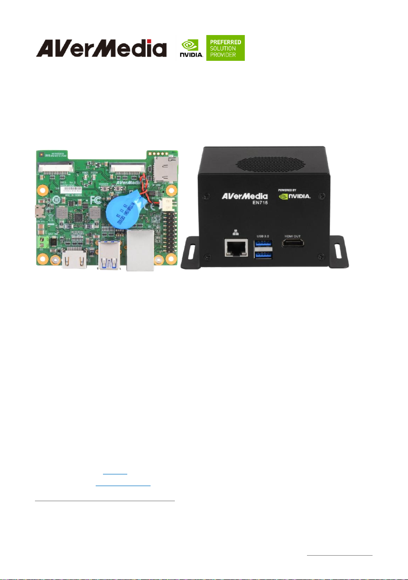
2.2 Front View and Back View of EN715_________________________________________________ 11
2.3 Front View and Three-Quarter View of EN715 BoxPC_____________________________ 12
2.4 Connector Summary___________________________________________________________________ 12
2.5 Switch Summary_______________________________________________________________________ 14
3.0 Feature Description ................................................................................................................... 15
3.1 Connector and Switch Locations _____________________________________________________ 15
3.2 SerDes (V-by-One® HS)_______________________________________________________________ 16
3.3 Jetson™ Nano/NX Module Connector _______________________________________________ 17
3.4 Fan Power connector __________________________________________________________________ 17
3.5 MIPI CSI-2 DPHY Lanes _____________________________________________________________ 18
3.6 RTC Battery Connector _______________________________________________________________ 20
3.7 OTG/USB Micro-Type Connector____________________________________________________ 20

2
EN715 User Guide AVerMedia Technologies, Inc www.avermedia.com
3.8 20-Pin GPIO expansion________________________________________________________________ 21
3.9 Power Supply Connector ______________________________________________________________ 22
3.10 Gigabit Ethernet Connector________________________________________________________ 22
3.11 USB 3.1 Gen 1 Type-A Connector #1 and #2______________________________________ 23
3.12 HDMI OUTPUT ____________________________________________________________________ 23
3.13 Optional Function Selection________________________________________________________ 24
3.14 Micro SD Card Slot_________________________________________________________________ 24
3.15 Other Switches and Jumpers_______________________________________________________ 24
4.0 Installation................................................................................................................................... 25
4.1 BSP Setup Instructions ________________________________________________________________ 25
5.0 Software........................................................................................................................................ 26
6.0 Force Recovery Mode................................................................................................................ 27
7.0 Power Consumption................................................................................................................... 28
8.0 Option Accessory Drawings...................................................................................................... 28
8.1 Power Cable, Fan Module and Adapter and Power Cord __________________________ 28
9.0 Dimension Drawings and Assembly Drawings..................................................................... 34
9.1 Dimension Drawings of EN715 _______________________________________________________ 34
9.2 Dimension Drawing of EN715 Box PC _______________________________________________ 35

3
EN715 User Guide AVerMedia Technologies, Inc www.avermedia.com
Preface
Disclaimer
The information contained in this user manual, including but not limited to any product
specification is subject to change without notice. AVerMedia assumes no liability for any
damages incurred directly or indirectly from any technical or typographical errors or omissions
contained herein or for discrepancies between the product and the user manual.
Technical Support
If you experience the difficulty after reading this manual and/or using the product, please contact
the reseller from which you purchased the product. In most cases, the reseller can help you with
the product installation and the difficulty you encountered.
In case the reseller is not able to resolve your problem, our highly capable global technical
support team can certainly assist you. Our technical support section is available 24 hours a day
and 7 days a week through our website, with the click here. For more contact information, you
may find it in the section of AVerMedia Global Offices.
Contact Enquiry
For more information of our products, pricing, and order placement, please fill in our inquiry
form here, we will contact you within 24 hours.
Download User Manual
Please click the link here to download the file of this user manual from AVerMedia website.
Revision History
Revision
Date
Updates
Version 1.0
May 15, 2020
Release user manual

4
EN715 User Guide AVerMedia Technologies, Inc www.avermedia.com
AVerMedia Global Offices

5
EN715 User Guide AVerMedia Technologies, Inc www.avermedia.com
Limited Product Warranty
AVerMedia provides the one-year product warranty. Should this product, in AVerMedia's
opinion, fail to be in the good working order during the warranty period, AVerMedia will, at its
option, repair or replace it at no charge, provided that the product has not been subjected to abuse,
misuse, accident, disaster, or non-AVerMedia authorized modification or repair.
You may obtain the warranty service by delivering this product to an authorized AVerMedia
business partner or to AVerMedia along with the proof of purchase. Product returned to
AVerMedia must be pre-authorized by AVerMedia with an RMA (Return Material Authorization)
number marked on the outside of the package and sent prepaid, insured, and packaged for the safe
shipment. AVerMedia will return the product by prepaid shipment service.
The limited product warranty is only valid over the serviceable life of the product. This is
defined as the period during which all components are available. Should the product prove to be
irreparable, AVerMedia reserves the right to substitute an equivalent product if available or to
retract the product warranty if no replacement is available.
The above product warranty is the only warranty authorized by AVerMedia. Under no
circumstances will AVerMedia be liable in any way for any damages, including any lost profits,
lost savings, or other incidental or consequential damages arising out of the use of, or inability to
use, such product.
Copyright Notice
The information contained in this document is subject to change without notice. AVerMedia shall
not be liable for errors contained herein or for incidental consequential damages in connection
with the furnishing, performance, or use of this material. This document contains proprietary
information that is protected by copyright. All rights are reserved. No part of this document may
be photocopied, reproduced, or translated to another language without the prior written consent
by AVerMedia.

6
EN715 User Guide AVerMedia Technologies, Inc www.avermedia.com
Trademark Acknowledgement
AVerMedia acknowledges all the trademarks, registered trademarks, and/or copyrights referred to
in this document as the property of their respective owners. Not listing all possible trademarks or
copyright acknowledgments does not constitute the lack of acknowledgment to the rightful
owners of the trademarks and copyrights mentioned in this document.
ESD Warning
Electronic components and circuits are sensitive to Electrostatic Discharge (ESD). When
handling any circuit board assemblies including AVerMedia AVerAI products, it is highly
recommended that ESD safety precautions can be observed. ESD safe best practices can include,
but are not limited to the following ones.
1. Leave the circuit board in the antistatic package until it is ready to be installed.
2. Use a grounded wrist strap when handling the circuit board. At a minimum, you need to touch
a grounded metal object to dissipate any static charge, which may be present on you.
3. Avoid handling the circuit board in the carpeted areas.
4. Handle the board by the edges and avoid the contact with the components.
5. Only handle the circuit boards in ESD safe areas, which may include ESD floor and/or table
mats, wrist strap stations, and ESD safe lab coats.

7
EN715 User Guide AVerMedia Technologies, Inc www.avermedia.com
1.0 Introduction
AVerMedia AVerAI EN715 includes three fully featured carrier boards and one associated Box
PC’s which is all developed for NVIDIA®Jetson NanoTM (Version B01) / Xavier™ NX modules.
AVerAI EN715 provides not only the access to a great list of latest interfaces on Xavier™ NX
modules but also one RJ-45 interface and one RTC battery as the function enrichment.
EN715 provides one 4Kp60 HDMI video output, two USB 3.0 ports, one GbE RJ-45 port,
20-pins GPIO expansion, and one Micro-B USB 2.0 port for recovery. It also comes with a
single-mold PCB terminal block module for easy power connection.
Operating with NVIDIA®Jetson NanoTM / Xavier™ NX module and the rich I/O functions,
AVerAI EN715 is the perfect choice in building a compact, high performance AI edge computing
platform for the intelligent video analytics applications.

8
EN715 User Guide AVerMedia Technologies, Inc www.avermedia.com
1.1 Product Specifications
Model
EN715-BBC3
EN715-BBC2
Compatibility
NVIDIA® Jetson Nano™ (Version B01)/Xavier™ NX module
Networking
1x GbE RJ-45
Display Output
3840 x 2160 at 60Hz
Temperature
Operating temperature 0°C~70°C
Storage temperature -40°C ~ 85°C
Relative humidity 40 °C @ 95%, Non-Condensing
MIPI Camera
Inputs
-2x 2 lane MIPI CSI-2, 15 pin FPC
1mm Pitch Connector
-1x 4 Lane MIPI CSI-2, 36 pin FPC
1mm Pitch Connector
-2x 2 lane MIPI CSI-2, 15 pin FPC
1mm Pitch Connector
USB
1x USB 2.0 Micro-B for recovery
2x USB 3.0 Type-A
Storage
1x micro-SD card slot
GPIO Expansion
20 pins: 2x I2C, 1x UART, 9x GPIOs
Input Power
3.5mm Screw Terminal; 9V~19V is recommended.
Buttons
Power and Recovery
RTC Battery
Support RTC battery and Battery Life Monitoring by MCU
Dimension/ Weight
W: 87mm x L: 70.6mm x H: 27.3mm (3.43” x 2.78” x 1.07”), Weight: 70g
Accessory
DC Jack Power Extension Cable (5.5 x 2.5mm x 30cm)
Certifications
CE, FCC, KC

9
EN715 User Guide AVerMedia Technologies, Inc www.avermedia.com
1.2 OPTION ACCESSORY
Item
EN715-BBC3
EN715-BBC2
NVIDIA® Jetson
Nano™ (Version B01) / Xavier NX
Fan Module
-Heat sink with Fan (Dimension: 56 x 40.8 x 20 mm) for Jetson Nano™
(Version B01)
-Heat sink with Fan (Dimension: 59 x 40.8 x 30 mm) for Xavier™ NX
module
AC Adaptor
12V, 5A
Power cord
EU/JP/TW/US/CN/UK
MIPI Camera
Camera Module Manufacturer: APPRO.PHO
–For 15 pin MIPI connector
B-04: IMX179(8M)MIPI, 1080P(30fps)
C-04: IMX290(2M)MIPI, 1080P(30fps)
C-05: IMX290(2M)+ISP(YUV), 1080P(30fps)
–For 36 pin MIPI connector
B-03: IMX334(4K) MIPI, 4K(30/60fps)
B-13: IMX334(4K)+ISP(YUV) , 4K(30fps)
A-03: IMX290(FHD) V-by-One® HS, 1080P(60fps)
A-06: IMX334(4K) V-by-One® HS x1, 4K(30fps)

10
EN715 User Guide AVerMedia Technologies, Inc www.avermedia.com
2.0 Product Overview
2.1 Block Diagram

11
EN715 User Guide AVerMedia Technologies, Inc www.avermedia.com
2.2 Front View and Back View of EN715

12
EN715 User Guide AVerMedia Technologies, Inc www.avermedia.com
2.3 Front View and Three-Quarter View of EN715 BoxPC
2.4 Connector Summary

13
EN715 User Guide AVerMedia Technologies, Inc www.avermedia.com
PCB Code
Designation
Description
EN715-BBC2
J1
N/A
J2
SO-DIMM socket for NVIDIA®Jetson Nano™ and
Jetson™XavierNX module
J3
Fan Power connector
J4
2 Lane MIPI CSI-2 camera connector
J5
2 Lane MIPI CSI-2 camera connector
J6
RTC battery connector
J7
USB 2.0 Micro-B
J8
20-pin GPIO expansion
J9
Power connector
J10
Gigabit Ethernet connector
J11
USB 3.1 Gen 1 Type-A connectors
J12
HDMI 2.0 connector
J13
Micro SD card slot

14
EN715 User Guide AVerMedia Technologies, Inc www.avermedia.com
PCB Code
Designation
Description
EN715-BBC3
J1
4 Lane MIPI CSI-2 camera connector
J2
SO-DIMM socket for NVIDIA®Jetson Nano™ and
Jetson™XavierNX module
J3
Fan Power connector
J4
2 Lane MIPI CSI-2 camera connector
J5
2 Lane MIPI CSI-2 camera connector
J6
RTC battery connector
J7
USB 2.0 Micro-B
J8
20-pin GPIO expansion
J9
Power connector
J10
Gigabit Ethernet connector
J11
USB 3.1 Gen 1 Type-A connectors
J12
HDMI 2.0 connector
J13
Micro SD card slot
2.5 Switch Summary
Designation
Description
SW3
RECOVERY button
SW4
POWER on button
SW5
Fan PWM controller/Auto Power on

15
EN715 User Guide AVerMedia Technologies, Inc www.avermedia.com
3.0 Feature Description
3.1 Connector and Switch Locations
J3
J1
J2
J6
J10
J5
J4
J11
J8
J12
J7
J9
SW5
5
J13
SW3
SW4
SW3

16
EN715 User Guide AVerMedia Technologies, Inc www.avermedia.com
3.2 SerDes (V-by-One® HS)
Function
MIPI camera module connector
Location
J1
Type Description
WAFER_1*36PIN_0.5㎜_180°
Manufacturer and
Part Number
PINREX 979-44-93610A_ZIF FPC
Mating Connector
4 Lane MIPI CSI-2 camera connector (36PIN)
PIN OUT

17
EN715 User Guide AVerMedia Technologies, Inc www.avermedia.com
3.3 Jetson™ Nano/NX Module Connector
Function
Provide connection with NVIDIA® Jetson
Nano™ / Xavier™ NX
Location
J2
Type Description
SOCKET_DDR4
SO-DIMM_260PIN_90°
Manufacturer
and Part Number
Foxconn ASAA826-EASB0-7H
Mating
Connector
NVIDIA® Jetson Nano™(Version B01) /
Xavier™ NX module
Pinout
Please refer to NVIDIA Jetson Nano™ /
Xavier™ NX and AGX Xavier™
System-on-Module datasheet for pinout
details.
Remarks
https://developer.nvidia.com/ embedded/downloads
3.4 Fan Power connector
Function
Fan Power Connector
Location
J3
Type Description
WAFER_1*4PIN_1.25㎜_90°
Manufacturer
and Part Number
ACES 50271-0040N-001_BLACK
Pinout
Pin #
Description
PIN 1
GND
PIN 2
Power +5V
PIN 3
FAN_TACH
PIN 4
FAN_PWM
Remarks
None

18
EN715 User Guide AVerMedia Technologies, Inc www.avermedia.com
3.5 MIPI CSI-2 DPHY Lanes
Function
MIPI camera module connector
Location
J4 , J5
Type
Description
WAFER_15PIN_1㎜_90°
Manufacture
r and Part
Number
CHAMPWAY AFA07-S15FCA-HF_FPC
ZIF-LOWER
Mating
Connector
2 Lane MIPI CSI-2 camera connector (15Pin)
Pinout
J4
PIN#
Description
PIN#
Description
Pin1
GND
Pin9
CSI0_CLK_P
Pin2
CSI0_D0_N
Pin10
GND
Pin3
CSI0_D0_P
Pin11
MIPI2_PWDN
Pin4
GND
Pin12
CAM2_MCLK
Pin5
CSI0_D1_N
Pin13
CSI0_I2C_SCL
Pin6
CSI0_D1_P
Pin14
CSI0_I2C_SDA
Pin7
GND
Pin15
+3V3_MIPI
Pin8
CSI0_CLK_N

19
EN715 User Guide AVerMedia Technologies, Inc www.avermedia.com
J5
PIN#
Description
PIN#
Description
Pin1
GND
Pin9
CSI2_CLK_P
Pin2
CSI2_D0_N
Pin10
GND
Pin3
CSI2_D0_P
Pin11
MIPI2_PWDN
Pin4
GND
Pin12
CAM2_MCLK
Pin5
CSI2_D1_N
Pin13
CSI2_I2C_SCL
Pin6
CSI2_D1_P
Pin14
CSI2_I2C_SDA
Pin7
GND
Pin15
+3V3_MIPI
Pin8
CSI2_CLK_N
Other manuals for AVerAI EN715
1
This manual suits for next models
2
Table of contents
Other Avermedia Carrier Board manuals

Avermedia
Avermedia D131ONB User manual

Avermedia
Avermedia D131 Series User manual

Avermedia
Avermedia AVerAI EN715 User manual

Avermedia
Avermedia AVerAI EN713-AAE9 User manual

Avermedia
Avermedia AVerAI NO111B User manual

Avermedia
Avermedia EX713AA User manual

Avermedia
Avermedia TN111B User manual

Avermedia
Avermedia AVerAI AG411 User manual