manuals.online logo
Brands
  1. Home
  2. •
  3. Brands
  4. •
  5. Avery Weigh-Tronix
  6. •
  7. Accessories
  8. •
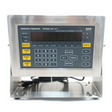
  9. Avery Weigh-Tronix WI-127 User manual

Avery Weigh-Tronix WI-127 User manual

1
Monorail Installation Guide
This guide is a step by step procedure for installing a Weigh-Tronix monorail
scale. Before you attempt any of these procedures, we urge you to read
through the entire guide so you can familiarize yourself with what needs to
be done.
Locate the point in the existing monorail system where the weighing unit is
to be installed and route the interface cables to that location. Refer to Figure
1 and proceed as follows:
1. Remove a section of existing monorail equal to the total length of the
weighing unit and support the ends with rail hangers.
2. Drill holes in the dead rails and mount the weighing unit in place using
standard rail hangers.
3. Angle iron or similar bracing material can be attached to the back frame
of the unit for additional support and to eliminate vibration.
4. Adjust the weighing unit so it is level both lengthwise and from front to
back. A level can be placed on top of the back frame to check the
levelness of the unit.
5. Connect the indicator interface cable to J1 on the junction box. On the
in-motion model, see Figure 1, connect the control cable to the limit
switch. Interface cables should be routed and secured so they will not
be pinched, cut or snagged by monorail operations.
Installation
Introduction
Figure 1
Static monorail scale In-motion monorail scale
2
Do not use the predrilled holes
in the ends of the frame for
mounting the unit; these holes
are provided for removing the
Weigh Bar roll pins.
Weight Sensor Balance
Adjustment
Weigh Bar Replacement If it becomes necessary to replace a Weigh Bar, follow these steps:
1. Remove the two socket head screws that hold the live rail to the Weigh
Bars and remove the live rail.
2. Disconnect the Weigh Bar cable from the junction box and remove the
cable clamp from the frame.
3. Drive the roll pin out of the Weigh Bar mount with a 3/16 inch drift punch
inserted through the hole in the end frame.
4. Remove the defective Weigh Bar.
5. Insert the replacement Weigh Bar in the frame mount, making sure the
top of the Weigh Bar is up. The top is marked with a “T” on the Weigh
Bar shaft near the roll pin hole.
6. Align the hole in the Weigh Bar with the hole in the frame and insert the
roll pin.
7. Connect the Weigh Bar cable to the junction box and secure the cable
clamp.
8. Mount the live rail to the Weigh Bars.
This scale uses a junction box (J-box) where the outputs of two weight
sensors of matching capacities are added together. The J-box then sends a
single weight signal to the indicator. These multiple signals must be bal-
anced for the scale to function properly. This is done at the factory, but
these instructions are provided in case you ever need them. Because the
balance adjustment of one weigh sensor affects the adjustment of the other
weight sensor, always recheck both adjustments. Figure 2 illustrates the
type of J-box in the conveyor scale. Potentiometer R2 affects one weight
sensor and R3 affects the other. R1 is the zero adjust potentiometer for
deadload offset.
Figure 2
J-box
3
Balance the weight sensors by adjusting potentiometers in the j-box, as
follows:
1. Remove the j-box cover to access the potentiometers.
2. Zero the indicator with an empty trolley on the monorail.
3. Place a minimum of 25% of capacity using calibrated test weight on the
trolley and place the trolley directly over one of the weight sensors.
4. Record displayed weight value.
5.. Completely remove test weight and verify the display returns to zero
before reloading above the other weight sensor.
6. Repeat Steps 3 through 5 for the other weight sensor.
7. If displayed weight value for a weight sensor varies from the other by
less than ±1 division, proceed now to appropriate service manual with
the calibration instructions for the indicator being used.
8. If displayed weight value for any weight sensor varies from the others by
more than ±1 division, adjust j-box potentiometers by turning them the
number of 360° turns indicated by this formula:
If Number of Turns is positive value, turn potentiometer clockwise. If
Number of Turns is a negative value, turn potentiometer counterclockwise.
9. Repeat Steps 3 through 8 until all weight sensors are equal, within ±1
scale division and proceed to appropriate service manual with the
calibration instructions for the indicator being used.
4
Setpoint #1 is the start averaging input
Setpoint #2 is the stop averaging input
Setpoint #3 is the accept output (optional)
Setpoint #4 is the reject output (optional)
Showvar displays the weight to the screen.
WT is the variable that the average weight is stored in and used for display
and accept/reject purposes.
Setpoint 1 is the minimum acceptable value.
Setpoint 2 is the maximum acceptable value.
The F1 key is used to set the min and max values.
When setpoint #1 (ie. entrance sensor) is triggered by the trolley, the WI-
130 begins averaging and turns off both accept and reject outputs.
When the trolley triggers setpoint #2 (ie. exit sensor) the WI-130 stops
averaging, displays the average weight on the scale, and at that time the
accept and reject output are turned on or off according to the values entered
using the F1 key.
This section is optional. It refers to using an Accept/Reject device control.
Set SW1 1,2,& 3 to ON position.
Install output OPTO 22 modules in J40, J41 on I/O expansion board.
SIGNAL I/O BRD WI-130 MAIN BRD
SCL TB35-1 TB5-1
SDA TB35-2 TB5-2
IICINT TB35-3 TB5-3
GND TB35-4 TB5-4
+5V TB35-5 TB5-5
RESET TB35-6 TB5-6
SHIELD TB35-7 TB5-7
Information for WI-130 User’s
8587A Photocell I/0
Installation
Configuration
Operation
SSCU-8 Remote
Expanded I/O
Configuration
Setpoints
5
WI-130 Main Board I/O
Configuration
Entrance and Exit
Sensor Connections
Install input OPTO 22 modules in J22, J23 on WI-130 main board.
On earlier revision main boards
you may use +5vdc from a
serial connector instead of
+12vdc.
6
WI-127 In-Motion wiring
Information for WI-127 User’s
The wiring information to connect a WI-127 indicator to a conveyor scale is
shown below as is a sketch of the connection.
Wire Color WI-127 Function
White TB15-8 Set input (exit trigger)
Black TB15-9 Logic Gnd
Red TB15-7 Reset input (entrance trigger)
Shield Chassis Shield
7
Information for WI-110 and WI-120 User’s
Connection of the external print switch will disable any print request from the
printer but the DATA SEND key on the weight indicator will remain active.
The WI-110 must meet the following criteria for installation of an external
serial print switch:
1. It must be equipped with software version V5.5 S8.0 or later.
2. It must be equipped with A-5 serial interface PC card, PN19496-0027,
Revision E or later. R18 must be removed, the PC foil should be cut
between U3 pin 10 and J3 pin 6. A jumper should be installed between
J3 pin 6 and U7 pin 3.
3. In watertight enclosures, connect the print switches to TB201 on the A-
15 Serial Interconnect PC card (PN19544-0011) as shown in Figure 3.
4. In desktop enclosures, adapter cable PN20336-0011, Revision A)
should be used to provide connection points for the print switch. The
interconnect cable wires connect to the same color wires on the adapter
cable pigtail.
Figure 3
To connect an external print switch to a WI-110 indicator that is not
equipped with software version V5.5 S8.0 or later, contact the Weigh-Tronix
Service Department.
In-Motion Print Switch
Connections
Weigh Bar®is a registered trademark of Weigh-Tronix Inc.
11/29/99 MONO_i.P65 PN 16759-0017e1 Printed in USA
Weigh-Tronix
1000 Armstrong Dr.
Fairmont, MN 56031 USA
Telephone: 507-238-4461
Facsimile: 507-238-4195
e-mail: [email protected]
www.weigh-tronix.com
Weigh-Tronix Canada, ULC
217 Brunswick Blvd.
Pointe Claire, QC H9R 4R7 Canada
Telephone: 514-695-0380
Facsimile: 514-695-6820
Weighing Products & Systems

Other manuals for WI-127

2

This manual suits for next models

2

Other Avery Weigh-Tronix Accessories manuals
Avery Weigh-Tronix WI-150 User manual

Avery Weigh-Tronix

Avery Weigh-Tronix WI-150 User manual

Avery Weigh-Tronix ZM201 User manual

Avery Weigh-Tronix

Avery Weigh-Tronix ZM201 User manual

Avery Weigh-Tronix WI-127 User manual

Avery Weigh-Tronix

Avery Weigh-Tronix WI-127 User manual

Avery Weigh-Tronix 1310 User manual

Avery Weigh-Tronix

Avery Weigh-Tronix 1310 User manual

Avery Weigh-Tronix 640 Series Operating instructions

Avery Weigh-Tronix

Avery Weigh-Tronix 640 Series Operating instructions

Avery Weigh-Tronix 915A User manual

Avery Weigh-Tronix

Avery Weigh-Tronix 915A User manual
Avery Weigh-Tronix ZM615 User manual

Avery Weigh-Tronix

Avery Weigh-Tronix ZM615 User manual

Avery Weigh-Tronix ZM505 User manual

Avery Weigh-Tronix

Avery Weigh-Tronix ZM505 User manual

Avery Weigh-Tronix ZM401 User manual

Avery Weigh-Tronix

Avery Weigh-Tronix ZM401 User manual

Avery Weigh-Tronix 2060 User manual

Avery Weigh-Tronix

Avery Weigh-Tronix 2060 User manual

Avery Weigh-Tronix ZM605 User manual

Avery Weigh-Tronix

Avery Weigh-Tronix ZM605 User manual

Avery Weigh-Tronix ZK830 User manual

Avery Weigh-Tronix

Avery Weigh-Tronix ZK830 User manual

Avery Weigh-Tronix 640XL User manual

Avery Weigh-Tronix

Avery Weigh-Tronix 640XL User manual

Avery Weigh-Tronix ZM510 User manual

Avery Weigh-Tronix

Avery Weigh-Tronix ZM510 User manual

Avery Weigh-Tronix WI-127 User manual

Avery Weigh-Tronix

Avery Weigh-Tronix WI-127 User manual

Avery Weigh-Tronix WI-125 SST User manual

Avery Weigh-Tronix

Avery Weigh-Tronix WI-125 SST User manual

Avery Weigh-Tronix 1080 User manual

Avery Weigh-Tronix

Avery Weigh-Tronix 1080 User manual

Avery Weigh-Tronix E1010 User manual

Avery Weigh-Tronix

Avery Weigh-Tronix E1010 User manual
Avery Weigh-Tronix ZM510 User manual

Avery Weigh-Tronix

Avery Weigh-Tronix ZM510 User manual
Popular Accessories manuals by other brands

Rice Lake Revolution SURVIVOR 420HE installation manual

Rice Lake

Rice Lake Revolution SURVIVOR 420HE installation manual

Sunbeam Sleep Perfect Instruction booklet

Sunbeam

Sunbeam Sleep Perfect Instruction booklet

PCB Piezotronics HT354C03 Installation and operating manual

PCB Piezotronics

PCB Piezotronics HT354C03 Installation and operating manual

Aritech 2000 Series Installation & service instructions

Aritech

Aritech 2000 Series Installation & service instructions

HPM 630/3 instruction manual

HPM

HPM 630/3 instruction manual

Byron DB333 Installation and operation instruction

Byron

Byron DB333 Installation and operation instruction

EMT 909-HI user manual

EMT

EMT 909-HI user manual

PHYWE Cobra SMARTsense Acceleration operating instructions

PHYWE

PHYWE Cobra SMARTsense Acceleration operating instructions

Philips HQ55/3P Replacement guide

Philips

Philips HQ55/3P Replacement guide

Obelink VERONA PITCHING INSTRUCTION

Obelink

Obelink VERONA PITCHING INSTRUCTION

RaidSonic ICY BOX IB-PBb10400 manual

RaidSonic

RaidSonic ICY BOX IB-PBb10400 manual

Panasonic SC-GU1-485 instruction manual

Panasonic

Panasonic SC-GU1-485 instruction manual

System Sensor 5551 Installation and maintenance instructions

System Sensor

System Sensor 5551 Installation and maintenance instructions

Linsar DUB1UK instruction manual

Linsar

Linsar DUB1UK instruction manual

Cooluli INFINITY-10L instruction manual

Cooluli

Cooluli INFINITY-10L instruction manual

Zublin Swiss Garde 360 Premium 25050 user manual

Zublin

Zublin Swiss Garde 360 Premium 25050 user manual

ROSE DISPLAYS SUPERSNAP WITH MULTICLIPS instruction sheet

ROSE DISPLAYS

ROSE DISPLAYS SUPERSNAP WITH MULTICLIPS instruction sheet

YEAZ TWEAK-X instruction manual

YEAZ

YEAZ TWEAK-X instruction manual

manuals.online logo
manuals.online logoBrands
  • About & Mission
  • Contact us
  • Privacy Policy
  • Terms and Conditions

Copyright 2025 Manuals.Online. All Rights Reserved.