manuals.online logo
Brands
  1. Home
  2. •
  3. Brands
  4. •
  5. System Sensor
  6. •
  7. Accessories
  8. •
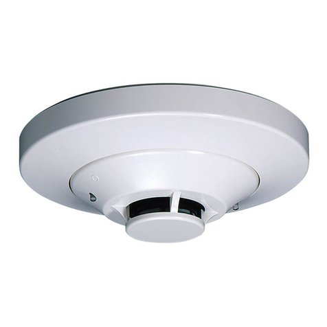
  9. System Sensor 5551 User manual

System Sensor 5551 User manual

D550-05-00 1 I56-336-06
Specifications
Diameter: 6.1 inches (15.5 cm) installed in B501B
4.1 inches (10.4 cm) installed in B501
Height: 1.6 inches (4.1 cm)
Weight: 5 ounces (150 g)
Installation Temperatures: 32°to 100°F
Operating Temperature Range: 0°to 38°C (32°to 100°F)
Operating Humidity Range: 10% to 93% Relative Humidity
Mounting: B501B flanged base
B501 flangeless base
B501 with RMK recessed mounting kit
Voltage Range: 15 to 32 Volts DC Peak
Standby Current: 200
µ
A @ 24 VDC
LED Current: 7 mA @ 24 VDC
Fixed Temperature Thermal: 135°F (57°C)
5551 Plug-in Intelligent
Fixed Temperature Sensor
with Communications
INSTALLATION AND MAINTENANCE INSTRUCTIONS
Before Installing
Please thoroughly read the system wiring and installation
manual, which provides detailed information on sensor
spacing, placement, zoning, and special applications. Cop-
ies of these manuals are available from System Sensor.
NOTICE: This manual should be left with the owner/user
of this equipment.
IMPORTANT: This sensor must be tested and maintained
regularly following NFPA 72 requirements. This sensor
should be cleaned at least once a year.
General Description
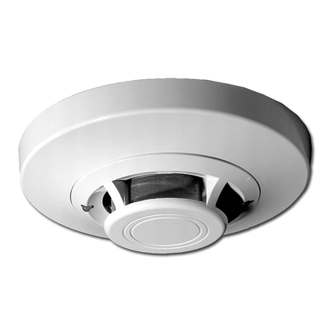
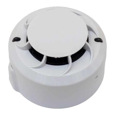
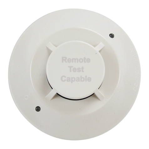
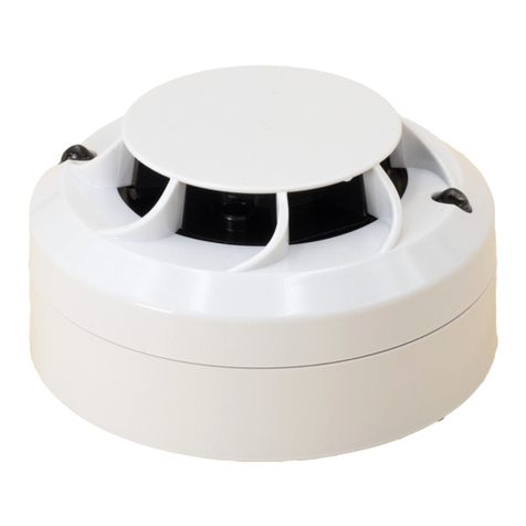
The model 5551 is a fixed temperature intelligent sensor
utilizing a state-of-the-art dual thermistor sensing circuit
for fast response. These sensors are designed to provide
open area protection with 50 foot spacing capability, and
are to be used with compatible control panels only. (For in-
stallation in Canada, refer to ULC-S530-1978.)
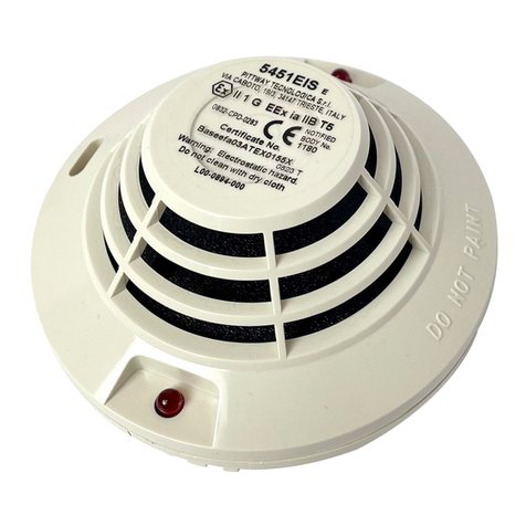
Two LEDs on each sensor light to provide 360°visibility of
the sensor indication. The LEDs can be latched ON by code
command from the panel for an alarm indication. The
LEDs can also be unlatched to the normal condition by
code command. Remote LED annunciator capability is
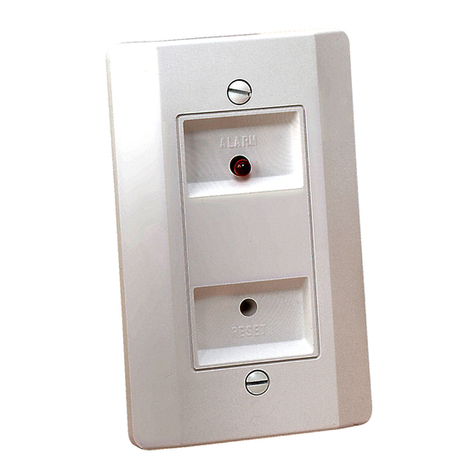
available as an optional accessory (Part No. RA400).
A Division of Pittway
3825 Ohio Avenue, St. Charles, Illinois 60174
1-800-SENSOR2, FAX: 630-377-6495
32
1
32
1
32
1
+
-
-
+
U.L. LISTED COMPATIBLE
CONTROL PANEL
CLASS A OPTIONAL WIRING
REMOTE ANNUNCIATOR
+- CAUTION: Do not loop wire under terminal 1 or 2.
Break wire run to provide supervision of connections.
Wiring Guide
Refer to the installation instrucitons for the particular plug-
in base being used: 1) for the B501B base (D550-01-01); 2)
for the B501 base (D550-02-00); 3) for the RMK400 used
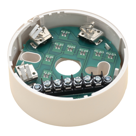
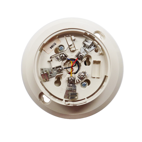
with the B501 base (D450-07-00). Bases are provided with
screw terminals for power, ground, and remote annunciator
connections.
NOTE: All wiring must conform to applicable local codes,
ordinances, and regulations.
NOTE: Verify that all Sensor Bases are installed and that
the wiring polarity is correct at each base.
WARNING
Remove power from the loop before installing sensors.
1. Install Sensors:
a. Verify that the sensor type matches the type written
on the label in the base.
b. Set the sensor to a desired address and then write the
address on the label on the base.
c. Place the sensor into the sensor base.
d. Turn the sensor clockwise until it drops into place.
e. Continue turning the sensor clockwise to lock it in
place.
2. Tamper-proof feature:
The sensor bases include a tamper-proof feature that,
when activated, prevents removal of the sensor without
the use of a tool. See the installation instruction manual
for the sensor base for details in using this feature.
D550-05-00 2 I56-336-06
A78-1253-01
Figure 1. Wiring diagram:
3. After all sensors have been installed, apply power to the
control unit.
4. Test the sensor by placing a small magnet against the
sensor plastic directly opposite the test meter socket
(Figure 2). The alarm level will be recognized in the
panel and the LED controlled by communication com-
mand from the panel.
5. The reset of the sensor LED is controlled by communica-
tion command from the panel.
Testing the 5551 Sensitivity
Sensors must be tested after installation and periodic main-
tenance. The sensitivity of the 5551 may be tested in the
two following ways.
A. Test Magnet (Model No. M02-04)
1. Place the magnet against the cover opposite the test
module slot as shown in Figure 2 to activate the test
feature.
2. The LEDs should latch ON within 10 seconds, indicat-
ing alarm and annunciating the panel.
B. Test sensitivity from the control panel.
Cleaning the Model 5551 Sensor
NOTE: Before cleaning, notify the proper authorities that
the system is undergoing maintenance, and therefore the
system will temporarily be out of service. Disable the loop
or system undergoing maintenance to prevent unwanted
alarms.
It is recommended that the sensor be removed from its
mounting base for easier cleaning, and that sensors be
cleaned at least once a year. Use a vacuum cleaner to re-
move dust from the sensing chamber.
D550-05-00 3 I56-336-06
A78-1944-00
Figure 3:
Figure 2. Views showing position of test magnet:
TEST
MAGNET
LED
TEST MODULE
SOCKET
LED
PAINTED
SURFACE
TEST
MAGNET
A78-1478-00
D550-05-00 4 I56-336-06
© System Sensor 1996
Three-Year Limited Warranty
System Sensor warrants its enclosed heat detector to be free from defects
in materials and workmanship under normal use and service for a period
of three years from date of manufacture. System Sensor makes no other
express warranty for this heat detector. No agent, representative, dealer, or
employee of the Company has the authority to increase or alter the obliga-
tions or limitations of this Warranty. The Company’s obligation of this
Warranty shall be limited to the repair or replacement of any part of the
heat detector which is found to be defective in materials or workmanship
under normal use and service during the three year period commencing
with the date of manufacture. After phoning System Sensor’s toll free
number 800-SENSOR2 (736-7672) for a Return Authorization number,
send defective units postage prepaid to: System Sensor, Repair Depart-
ment, RA #__________, 3825 Ohio Avenue, St. Charles, IL 60174. Please
include a note describing the malfunction and suspected cause of failure.
The Company shall not be obligated to repair or replace units which are
found to be defective because of damage, unreasonable use, modifica-
tions, or alterations occurring after the date of manufacture. In no case
shall the Company be liable for any consequential or incidental damages
for breach of this or any other Warranty, expressed or implied whatsoever,
even if the loss or damage is caused by the Company’s negligence or fault.
Some states do not allow the exclusion or limitation of incidental or conse-
quential damages, so the above limitation or exclusion may not apply to
you. This Warranty gives you specific legal rights, and you may also have
other rights which vary from state to state.
WARNING
The Limitations of Property Protection Heat Detectors
Heat detectors do not always detect fires because the fire may be a
slow-smoldering, low-heat type (producing smoke), or because they
may not be near where the fire occurs, or because the heat of the fire
may bypass them. Heat detectors will not detect smoke, gas, flames, or
combustion particles.
Heat detectors are components in professionally installed fire alarm
systems. They will not function if they have been improperly wired
into the fire alarm system or if power to them is cut off for any reason.
Heat detectors cannot last forever. They should be tested and maintained
following the instructions in this manual. To be safe, they should be
replaced after they have been installed for 15 years.
Refer to NFPA 72 for application.
This heat detector is designed to activate and initiate emergency action,
but will do so only when it is used in conjunction with an authorized fire
alarm system. This detector must be installed in accordance with NFPA
standard 72.
Heat detectors will not work without power. AC or DC powered smoke
detectors will not work if the power supply is cut off for any reason.
Heat detectors are designed to protect property, not life. They do not
provide early warning of fire and cannot detect smoke, gas, combustion
particles, or flame. They alarm when temperatures at the heat detector
reach 57°C (135°F). Given the rapid growth of certain types of fires, heat
detectors cannot be expected to provide adequate warning of fires
resulting from smoking in bed, inadequate fire protection practices,
violent explosions, escaping gas, improper storage of flammable liquids
like cleaning solvents, other safety hazards, or arson.
Other System Sensor Accessories manuals

System Sensor B401BH User manual

System Sensor

System Sensor B401BH User manual

System Sensor 22051E User manual

System Sensor

System Sensor 22051E User manual

System Sensor 2551HR User manual

System Sensor

System Sensor 2551HR User manual

System Sensor 2251TEM User manual

System Sensor

System Sensor 2251TEM User manual

System Sensor 2351TIR User manual

System Sensor

System Sensor 2351TIR User manual

System Sensor 2251BR User manual

System Sensor

System Sensor 2251BR User manual

System Sensor B200SR User manual

System Sensor

System Sensor B200SR User manual

System Sensor 7251 User manual

System Sensor

System Sensor 7251 User manual

System Sensor RTS451 User manual

System Sensor

System Sensor RTS451 User manual

System Sensor 2251TM User manual

System Sensor

System Sensor 2251TM User manual

System Sensor SMB500 User manual

System Sensor

System Sensor SMB500 User manual

System Sensor 72051EI User manual

System Sensor

System Sensor 72051EI User manual

System Sensor 2351PTIRAUS User manual

System Sensor

System Sensor 2351PTIRAUS User manual

System Sensor 200 Series User manual

System Sensor

System Sensor 200 Series User manual

System Sensor 5251RB-WP User manual

System Sensor

System Sensor 5251RB-WP User manual

System Sensor SENS-RDR User manual

System Sensor

System Sensor SENS-RDR User manual

System Sensor B401BH User manual

System Sensor

System Sensor B401BH User manual

System Sensor B501AP-IV User manual

System Sensor

System Sensor B501AP-IV User manual

System Sensor 7351 User manual

System Sensor

System Sensor 7351 User manual

System Sensor 22051E-RF User manual

System Sensor

System Sensor 22051E-RF User manual

System Sensor SPECTR Alert ADVANCE CHSR User manual

System Sensor

System Sensor SPECTR Alert ADVANCE CHSR User manual

System Sensor 2251CTLE User manual

System Sensor

System Sensor 2251CTLE User manual

System Sensor 22051TLE User manual

System Sensor

System Sensor 22051TLE User manual

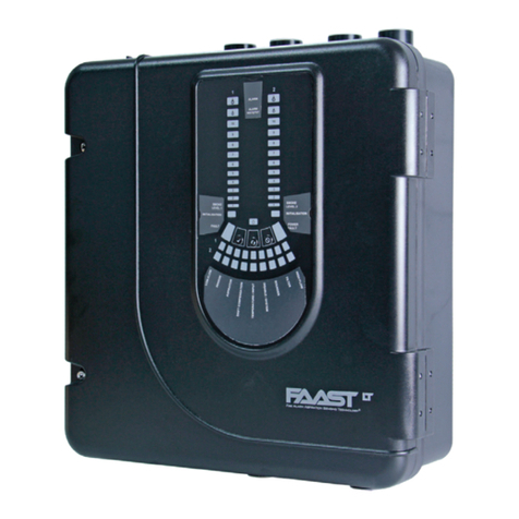
System Sensor FAAST LT User manual

System Sensor

System Sensor FAAST LT User manual

Popular Accessories manuals by other brands

KREZ Falco user manual

KREZ

KREZ Falco user manual

DeWalt DW085 Original instructions

DeWalt

DeWalt DW085 Original instructions

TP-Link HS100 quick start guide

TP-Link

TP-Link HS100 quick start guide

Clas Ohlson HTD23720 instruction manual

Clas Ohlson

Clas Ohlson HTD23720 instruction manual

Pilz PSEN ma1.1p-10 operating manual

Pilz

Pilz PSEN ma1.1p-10 operating manual

ORION TELESCOPES & BINOCULARS 10144 instruction manual

ORION TELESCOPES & BINOCULARS

ORION TELESCOPES & BINOCULARS 10144 instruction manual

LAUREN WOSW installation guide

LAUREN

LAUREN WOSW installation guide

sauter EGQ222F931 Operating Instructions, Mounting & Installation

sauter

sauter EGQ222F931 Operating Instructions, Mounting & Installation

Fetco EXTRACTOR CBS-2031e Technical bulletin

Fetco

Fetco EXTRACTOR CBS-2031e Technical bulletin

Bloomy Lotus Bamboo user manual

Bloomy Lotus

Bloomy Lotus Bamboo user manual

Honeywell Home DC313 HGP2/BS Series manual

Honeywell Home

Honeywell Home DC313 HGP2/BS Series manual

COMSOL PBF10NY user manual

COMSOL

COMSOL PBF10NY user manual

Bilanciai D70ES Use and maintenance manual

Bilanciai

Bilanciai D70ES Use and maintenance manual

Refle LS901 instruction manual

Refle

Refle LS901 instruction manual

Koolatron Auto Guard Directions for use

Koolatron

Koolatron Auto Guard Directions for use

Vermont Castings 20011992 installation instructions

Vermont Castings

Vermont Castings 20011992 installation instructions

Bosisto's AMBIENCE user manual

Bosisto's

Bosisto's AMBIENCE user manual

ESYLUX PD-FLAT 360i/8 KNX Series user manual

ESYLUX

ESYLUX PD-FLAT 360i/8 KNX Series user manual

manuals.online logo
manuals.online logoBrands
  • About & Mission
  • Contact us
  • Privacy Policy
  • Terms and Conditions

Copyright 2025 Manuals.Online. All Rights Reserved.