AVGear AVG-HD600 User manual

AVG-HD600
The AVG-HD600 is a 4K ultra-thin HDMI2.0
extender set consisting of a Transmitter and a
Receiver. It can extend 4K HDMI signals of
3840x2160@60Hz 4:4:4 (max) up to 100m via
Cat5e/6 cable. It also features a built in Ethernet
switch to extend your LAN throughout the
project.
Features
▪Supports HDMI2.0 3840x2160@60Hz
4:4:4, HDR.
▪HDCP2.2 pass-through.
▪Extends 3840x2160@60Hz 4:4:4
(Max) signal up to 100m.
▪Supports bi-directional IR and RS232
pass-through.
▪Supports bi-directional 24V PoC.
▪Built in Ethernet Switch.
▪Ultra-thin design.
▪LED indicators.

AVG-HD600
PLEASE READ THIS PRODUCT MANUAL CAREFULLY
BEFORE USING THIS PRODUCT.
This manual is only for operational instruction only,
and is not to be used in a maintenance capacity. The
functions described in this version are current as at
June 2018. Any changes of functions and operational
parameters will be updated in future manual versions.
Please refer to your dealer for the latest product
details.
Version 1.0 12/06/18

AVG-HD600
SAFETY OPERATION GUIDE
In order to guarantee the reliable operation of the equipment and safety of the
user, please abide by the following procedures during installation, use and
maintenance:
1. The system must be earthed properly. Please do not use two blade plugs
and ensure the AC power supply ranges from 100v to 240v and from 50Hz
to 60Hz.
2. Do not install the units in an environment where they will be exposed to
extreme hot or cold temperatures.
3. These units will generate heat during operation, please ensure that you allow
adequate ventilation to ensure reliable operation.
4. Please disconnect the units from mains power if they will be left unused for a
long time.
5. Please DO NOT try to open the casing of the equipment, DO NOT attempt to
repair the unit. Opening the unit will void the warranty. There are high
voltage components in the unit and attempting to repair the unit could result
in serious injury.
6. Do not allow the unit to come into contact with any liquid as that could result
in personal injury and product failure.

AVG-HD600
TABLE OF CONTENTS
Introduction..............................................................................................................1
Introduction to the AVG-HD600 ...................................................................1.1
Features.......................................................................................................1.2
What’s in the Box........ ……………………………………………………………………2
Product Appearance of the AVG-HD600 ...............................................................3
Transmitter....................................................................................................3.1
Receiver........................................................................................................3.2
System Connection .................................................................................................4
Usage Precautions....................................................................................... 4.1
Connection Diagram ....................................................................................4.2
Connection Procedure.................................................................................. 4.3
Application ....................................................................................................4.4
Specifications...........................................................................................................5
Panel Drawing..........................................................................................................6
Troubleshooting & Maintenance ............................................................................7

AVG-HD600
1. Introduction
1.1. Introduction to the AVG-HD600
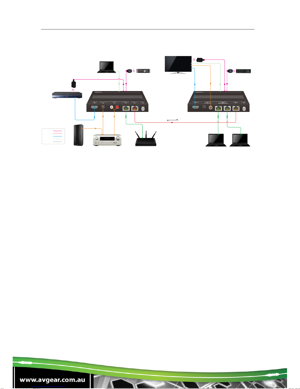
The AVG-HD600 is an ultra-thin HDMI2.0 extender set consisting of a Transmitter and a
Receiver. It can extend 3840x2160@60Hz 4:4:4 (max) HDMI signals up to 100m via Cat5e/6
cable.
Flexible power design (24V PoC) allows this extender to be powered at either the Transmitter
or the Receiver end.
It also features a built in Ethernet switch to extend the LAN throughout the project.
The bidirectional wideband IR and bidirectional RS232 make this extender compatible with
most control systems. The AVG-HD600 also supports ARC.
1.2. Features
▪Ultra-thin design.
▪Supports HDMI2.0 3840x2160@60Hz 4:4:4, HDR.
▪HDCP2.2 pass-through.
▪Extends 3840x2160@60Hz 4:4:4 (Max) signal up to 100m.
▪Supports bi-directional IR and RS232 pass-through.
▪Supports bi-directional 24V PoC.
▪Built in Ethernet Switch.
▪LED indicators.
2.0. What’s in the Box
▪1 x AVG-HD600 set (includes Transmitter & Receiver)
▪4 x Mounting brackets with screws
▪8 x Rubber Feet
▪1 x Power Adapter (DC24V 1.25A)
▪2 x 3-pin Phoenix connector
▪1 x User Manual
Note: Please confirm if the product and the accessories are all included, if not, please contact
your dealer.

AVG-HD600
3. Product Appearance of the AVG-HD600
Transmitter
No.
Name
Description
①
Power LED
RED when DC power present.
②
IR IN
Connect an IR Receiver to collect infrared signal, works in combination
with the far-end IR OUT port.
③
IR OUT
Connect an IR Emitter to send infrared signal, works in combination with
the far-end IR IN port.
④
RS232
Serial port supports bi-directional RS232 pass-through.
⑤
RS232 MODE
switcher
▪CTRL: RS232 pass-through control mode;
▪UPDATE A: Update Valens IC program, connect a PC to the RS232
port, and then double-click the update file (.bat).
▪UPDATE B: Update compression IC program, the upgrade method
is the same as the above UPDATE A.
⑥
ARC Switcher
ON: Enables ARC function; OFF: Disables ARC function
⑦
HDMI IN
Connect a HDMI source here.
⑧
SPDIF OUT
Digital audio output port.
⑨
L+R OUT
Stereo analog audio output port.
⑩
ETHERNET
Ethenet port, works as an Ethernet Switch together with the 2 Ethenet
ports of the Receiver. Connect the router to any one of these ports.
⑪
HDBT OUT
Connect to the Receiver via Cat5e/6 cable.
⑫
DC 24V
Connect with the included power adapter. Power is only required at
either the transmitter or the receiver.
IR IN IR OUT
ARC
OFF
UPDATE A UPDATE B
CTRL
ON
Tx Rx
R
L
123456
78910 11 12

AVG-HD600
Receiver
No.
Name
Description
①
Power LED
RED when DC power present.
②
IR IN
Connect an IR Receiver to collect infrared signal, works in combination
with the far-end IR OUT port.
③
IR OUT
Connect with IR Emitter to send infrared signal, works in combination
with the far-end IR IN port.
④
RS232
Serial port supports bi-directional RS232 pass-through.
⑤
RS232 MODE
switcher
▪CTRL: RS232 pass-through control mode;
▪UPDATE A: Update Valens IC program, connect a PC to the
RS232 port, and then double-click the update file (.bat).
▪UPDATE B: Update compression IC program, the upgrade
method is the same as the above UPDATE A.
⑥
ARC Switcher
ON: Enables ARC function; OFF: Disables ARC function.
⑦
HDMI OUT
Connect a HDMI display device.
⑧
SPDIF IN/TO TX
Toslink audio input port, connect with an audio source.
Coaxial audio input port, when this port is connected with an audio
source. If using coax, Toslink audio input port shouldn’t be connected.
⑨
ETHERNET
2 Ethenet ports, work as an Ethernet Switch together with the Ethenet
port of Transmitter. Connect the router to any one of these ports.
⑩
HDBT IN
Connect to the Transmitter via Cat5e/6 cable.
⑪
DC24V
Connect with the included power adapter. Power is only required at
either the transmitter or the receiver.
Note: Pictures shown in this manual are only for reference.
IR IN IR OUT
ARC
OFF
UPDATE A UPDATE B
CTRL
ON
Tx Rx
123456
78910 11

AVG-HD600
4. System Connection
4.1. System Applications
Robust performance for control and signal transmission makes the AVG-HD600 ideal in the
custom installation industry, IT computer space, signal monitoring, big screen displays,
conference systems, television broadcast, education, banking and security institutions etc.
4.2. Usage guidelines
1. The system should be installed in a clean environment with temperature and humidity
maintained to within equipment specification.
2. All the power switches, plugs, sockets and power cords should be insulated and safe.
3. All devices should be connected before power is turned on.
4. Use shielded straight-thru Cat5e/Cat6Acable with TIA/EIA T568B terminations for best
transmission results.
4.3. Connection Diagram
This extender features ARC (Audio Return Channel), which enables a display via a single
audio/ HDMI cable, to send (upstream) audio to an amplifiers or speakers (such as a
soundbar).
①Transmitter: ARC ON; Receiver: ARC ON
Figure 0-1 System Diagram (ON ON)
R
L
4K 100m 1080P 150m,
Rout er
4K Blu -Ray
Lapt op
IR Emi tter
ARC ON
IR Rec eiver TV Remote HDTV
IR Emi tter
IR Rec eiver
Lapt op Lapt op
Amplifier
Spea ker
Spea kerSpea ker
ARC
PoC
Blu- Ray
Remo te
HDMI:
IR:
RS232:
CATx:
Power:
ARC
Mode
ARC Switcher Status
Description
Transmitter
Receiver
①
ON
ON
The audio signal can be transmitted from the HDTV display
back to HDMI IN, SPDIF OUT and L+R OUT ports.
②
OFF
OFF
The audio signal can be transmitted from the SPDIF IN to
SPDIF OUT and L+R OUT ports.

AVG-HD600
②Transmitter: ARC OFF; Receiver: ARC OFF
Figure 0-2 System Diagram (OFF OFF)
▪When using the ARC feature, please connect the amplifier via HDMI cable.
▪All devices used, including the HDMI cable need to support ARC.
▪System Diagram shown in this manual are for reference only.
▪Connect HDBT ports via straight-thru CAT5e/6 cable with TIA/EIAT568B standard terminations at
both ends.
▪Make sure the switches on front panel of the extenders are in the correct positions.
R
L
4K 100m 1080P 150m,
Router
4K Blu-Ray
Laptop
IR Emitter
IR Rece ive r TV Remote HDTV
IR Emitter
IR Rece ive r Blu-Ray
Remote
Laptop Lap top
HDMI:
IR:
RS232:
CATx:
Power:
Amplifie rSpeak er
ARC
PoC
ARC OFF

AVG-HD600
4.4. Connection Procedure
Step 1. Connect an HDMI source (such as Blu-ray DVD) to HDMI IN port of the
transmitter with an HDMI cable.
Step 2. Connect the HDBT OUT port of the transmitter to HDBT IN port of the receiver
via a straight-thru CAT5e/CAT6a cable.
Step 3. Connect an HDMI display (such as HDTV) to the HDMI OUT port of the
receiver with an HDMI cable.
Step 4. When using IR control, do the following.
a) Connect an IR receiver to the IR IN port of the Receiver.
b) Connect an IR Emitter to the IR OUT port of Transmitter.
Step 5. Connect the supplied power adaptor to the power port of the transmitter or the
receiver as the other end will be powered via PoC.

AVG-HD600
5. Specifications
Model
Spec
Transmitter
Receiver
Audio& Video
Input
(1) HDMI
(1) HDBT; (1) SPDIF
Input Connector
(1) 19-pin Type-A male
(1) RJ45; (1) Toslink/Coax
Output
(1) HDBT; (1) L+R ; (1) SPDIF
(1) HDMI
Output Connector
(1) RJ45; (1) L&R (RCA);
(1) Toslink
(1) 19-pin Type-A male
Control Parts
Control
(1) IR IN; (1) IR OUT;
(1) RS232; (1) Ethernet
(1) IR IN; (1) IR OUT;
(1) RS232; (2) Ethernet
Control Connector
(2) 3.5mm mini jack;
(1) 3-Pin phoenix connector;
(1) RJ45
(2) 3.5mm mini jack;
(1) 3-Pin phoenix connector;
(2) RJ45
General
Transmission Mode &
Distance
HDBaseT; 4Kx2K@60Hz 4:4:4 ≤ 100m
Resolution
Up to 3840x2160@60Hz 4:4:4.
Signal Standard
HDMI2.0 & HDCP2.2.
Temperature
-10 ~ 55℃.
Reference Humidity
10% ~ 90%.
Power Supply
Input: 100V~240V AC; Output: 24VDC, 1.25A.
Power Consumption
19W (Max.)
Dimension(W*H*D)
152mm x 19mm x84mm
152mm x 19mm x84mm
Net Weight
227g
232g

AVG-HD600
6. Troubleshooting & Maintenance
Problem
Possible Causes
Solutions
No reaction to any
operation, power
indicator is off
Hasn’t been powered on.
Insert power adapter to either end.
Abnormal
indication of the
status LEDs
Incorrect power adapter has been
used.
Use the supplied DC 24V 1.25A power
adapter.
Colour loss or poor
picture quality
Bad quality HDMI cable.
Ensure the HDMI cables used at source,
transmitter, receiver and display are
properly connected and are of good
quality.
HDMI cables are too long to transmit
4K HDMI signal successfully.
The longest HDMI cable is 8m for 4K
input signal, and 20m for 4K output
signal.
Use shorter HDMI cables or relocate the
Transmitter or receiver closer to the HDMI
device by using a longer Cat cable.
No video output
Cat cable has no connection or bad
connection.
Recheck all cat cables and RJ45 crimps.
Do not use wall plates.
The display that you use is
incompatible with this device.
It is recommended that you use newer
display.
No digital audio
output
Input source and output device are
connected to the wrong ports.
Check again and make sure the input
source and the output device are
connected correctly.
Audio Output device doesn’t support
the audio format.
Change the output device to something
that supports the audio formats listed in
Specifications.
No analog audio
output
Audio OUT port (RCA connector)
only support PCM format.
Change to a different audio input device
that supports the PCM format.
Cannot use ARC
function
ARC switcher is switched to OFF
Move the switch to ON.
Devices or cables used don’t support
ARC
Change the devices and/or cables to ones
that support ARC
Doesn’t work as an
Ethernet Switch.
PCs cannot
connect to the
internet.
The DHCP switch of Router is turned
on, but the IP address of PCs are
static.
Recheck all PCs and set these Pcs to use
dynamic IP mode.
Network is slowly getting slower
Ensure you only have one connection from
your router
Network or server failure.
Please contact to your Internet Service
Provider.
Cannot use the
device
The device is broken
Send it to an authorised dealer for
assessment.
Table of contents
Other AVGear Extender manuals

AVGear
AVGear AVG-HD50 User manual

AVGear
AVGear AVG-DAX-100 User manual

AVGear
AVGear AVG-HD350A User manual

AVGear
AVGear AVG-HD402PR User manual

AVGear
AVGear AVG-HD220 User manual

AVGear
AVGear AVG-HD550 User manual

AVGear
AVGear AVG-HD100 User manual

AVGear
AVGear AVG-USB450 User manual

AVGear
AVGear AVG-HD300 User manual

AVGear
AVGear AVG-HD400DSC User manual