AVGear AVG-HD350A User manual

AVG-HD350A
The AVG-HD350A is a feature packed HDMI
2.0 extender set consisting of a Transmitter and
a Receiver. HDMI signal is input into the
transmitter and the HDBaseT technology is
used to transmit high-resolution 1080p / 4K
HDR HDMI signals to the receiver up to 70 /
40m via a Cat5e / Cat6a cable.
Features
▪Supports HDMI 2.0, resolutions up to
4K@60Hz 4:4:4 HDR.
▪HDMI input supports HDCP2.2, and
the output supports HDCP
Active/Passive.
▪Maximum transmission distance is up
to 40m for 4K and 70m for 1080p.
▪Features video resolution up-scaling.
▪SPDIF out on receiver for source
audio de-embedding.
▪18Gbps high bandwidth.
▪Advanced EDID management.’
▪Test pattern generator.
▪Bidirectional IR, RS232 and 24V PoC.
▪ARC, and CEC pass through.
▪LED indicators for operating status.
▪Firmware upgradable.

AVG-HD350A
PLEASE READ THIS PRODUCT MANUAL CAREFULLY
BEFORE USING THIS PRODUCT.
This manual is only for operational instruction only,
and is not to be used in a maintenance capacity. The
functions described in this version are current as at
June 2019. Any changes of functions and operational
parameters will be updated in future manual versions.
Please refer to your dealer for the latest product
details.
Version 1.0 5/06/19

AVG-HD350A
SAFETY OPERATION GUIDE
In order to guarantee the reliable operation of the equipment and safety of the
user, please abide by the following procedures during installation, use and
maintenance:
1. The system must be earthed properly. Please do not use two blade plugs
and ensure the AC power supply ranges from 100v to 240v and from 50Hz
to 60Hz.
2. Do not install the units in an environment where they will be exposed to
extreme hot or cold temperatures.
3. These units will generate heat during operation, please ensure that you allow
adequate ventilation to ensure reliable operation.
4. Please disconnect the units from mains power if they will be left unused for a
long time.
5. Please DO NOT try to open the casing of the equipment, DO NOT attempt to
repair the unit. Opening the unit will void the warranty. There are high
voltage components in the unit and attempting to repair the unit could result
in serious injury.
6. Do not allow the unit to come into contact with any liquid as that could result
in personal injury and product failure.

AVG-HD350A
TABLE OF CONTENTS
Introduction..............................................................................................................1
Introduction to the AVG-HD350A ................................................................1.1
Features.......................................................................................................1.2
What’s in the Box........ ……………………………………………………………………2
Product Appearance of the AVG-HD350A .............................................................3
Transmitter....................................................................................................3.1
Receiver........................................................................................................3.2
DIP Switch operation...............................................................................................4
ARC Mode.................................................................................................................5
System Connection .................................................................................................6
Specifications...........................................................................................................7

AVG-HD350A
1. Introduction
1.1. Introduction to the AVG-HD350A
The AVG-HD350A is a feature packed HDMI 2.0 extender set consisting of a
Transmitter and Receiver. It can extend 4K video a distance of 40m and 1080P up to
70m over a single CATx cable. It features audio de-embedding and ARC. It also
supports bi-directional IR and RS232 pass-through to control source or display devices
remotely. PoC allows the transmitter and the receiver to power each other and only
requires one power adapter on either end. Along with passing EDID information from
the display, there are multiple built-in EDID settings that are selected via the 4 pin DIP
switch on the transmitter. The HD350A also features a test pattern generator.
1.2. Features
▪Supports HDMI 2.0 and video resolutions up to 4K@60Hz 4:4:4 HDR.
▪HDMI input supports HDCP 2.2 and the output supports HDCP Active or
Passive modes.
▪Extends 4K signals up to 40m and 1080P up to 70m.
▪Video resolution upscaling. 1080P input will automatically scale up to 4K.
▪SPDIF out on the receiver can be used for the source’s audio de-embedding.
▪18Gbps high bandwidth.
▪Advanced EDID management. Multiple built-in EDID settings can be selected.
▪Test pattern provides a built-in 4K/1080P image for troubleshooting.
▪Bidirectional IR, RS232 and 24V PoC.
▪Supports ARC, and CEC passthrough.
▪LED indicators for current operating state.
▪Firmware upgradable via a Micro USB port.

AVG-HD350A
2. What’s in the Box
▪1 x AVG-HD350A set (includes Transmitter & Receiver)
▪4 x Mounting Brackets
▪8 x Screws for brackets
▪8 x Rubber Feet
▪1 x Power Adapter (DC 24V 1.25A)
▪1 x 3pin Phoenix plug, 1 x RS232 cable (phoenix plug to DB9)
▪1 x User Manual
Note: Please confirm if the product and the accessories are all included, if not, please
contact your dealer.

AVG-HD350A
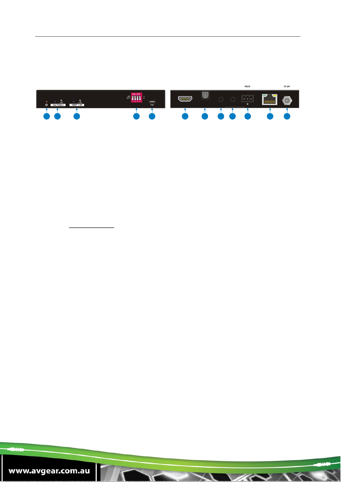
3. Product Appearance of the AVG-HD350A
Transmitter
①Power LED: The LED illuminates red when power is applied.
②Test Pattern: Press the button with paper clip or other sharp tool to enable the
test pattern, and the left LED illuminates blue, the product generates an image of
1080P/60Hz color bar to output; Press this button again, the left LED blinks blue
at an interval of 500ms, the product generates an image of 4K/60Hz 4:4:4 color
bar to output. Press and hold this button for three seconds again can exit the Test
Pattern mode.
③1080P →4K: Press the button with paper clip or other sharp tool to enable 1080P
to 4K up-scaling, and then the left LED illuminates blue. Press it again to exit.
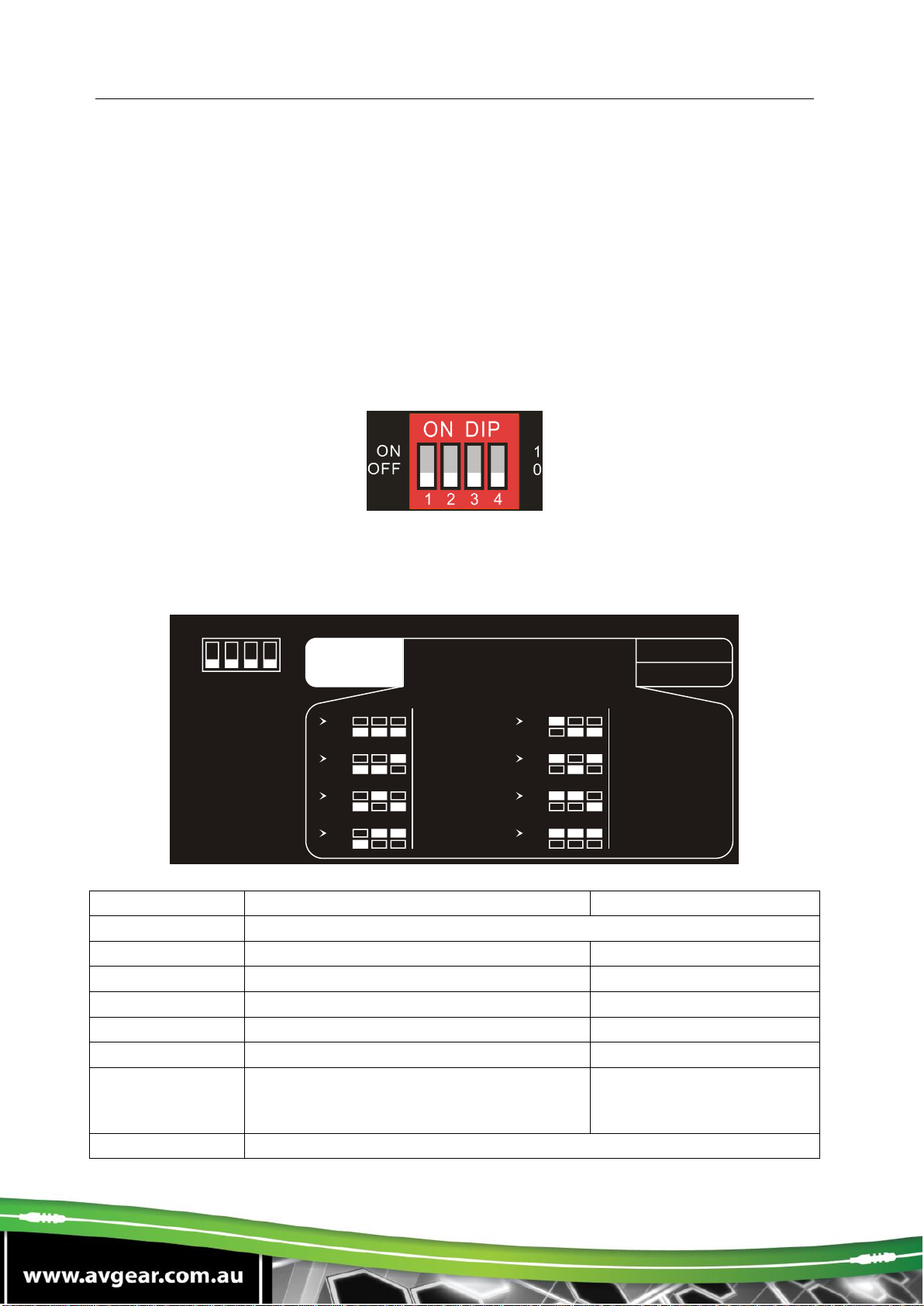
④EDID: 4-pin DIP switch for EDID setting and HDCP mode selection. Please refer
to the EDID Management for more details.
⑤FW: Micro-USB port for firmware upgrade and user-defined EDID upload.
⑥HDMI In: Type-A female HDMI input port to connect a HDMI source.
⑦ARC Audio Out: Toslink connector to connect speaker or amplifier for ARC audio
output.
⑧IR In: 3.5mm jack to connect the IR receiver for IR pass-through.
⑨IR Out: 3.5mm jack to connect the IR emitter for IR pass-through.
⑩RS232: 3-pin terminal block to connect the RS232 control device (e.g. PC) or a
third-party device to be controlled.
⑪HDBT Out: RJ45 port to connect the HDBT input port of receiver by CATx
Ethernet cable. The LINK LED illuminates orange when there is a valid HDBaseT
link between the transmitter and the receiver. The HDCP LED illuminates green
when the video contains HDCP content.
⑫DC 24V: DC connector for the power adapter connection.
Tx Rx
LINKHDCP
123 4 5678910 11 12
HDBTOut
HDMI In
IROut
IRIn
ARC Audio Out

AVG-HD350A
Receiver
①Power LED: The LED illuminates red when power is applied.
②ARC Mode: Press the button with paper clip or other sharp tool to enable the
ARC mode, and then the left LED illuminates blue. Press it again to exit the ARC
mode and the LED is off.
③ARC Audio In: Toslink connector to connect ARC audio source device (e.g.TV).
④FW: Micro-USB port for firmware upgrade.
⑤HDMI Out: Type-A female HDMI output port to connect HDMI display (e.g.TV).
⑥Audio Breakout: If the ARC mode is OFF, the Toslink connector is connected to
speaker or amplifier for HDMI source audio de-embedding. Note that if the ARC
mode is ON, this port has no audio output.
⑦IR In: 3.5mm jack to connect the IR receiver for IR pass-through.
⑧IR Out: 3.5mm jack to connect the IR emitter for IR pass-through.
⑨RS232: 3-pin terminal block to connect the RS232 control device (e.g. PC) or a
third-party device to be controlled.
⑩HDBT In: RJ45 port to connect the HDBT output port of transmitter by CATx
Ethernet cable. The LINK LED illuminates orange when there is a valid HDBaseT
link between the transmitter and the receiver. The HDCP LED illuminates green
when the video contains HDCP content.
⑪DC 24V: DC connector for the power adapter connection.
Note: Pictures shown in this manual are only for reference.
12345678911
10

AVG-HD350A
4. DIP Switch Operation
EDID Management
The Extended Display Identification Data (EDID) is used by the source device to
match its video resolution with the connected display. By default, the source device
obtains its EDID from the first connected display. Meanwhile, since the displays with
different capabilities are connected to the extender, the DIP switch on the front panel
of transmitter can be used to set the EDID to a fixed value to ensure the compatibility
in video resolution.
The switch represents “0” when in the lower (OFF) position, and it represents “1” while
putting the switch in the upper (ON) position.
Switches 1~3 are used for EDID setting. The DIP switch status and its corresponding
setting are shown on the back of the product.
Switch Status
Video Resolution
Audio Format
000
Pass Through
001
1080P
2CH
010
3840x2160@30Hz
2CH
011
3840x2160@30Hz
Multi-CH
100
3840x2160@60Hz
2CH
101
3840x2160@60Hz
Multi-CH
110
3840x2160@60Hz HDR
Multi-CH (Supports PCM
2CH, PCM5.1, Dolby
Digital 5.1,DTS 2CH)
111
User-defined EDID (Upload the EDID by Micro-USB port)
1 2 3
EDID Setting
Default
1 2 3 4
ON
OFF 1
0ON
OFF
4
HDCPActive
HDCP Passive
Pass Through
1080p 2CH
4K/30Hz Multi-CH
ON
OFF
1 2 3
ON
OFF
1 2 3
ON
OFF
1 2 3
ON
OFF
1 2 3
4K/30Hz 2CH
ON
OFF
1 2 3
ON
OFF
1 2 3
ON
OFF
1 2 3
4K/60Hz 2CH
4K/60Hz Multi-CH
4K/60Hz HDR Multi-CH
ON
OFF
1 2 3 User Defined

AVG-HD350A
Note:
▪2CH: Supports LPCM 2CH.
▪Multi-CH: Supports LPCM 8CH, Dolby TrueHD, DTS-HD , Dolby Digital5.1, DTS
5.1, Dolby Digital Plus.
⚫User-defined EDID Setting
Except directly invoking the built-in EDID, the specific EDID can be customised by
following the below operation process.
1) Rename the user-defined EDID according the following format.
EC_xx_xxxxx_xxxx_xxx.bin
⚫EC: Fixed value
⚫xx: EDID ID. It is “15”.
⚫xxxxx: Video resolution.
⚫xxxx: Refresh rate.
⚫xxx: Audio format.
Example: EC_15_3840x2160_60Hz_ Dolby.bin
2) Connect the FW port of transmitter to the PC with USB cable, and then power on
the transmitter, the PC will automatically detect a virtual disk named of
“BOOTDISK”.
3) Double-click to open the disk, a file named of “READY.TXT” will be showed.
4) Copy the user-defined EDID (such as EC_15_3840x2160_60Hz_Dolby.bin) to the
“BOOTDISK” disk.
5) Reopen the disk to check the filename “READY.TXT” whether automatically
becomes “SUCCESS.TXT”, if yes, the user-defined EDID was imported into the
transmitter and saved as its corresponding EDID ID successfully.
6) Remove the USB cable, and then reboot the transmitter.
7) Now the new EDID can be invoked by setting the DIP switch status to “111”.

AVG-HD350A
HDCP Mode
Put the switch 4 on the “ON” position to select HDCP Active mode, or on the “OFF”
position for HDCP Passive mode.
Switch Status
Mode
HDCP
OFF (0)
Passive
(Default)
Automatically follows the HDCP version of source
device.
ON (1)
Active
⚫If the input video has HDCP content, the HDCP
version of HDMI output is HDCP 1.4 for broader
video solution.
⚫If the input video has no HDCP content, the HDMI
output has no HDCP too.
5. ARC Mode
The front panel of receiver provides a button to enable or disable ARC mode, as below
figure shows:
Press the button with paper clip or other sharp tool to enable the ARC mode, and then
the left LED illuminates blue. Press it again to exit the ARC mode and the LED is off.
ARC Mode
Display (e.g.TV)
Audio Transmission Path
ON
ARC is supported
The TV audio is transmitted from the TV back to the
receiver via HDMI cable, and then it will be output by
the ARC Audio Out port of transmitter.
ARC is not
supported
Connect the TV to the ARC Audio In port of
receiver with an audio cable. The TV audio is
transmitted from the TV back to the receiver via the
audio cable, and then it will be output by the ARC
Audio Out port of transmitter.
Note that if the ARC mode is ON, the Audio
Breakout port of receiver has no audio output.
OFF
/
The TV audio can’t be back to the ARC Audio Out
port of transmitter. The Audio Breakout port of
receiver is connected to speaker or amplifier for
HDMI source audio de-embedding.

AVG-HD350A
6. System Connection
The following diagram illustrates the typical input and output connection of the
extender:
1 2 3 4
Tx Rx
LINKHDCP
Tx Rx
LINKHDCP
Speaker Laptop Remote HDTV
Speaker
HDMI:
HDBaseT:
Audio:
IR:
RS232:
ARC
ARC
Tx Rx
ARC
IR
Receiver
PoC
4K 40m 1080P 70m,
IR
Emitter

AVG-HD350A
7. Specifications
Transmitter
Receiver
Video
Input
(1) HDMI
(1) HDBT
Input Connector
(1) Type-A female HDMI
(1) RJ45
Input Resolution
Up to 4Kx2K@60Hz 4:4:4
8bit HDR10
Up to 4Kx2K@60Hz 4:2:0
Output
(1) HDBT Out
(1) HDMI
Output Connector
(1) RJ45
(1) Type-A female HDMI
Output Resolution
Up to 4Kx2K@60Hz 4:2:0
Up to 4Kx2K@60Hz 4:4:4 8bit
HDR10
Audio
Input
-
(1) ARC Audio In
Input Connector
-
(1) Toslink Connector
Output
(1) ARC Audio Out
(1) Audio Breakout
Output Connector
(1) Toslink connector
Audio Format
Supports PCM, Dolby Digital, Dolby True-HD, DTS and DTS-
HD.
Frequency
Response
20Hz –20KHz, ±3dB
Max Output Level
2.0Vrms ± 0.5dB. 2V = 16dB headroom above -10dBV
(316mV) nominal consumer line level signal
THD+N
< 0.05% (-80dB), 20Hz –20KHz bandwidth, 1KHz sine at
0dBFS level (or max level)
SNR
> 85dB, 20Hz-20 kHz bandwidth
Crosstalk Isolation
> 70dB, 10KHz sine at 0dBFS level (or max level before
clipping)
L-R Level
Deviation
< 0.3dB, 1KHz sine at 0dBFS level (or max level before
clipping)
Frequency
Response
Deviation
< ± 0.5dB 20Hz - 20KHz
Output Load
Capability
1KΩ and higher (Supports 10x paralleled 10KΩ loads)
Stereo Channel
Separation
>70dB@1KHz

AVG-HD350A
Control
Control Part
(1) Test Pattern button,
(1)1080P →4K button,
(1) EDID 4-pin DIP switch,
(1) FW, (1) IR In, (1) IR Out,
(1) RS232
(1) ARC Mode button, (1) FW,
(1) IR In, (1) IR Out, (1) RS232
Control Connector
(1) Micro-USB port,
(2) 3.5mm jacks,
(1) 3-pin terminal block
(1) Micro-USB port,
(2) 3.5mm jacks,
(1) 3-pin terminal block
General
Bandwidth
18Gbps
HDMI Standard
2.0
HDCP Version
2.2, 1.4 compliant
CEC
Pass-through
Bidirectional PoC
Supported
HDMI 2.0 Cable
Length
4K@60Hz 4:4:4 ≤ 5m, 4K@60Hz 4:2:0 ≤ 15m, 1080P ≤ 20m
Transmission
Standard
HDBaseT
Transmission
Distance
1080P@60Hz ≤ 229 feet (70 meters),
4K@60Hz ≤ 131 feet (40 meters)
Operation
Temperature
-5~ +55℃
Storage
Temperature
-25 ~ +70℃
Relative Humility
10%-90%
Power Supply
Input:100V~240V AC; Output:24V DC 1.25A
Power
Consumption
12W (Max)
Dimension
(W*H*D)
TX/RX: 140mm x 19.5mm x 84mm
Net Weight
TX:275g, RX:290g
Table of contents
Other AVGear Extender manuals

AVGear
AVGear AVG-HD100 User manual

AVGear
AVGear AVG-HD402PR User manual

AVGear
AVGear AVG-HD400DSC User manual

AVGear
AVGear AVG-DAX-100 User manual

AVGear
AVGear AVG-HD300 User manual

AVGear
AVGear AVG-HD600 User manual

AVGear
AVGear AVG-USB450 User manual

AVGear
AVGear AVG-HD320 User manual

AVGear
AVGear AVG-HD220 User manual

AVGear
AVGear AVG-HD200 SETAVG-HD200R User manual