Avic View-i HD User manual

User Manual ver 1.10
Please read carefully before using this product.

Table of Contents
1. Liability
2. Precautions
3. Components
4. Functions
5
Ft
5
.
F
ea
t
ures
6. Installation
7. Product Manual
8. PC Pla
y
er Manual
y
9. Product Trouble-Shooting
10. Specifications and Certifications
11. Warranty
2

1. Liability
1. This product was designed to assist you in driving safely
by recording driving information and data for
by
recording
driving
information
and
data
for
driver reference.
2. This product does not guaranteed to record information
on every accident.
- A minor force will not trigger the G-Force sensor to activate
EtR diThfth t thM lR d
E
ven
t
R
ecor
di
ng.
Th
ere
f
ore
th
e user mus
t
use
th
e
M
anua
l
R
ecor
d
Button located on the device itself.
3. This product is not liable for any data loss caused by
physical damage to the product or it accessories.
4. The manufacturer has no liability for any injury or damage
to property associated with the use of this product
5. The manufacturer limits any and all liability to the exclusive remedies
of product repair or replacement at the manufacturer’s discretion,
to the fullest extent permitted by the law
3
to
the
fullest
extent
permitted
by
the
law

2. Precautions (Device) Do not spray automobile cleaning products
directly to product
Product will be damaged if directly exposed to
cleaning products
Do not open/fix/alter this device
Any customer alterations will void the
warranty
Do not operate product while driving
Only operate in safe environments
Only install this product within the recommended
installation area
It could result in poor GPS reception
If d i h i ll d d d i f l
Do not use any accessories other then
those included with the recorder
The use of any additional accessories will
void the product warranty
Only use manufacturer’s power connecting
cable in direct connection to car battery
The Use of any other power cable will void the
d
If
pro
d
uct
i
s p
h
ys
i
ca
ll
y
d
amage
d
d
ur
i
ng a
f
ata
l
accidents, the recorded data may get damaged
and not be able to recover them
During sudden lighting changes, such as entering
a dark runnel, alley, or turning toward direct
sunlight on a very bright day, video recording may
be compromised and video may be at poor quality
pro
d
uct warrant
y
[Caution] Manufacturer is not liable for any problem
occurring if manufacturer’s power cable is not used
Disconnect power from device after long use of
direct power connect to car battery
Failing to do so may result in battery discharge
Rllbtfthlildi
Check the product frequently to ensure that the
camera angle is properly adjusted
After violent force is appliedto the vehicle or product,
the camera angle may be altered resulting in poor
picture quality
R
emove a
ll
su
b
s
t
ance
f
rom
th
e
l
ens,
i
nc
l
u
di
ng
the plastic film, that may affect the quality of
the recording Any obstruction may degrade
recording quality.
Do not expose this product to extreme
temperatures (high or low)
This product will be damaged if it is exposed
outside recommended working temperature
4
outside
recommended
working
temperature

Only use MicroSD memory card from the manufacturer
Product may not function correctly if un-tested MicroSD memory cards is used
Do not open/fix/modify MicroSD memory card
2. Precautions (Micro SD Card)
Do
not
open/fix/modify
MicroSD
memory
card
Product could be damaged and warranty does not cover such damage.
MicroSD memory card need to be replaced with a new product after 6month use or more Product might
malfunction if MicroSD card’s writing speed decreases.
Check MicroSD memory card’s data regularly to check its operation
[NOTE] Format SD memory card at least once a week for optimal performance
Backup from MicroSD memory card to HDD or CD/DVD if any data needs to be preserved
Data might get lost due to memory corruption in SD memory card.
Causion : Important data have to backup before format.
The format will delete all data.
HOW TO FORMAT SD CARD
1. Connect MicroSD Card to user PC
1.
Connect
MicroSD
Card
to
user
PC
2. Select [Start] -> [My Computer]
3. Select SD card driver and right click and select “Format”
4. Select “FAT32” If “FAT” format is to be selected, device will not
function normally
5. Click “Start” button
6. If you want to format the MicroSD card at device, please reference
page 13.
Do not remove SD memor
y
card durin
g
p
roduct o
p
eration while
5
ygpp
power is on
Product or SD memory card could be damaged.
Manufacturer is not liable for MicroSD card’s recorded contents outside its limited product life

Please contact your sales vendor if your are missing any components or components
are at fault
3. Product Package
B
A
S
I
C
Manual
Device MicroSD Card + Adopter
(Include PC Player) Cigar jack
Power Cable User Manual
P
A
C
K
A
G
Mount &
Double-side Tape X2 Wire Clip IR Lighting
(Include in Certain
Model Only)
E
O
P
Rear View Camera
(Include in Certain
Model Only)
6
Video out
Cable Anti-Battery
Discharge Unit
P
T
I
O
NMicroSD Reader Battery Direct
Power Cable
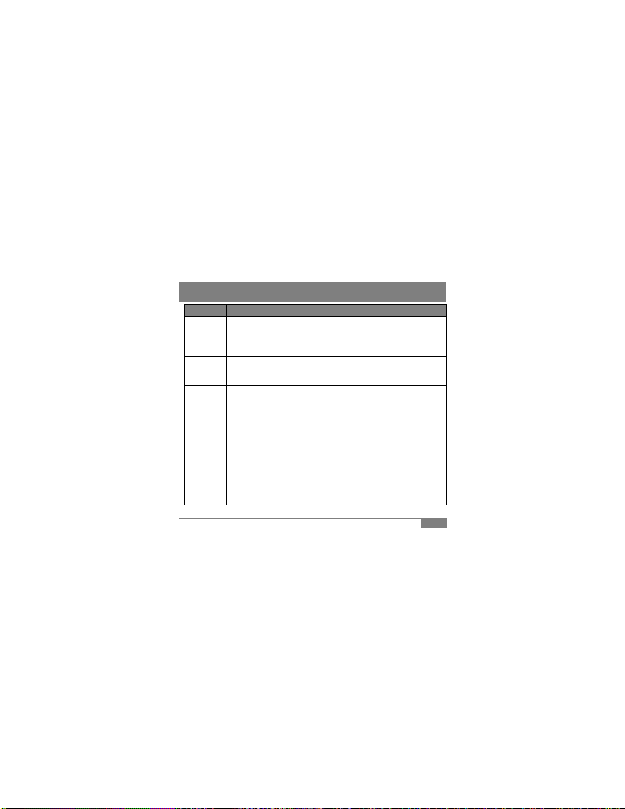
Function Description
Records ever
y
thin
g
durin
g
device
p
ower on status
4. Functions
Normal
Recording
yg g p
[NOTE] If memory exceeds its capacity, device deletes oldest file to make
room for new recordings. Therefore, if user wants to keep the old recordings, user
must backup the recordings before they are automatically deleted
Event
Recording
When device detects exceeded force in the device, device automatically saves
10 seconds before and after of the triggered event.
(Reference: 7 Product Manual)
(Reference:
7
.
Product
Manual)
Fixed
Recording
If device can’t detect any movement, such as in parking, device will automatically
set itself to fixed recording mode. Fixed Recording mode will save more
recording/hour then normal Recording Mode. When device’s camera detects
movement or G-sensor detects change of force, it will trigger event recording mode
and save them under event recording folder
Audio
Recording Supports audio recording with on/off button (Reference: 7. Product Manual)
TV-out User can check recorded files to nearest display with TV-out function
(Reference : 5. Features)
HD
Recording
HD recording at 1280x720 pixel @ 30fps Max.
7
Recording
Power Safe Supporting safe power off with internal saved power to protect deletion of last video
before power cut
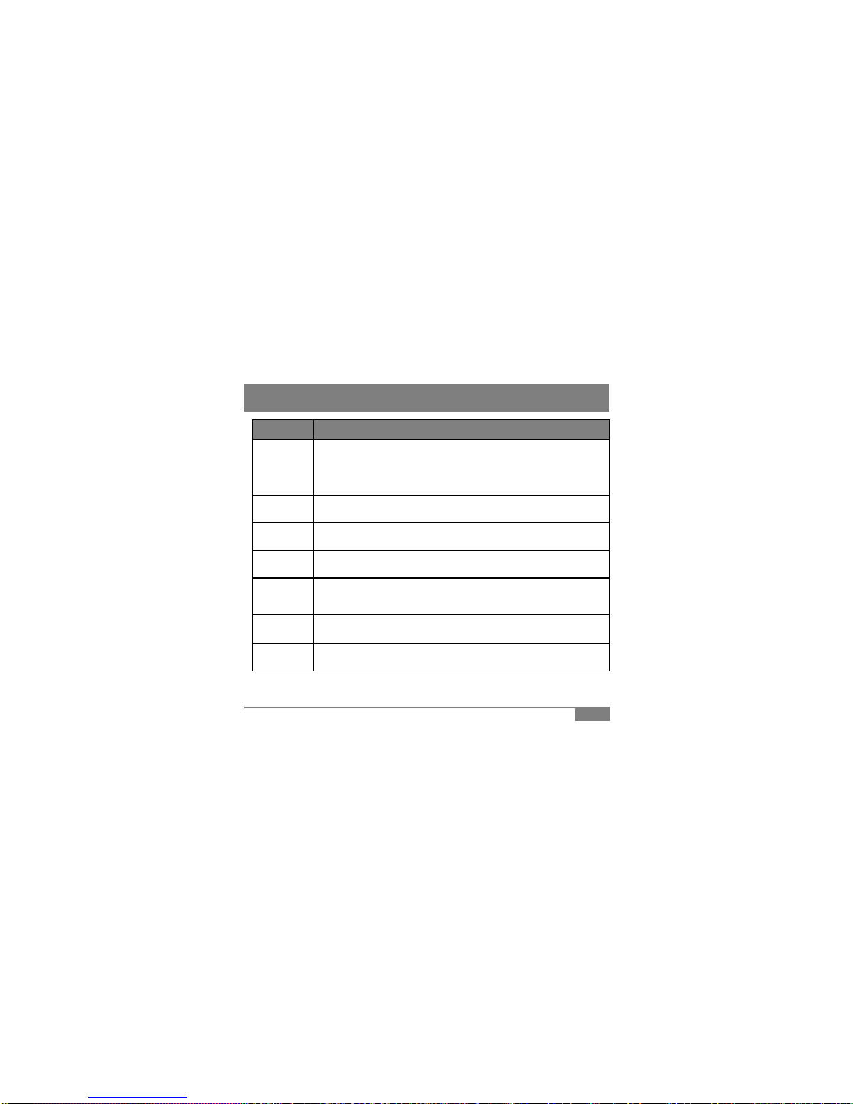
Function Description
4. Functions
Additional
Wire Camera
Additional camera can be connected via “Video-in” port to enable 2 camera
recording
(for device including 2 cameras, 2nd camera can be toggled between on-device and wire
input camera)
Status LED Blinking status LED is positioned in front of the device to alert other as a warning
Sound
Guidance Device will guide users via sound communication for easier product experience
Image
Capture User can capture image files from video recording
View driver
’
s route in Google Map embedded in PC Player
Google Map
Sync
View
driver
s
route
in
Google
Map
embedded
in
PC
Player
[NOTE] GPS needs to be connected to the satellites in order to sync
data with Google Maps
View-i PC
Player PC Player can be used to check recorded videos on MicroSD card
G
-
Sensor
View G
-
force data in PC Player to check wild driving habits or to build better
8
G
Sensor
Analysis
View
G
force
data
in
PC
Player
to
check
wild
driving
habits
or
to
build
better
driving habits thus achieving safe driving habits

# Name Description
①Power Port DC 12V~24V
5. Features
1
②Internal GPS Detect GPS info, time, and speed
③Front Camera 2M Pixel CMOS Image Sensor
④Mini USB Port 5V 400mA power input
⑤Video-in Port Connect wire camera for rear view or other angles
⑥
TV-Out Port Preview/Replay recorded files to
t di l (NTSC/PAL)
2
4
5
6
⑥
neares
t
di
sp
l
ay
(NTSC/PAL)
⑦Speaker Voice communication and guidance
⑧LED Status Red : Power / Blue : GPS Reception /
Yellow : Microphone On or Off Status
⑨Mic Button Sound recording on/off button
⑩
Power Button
Power on/off button
3
7
⑩
Power
Button
Power
on/off
button
⑪Manual Record/
Memory Format Manual Event Recording trigger or
Manually format MicroSD card
⑫Mic Records audio sounds
⑬
Internal Camera 1.3M Pixel CMOS Image Sensor
(installed in specific models only)
8
910
11 12
14
13
9
⑬
(installed
in
specific
models
only)
⑭MicroSD Slot MicroSD card input slot
⑮IR Lighting IR Lighting (included in specific models only)
15

6.1 Recommendation
Place device near rear view mirror to the driver side
where GPS and Camera does not have physical
it t
(d tdd)
6. Installation
i
n
t
errup
t
s
(
se
d
an s
t
an
d
ar
d)
[Caution] Placing device other then recommended
area may cause foul recording or GPS reception
problem. Such as heat wire or filmed windows may
cause poor GPS reception.
6.2
MicroSD Card Installation
6.2
MicroSD
Card
Installation
• Insert MicroSD Card in
same direction as the
picture. Push hard until
“click” sound is heard
• Push in the card to
release and pull in out
•Pull down
Lock switch
6.3 Installing Device to Window Mount
• Attach double
• Slide in window
mount to device until
y
ou feel a lockin
g
10
side tape to
window mount
shown in left
picture
yg
force
• Remove outside
cover of double side
tape

6. Installation
6.4 Attaching Device to the Window
1 2 3
Att h D i t
Ct ltthdi
Oi blith
IR LED Attachment (RUBY Product)
4 5
•
Att
ac
h
D
ev
i
ce
t
o
recommended area •
C
onnec
t
power p
l
ug
t
o
th
e
d
ev
i
ce
and plug in cigar jack power •
O
rgan
i
ze power ca
bl
e w
ith
wire clip
• Adjust camera angle to
best position
• Remove cover
wrapping from IR
lighting device • Attach IR device as shown in above picture
• Connect power plug
11
[Caution] Remove all substance from the lens, including the plastic film, that may affect
the quality of the recording Any obstruction may degrade recording quality

6. Installation
6.5 Installing rear view camera
Gid bl h i b it i
•
G
u
id
e ca
bl
es as s
h
own
i
n a
b
ove p
i
c
t
ure
i
n
installation
[Caution #1] Do not power on the device during cable connection.
Device will not recognize rear view camera if device is turned on and lead to malfunction.
• Plug in cable to device’s “Video-In” port
[Caution #2] Remove all substance from the lens, including the plastic film, that may affect
6.6 Device Working Confirmation
1. Confirm MicroSD card is inside the device
2. Confirm if power cable is correctly connected
3. Start
y
our en
g
ine and see red LED is turned on and
y
ou hear a sound “din
g
-don
g
”
the quality of the recording. Any obstruction may degrade recording qualit
y
12
yg y g
g
4. If all above is true, then device is working correctly and started recording after “ding-dong”
5. Blue LED will blink for few minutes and will stay lit after GPS reception is made

7. Product Manual
2
4
# Function Descri
p
tion Sound
1
2
3
5
6
p
①
Event Recording
Trigger /
Memory Format
Button
Short
Push Push this button to trigger event recording.
Record each 10secconds before and after of trigger. Ding-dong~
Long
Push
Push over 3 seconds to start memory formatting.
“Ding” sound will appear in memory format start
and “Ding-dong” will sound when it is finished Ding~/Ding~dong~
Short
Push
Push to
p
ower on the device Din
g
-don
g
~
②Power Button
Push
p
g
g
Long
Push Push over 3 seconds to power off the device Ding-dong~
③
Audio Recording
Button/
Camera mode
Change Button
Short
Push Push to turn on/off Audio recording function
(Yellow LED on/off) Ding~
Long
Push
Push this button more then 3 seconds will change
camera mode from 2CH ->1CH, vise versa.
(onl applies to 2CH prod cts)
Ding~
13
(onl
y
applies
to
2CH
prod
u
cts)
④Power LED Red LED, Power On/Off status indicator
⑤GPS LED Blue LED, Recording Status and GPS status indicator
⑥Mic LED Yellow LED, Mic On/Off status indicator

Name
Sound
LED
7.1 Buzzer/LED Scenario
7. Product Manual
Name
Sound
LED
Booting Status Ding-dong Red LED : On
Blue LED : On
Yellow LED : On
SD Card
Insert Status
If SD card is not inserted,
Device will make “Ding”
sound every second
Red LED : On
Blue LED : On
Yellow LED : On
Normal
Recording Status Silent Red LED : On
Blue LED : Operate according to GPS status
Yellow LED : Operate according to Mic status
GPS Reception
Status Silent Red LED : On
Blue LED : Blink = search / On = GPS connect
Yellow LED : operate according to Mic status
Event/Manual
Recording Status Ding-dong Red LED : On
Blue LED : Blink (Fast Blink = 0.5 sec)
Yellow LED : Blink (Fast Blink = 0.5 sec)
Mic On/Off Ding Red LED : On
Blue LED : Operate on before scenario
Yellow LED : On/off according to Mic status
14
Power Off
Status Ding-dong Red LED : Off
Blue LED : Off
Yellow LED : Off

This part of the manual explains the use of PC Player, video and utility player.
With PC Player, user may view the contents of products.
* Windows Media Player and other player may show videos but G-Sensor, GPS, MAP, Report
8. PC Player Manual
Item Description
Operating System Window XP, Windows Vista, Windows 7
CPU Pentium 4 / 2.4Ghz Processor or above
RAM More then 2GB
functions can only be used in PC Player.
8.1 System Requirement
Free HDD Space More then 200MB
Display More then 1600 x 900 pixels
8.2 Installing the Software
1. Connect the supplied PC Player to computer
2 Click [Start] and enter [My Computer] on your computer
2
.
Click
[Start]
and
enter
[My
Computer]
on
your
computer
3. Select drive that be including the PC Player and open the drive
3. Double click “setup.exe” file on the drive
4. Follow installation instructions
6. Select [Start]->[Programs]->PC Player to start the application
15

8. PC Player Manual
8.3 PC Player
Double click on “icon” to view the below screen.
1 2
3
4
5
6
7
# Name Description
①Front Video Screen Display front video recordings
②Second Video Screen Display second video recordings
③Search Search recorded files based on user preference
④Speed-o-meter /
Menu
Display driving speed
Button listing for video and menu control
16
Menu
Button
listing
for
video
and
menu
control
⑤File Information Displays file name and recording type
Displays GPS information
⑥G-Sensor Graph G-sensor data of video screen for user analysis
⑦Google Map Displays current positionof the video on Goggle map
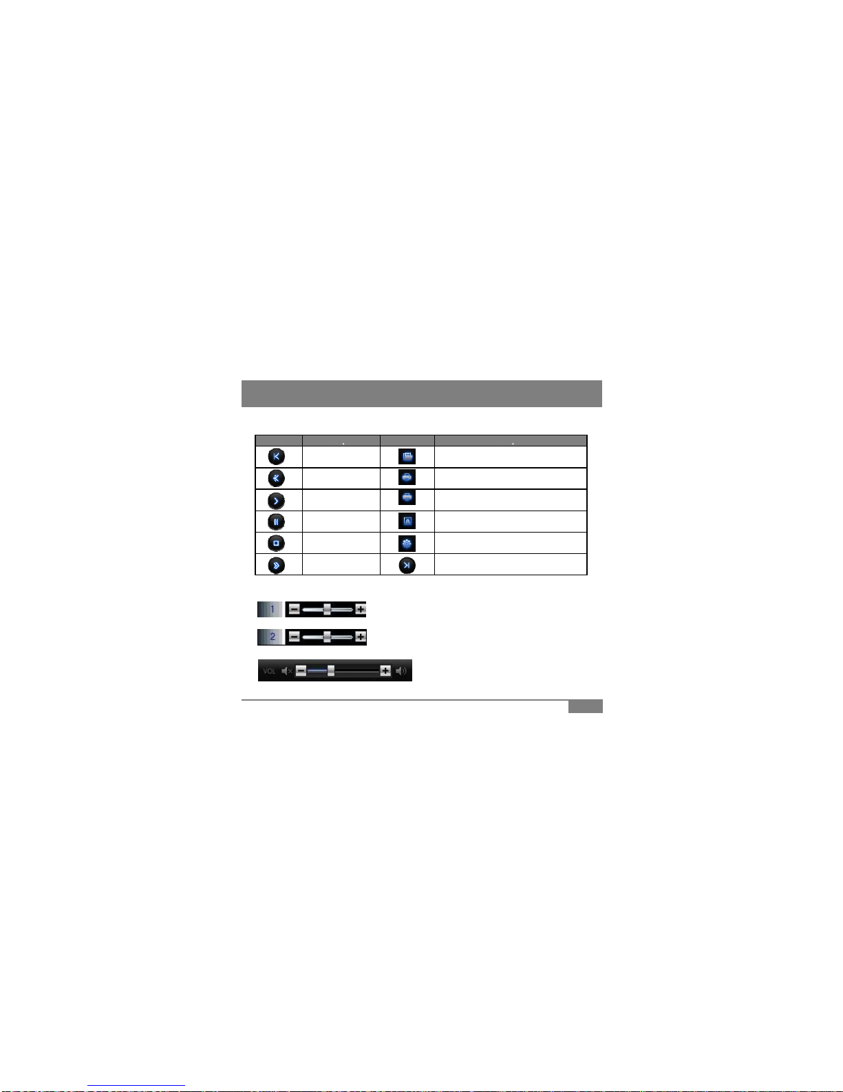
8. PC Player Manual
Button
Description
Button
Description
8.4 Buttons
Button
Description
Button
Description
Previous File Open 1 file
Rewind Print Screen
Play ECO-Drive Report
Pause Event Report
Stop Setting
Fast-forward Next File
Front video brightness adjustment
Second video brightness adjustment
8.5 Control Bar
17
Volume Control : Video volume control with mute
function
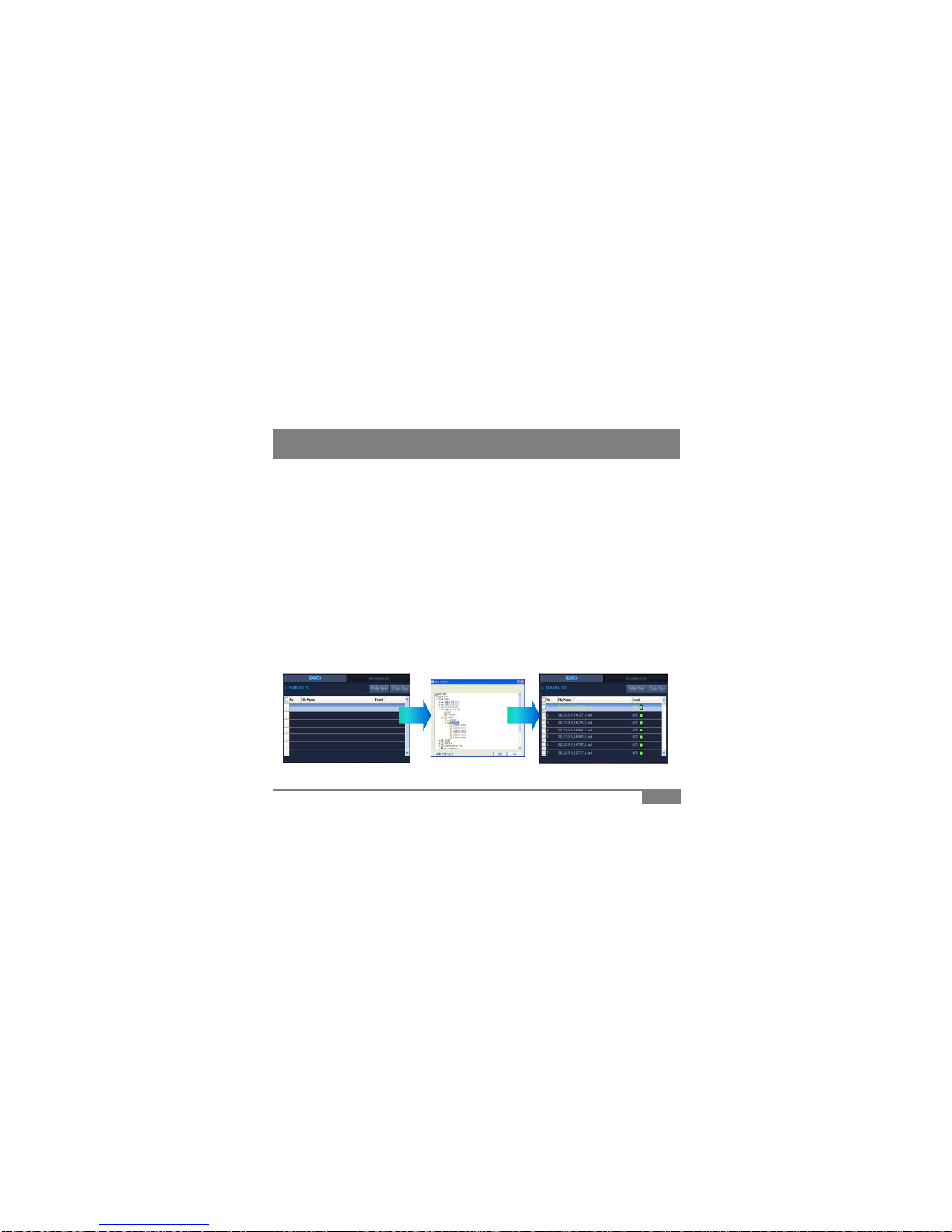
8.6 Open File / Play
8. PC Player Manual
• Recorded contents can be found inside device’s SD card.
Constant files can be found under
“
NORMAL
”
folder / folder name under date/hour
Constant
files
can
be
found
under
NORMAL
folder
/
folder
name
under
date/hour
.
• Event files are made when G sensor settings are exceeded and can be found under
“EVENT” folder.
• Move the recorded videos to user computer for best performance.
(video play navigation, search, etc)
1. Opening single file and playing
Click on the button located lower part of PC Player
Click
on
the
button
located
lower
part
of
PC
Player
.
Navigate to the folder to find the wanted play contents and double click
on the video file to play.
2. Opening a folder and playing
• Click on “Folder Open” button on the top right of Search screen.
• Navigate to the folder of user choice and select “OK” button
• When the file list appears in the Search screen, check the checkbox in the
left of the file name and click on
“
Chain Play
”
to play the videos
left
of
the
file
name
and
click
on
Chain
Play
to
play
the
videos
.
18
8. PC Player Manual
1
2
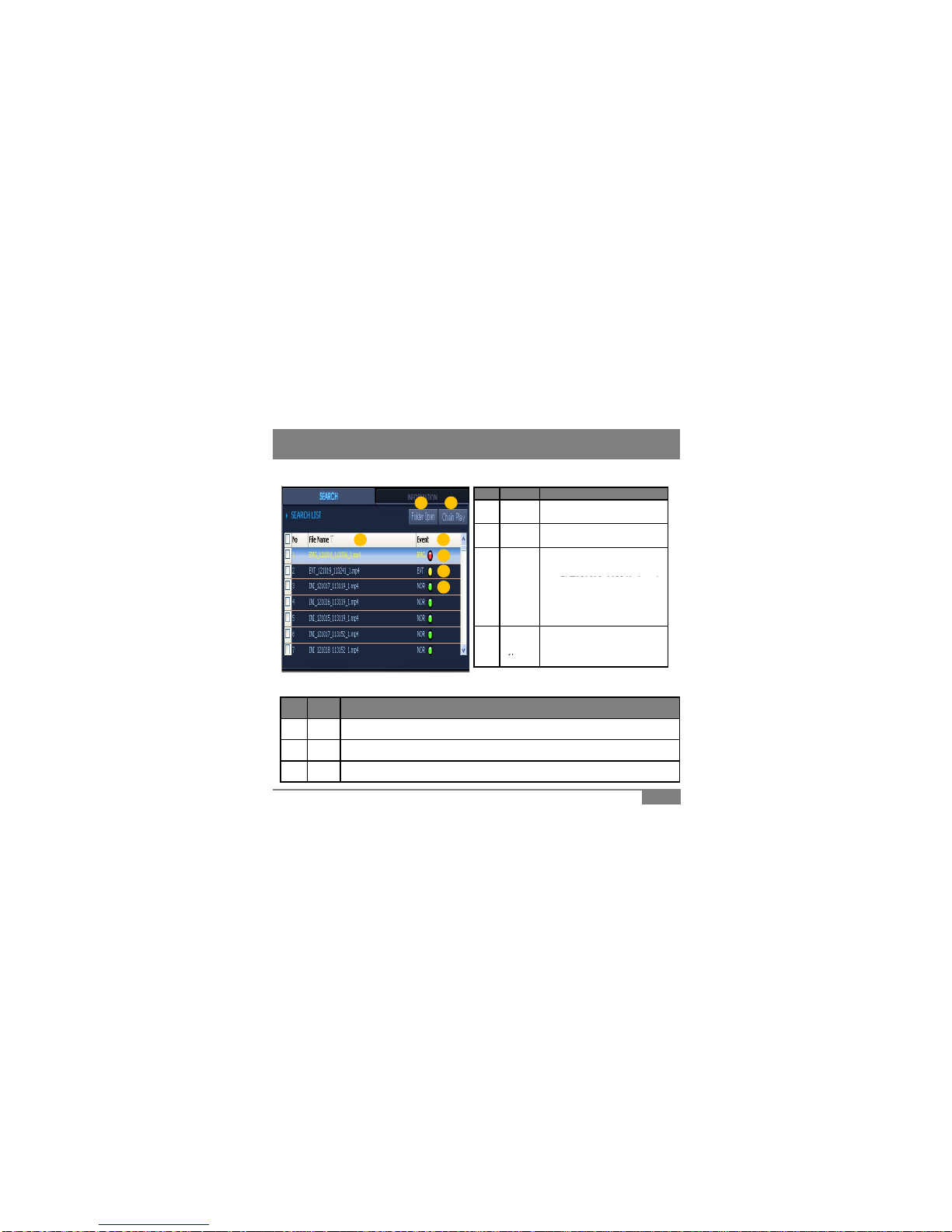
8.7 File List Screen
# Name Description
1
2
34
6
7
①Folder
Open Open a folder with recorded
videos
②Chain
Play Play button for continual playing of
checked listed files
File name consist of date/hour of
recordings.
EVT121019 113241 1 4
5③File
Name
EVT121019
_
113241
_
1
.mp
4
-> EVT or INI : Recording type
-> 121019 : 12/10/19 (date)
-> 113241 : 11:32:41 (time)
④Event
T
ype
Displays recording type.
(EVT : Event / EMG : Manual
# Name Description
⑤
NOR
Constant recording files display as
“
NOR
”
• File can be organized by clicking on the top File Name, Event titles
ype
NOR : Constant)
19
⑤
NOR
Constant
recording
files
display
as
NOR
⑥EVT G-Sensor triggered recording files display as “EVT”
⑦EMG Manual button triggered recording files display as “EMG”

8. PC Player Manual
8.8 Search - DB
1
2
3
4
1. Import play list to the Search screen (Reference : 8.6 Open File / Play)
2. Click on “Create DB” to make database
*Database must be created before searching
3. Select search option and click “Search” button
4. Searched list will appear in Search screen
5. Click on “Chain Play” to play searched file
# Name Description
①Event Type Select recording type to filter videos with selected recording type
②Speed Input speed value to filter videos above selected speed value
20
③G-Sensor Input X/Y/Z G-sensor values to filter videos above selected G-sensor value
④Time Input time value to filter videos within time section
Table of contents
Other Avic Dashcam manuals


