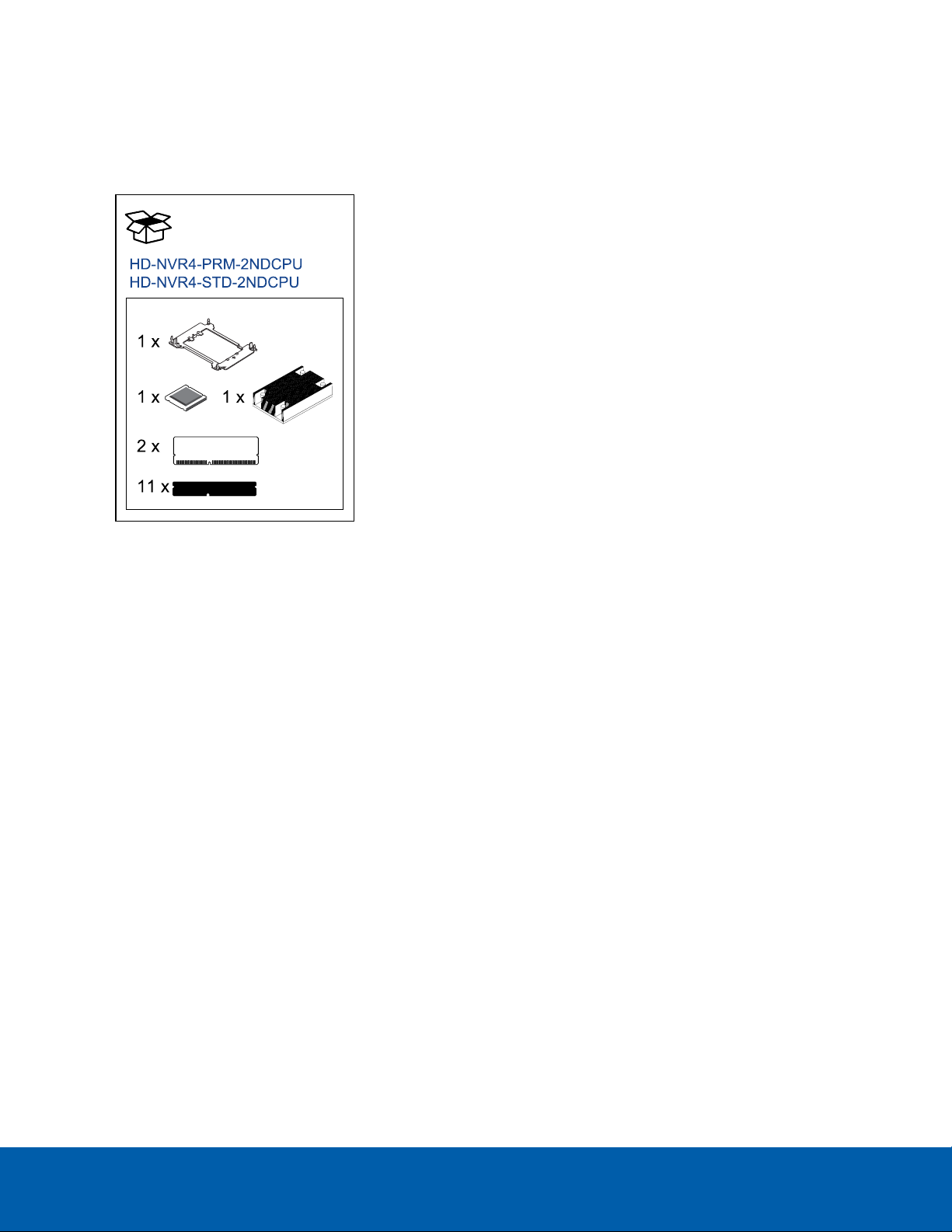
Avigilon HD-NVR4-PRM-2NDCPU Instruction Manual

Installing the NVR 2nd CPU Kits
Avigilon provides optional 2nd CPU kits for Premium and Standard network video recorders (NVR):
lNVR Premium 2nd CPUKit (HD-NVR4-PRM-2NDCPU) provides all the components needed to add
CPU redundancy to an NVR Premium.
lNVR Standard 2nd CPUKit (HD-NVR4-STD-2NDCPU) provides all the components needed to add
CPU redundancy to an NVR Standard.
NOTE: If the HDNVR is an operating part of your surveillance system, be aware that it must be shut down to
complete this procedure.
The installation procedure for both kits is very similar. Differences between the two procedures will be
noted in the steps.
Install the kit components in the following order:
Confirm Package Contents 2
Required Tools 2
1. Removing the NVR Cover 3
2. Installing the CPU 4
3. Installing the Cooling Fan (NVR4 Standard Only) 9
4. Installing RAM 10
5. Restoring the NVR 11
Installing the NVR 2nd CPU Kits 1

Confirm Package Contents
Confirm that the kit you are installing contain the following components:
l2nd CPU Kit (HD-NVR4-***-2NDCPU):
oCPU:
lHD-NVR4-PRM-2NDCPU: 1 x Intel Xeon Silver
4110 2.1 Ghz (PRM)
lHD-NVR4-STD-2NDCPU: 1 x Intel Xeon Bronze
3106 1.7 Ghz (STD)
o1 x heat sink
oRAM:
lHD-NVR4-PRM-2NDCPU: 2 x 16 GB (PRM) -
(Rank2) DDR4 RDIMM
lHD-NVR4-STD-2NDCPU: 2 x 8 GB (STD) - (Rank1)
DDR4 RDIMM
o1 x processor bracket
o11 x RAM blanks
o1 x cooling fan (HD-NVR4-STD-2NDCPU only)
Required Tools
The following tool is not included in the kit package, but is required to complete the installation:
lStar-shaped screwdriver #T30
lPhillips #2 screwdriver (for NVR Standard only, removal of butterfly riser slot)
CAUTION — It is recommended that you use a static mat or static strap to ground yourself against static
shock.
Confirm Package Contents 2

1. Removing the NVR Cover
1. Shut down the recorder.
You can skip this step if you are installing the kit on a new recorder.
a. In the Avigilon Control Center (ACC) Admin Tool, click Shut Down.
Wait for the application to display this message:
Control Center Server is Not Running
b. Shut down Windows.
2. Remove all network, power and peripheral cables from the recorder.
3. At the top of the recorder, unlock the latch release then lift and rotate the latch towards the back of
the recorder.
The cover slides back and is released from the recorder body.
1. Removing the NVR Cover 3

2. Installing the CPU
While the recorder is open, install the CPU from the kit.
1. NVR4 Premium: If you are installing the CPU on a Premium recorder, remove the mid-plane hard disk
tray.
a. Disconnect the SAS and power cables (PRM only) connected to the mid-plane hard disk tray.
b. Fold the hard drive tray handles up.
c. Use the handles to lift the tray out of the recorder.
d. Remove the black plastic cover that covers the RAM and second CPU slots. Open the RAM
ejectors that are holding the plastic cover and lift it out.
2. Installing the CPU 4

2. NVR4 Standard: If you are installing the CPU on a Standard recorder, remove the black cooling
shroud in the middle of the recorder and the butterfly riser slot that is positioned over the second
CPU slot.
a. Use a phillips #2 screwdriver to loosen the screw that is securing the butterfly riser slot.
b. Lift the butterfly riser slot out and set it aside.
c. Hold the cooling shroud by the two tabs marked in blue.
d. Lift the cooling shroud out of the recorder and set it aside.
3. Remove the CPUcap immediately over the second CPUslot. Press the 2 blue clips to remove the cap.
4. Unpack the CPU from the kit and peel off the protective layer of plastic on the bottom.
Be careful not to touch the thermal paste that is pre-applied to the bottom of the CPU.
5. Place the processor in the processor tray.
NOTE: Ensure that the pin 1 indicator on the processor tray is aligned with the pin 1 indicator on the
processor.
6. Flex the outer edges of the processor bracket and ensure that the processor is locked into the clips
on the bracket.
NOTE: Ensure that the pin 1 indicator on the bracket is aligned with the pin 1 indicator on the
processor before placing the bracket.
2. Installing the CPU 5

7. Place the heat sink on the processor and push down on the base of the heat sink until the bracket
locks onto the heat sink.
NOTE: lDo not press on the heat sink fins.
lEnsure that the 2 guide pin holes on the bracket match the guide holes on the heat
sink.
lEnsure that the pin 1 indicator on the heat sink (circled red in the image below) is
aligned with the pin 1 indicator on the bracket before placing the heat sink onto the
processor and bracket.
2. Installing the CPU 6

8. Locate the 2nd processor socket.
NVR Premium (HD-NVR4-PRM-2NDCPU) NVR Standard (HD-NVR4-STD-2NDCPU)
9. Align the pin 1 indicator on the heat sink to the system board and then place the processor and heat
sink module on the processor socket.
CAUTION — To avoid damaging the fins on the heat sink, do not press down on the heat sink fins.
NOTE: Ensure that the processor and heat sink module is held parallel to the system board to prevent
damaging the components.
2. Installing the CPU 7

10. Push the blue retention clips inward to allow the heat sink to drop into place.
NOTE: Do not force the processor into the socket. The processor should slide easily into the socket
when aligned correctly.
11. Use the star-shaped screwdriver #T30 to tighten the screws on the heat sink in the following order:
a. Partially tighten the first screw (approximately 3 turns).
b. Tighten the second screw completely.
c. Return to the first screw and tighten it completely.
NOTE: Do not over-tighten or strip the screws.
If the processor and heat sink module slips off the blue retention clips when the screws are partially
tightened, follow these steps to secure the module:
a. Completely loosen both of the heat sink screws.
b. Lower the processor and heat sink module on to the blue retention clips, following the
procedure as described in step 10 above.
c. Secure the processor and heat sink module to the system board, following the instructions as
described in step 11 above.
2. Installing the CPU 8

3. Installing the Cooling Fan (NVR4 Standard Only)
NOTE: Fan installation is only required for NVR4 Standard recorders. If you are installing the 2nd CPU into an
NVR4 Premium, proceed to step 4. Installing RAM on the next page.
While the recorder is open, install the cooling fan from the kit.
1. Locate the empty slot in the cooling fan cage and remove the fan blank.
2. Holding the release tab blue touch point on the fan, lower the cooling fan into the open slot in the
cooling fan cage.
3. Move the cables out of the way to access the cooling fan cable connector on the system board that
is near to the installed fan.
4. Route the cooling fan cable and connect it to the connector on the system board.
3. Installing the Cooling Fan (NVR4 Standard Only) 9

4. Installing RAM
After the CPU has been installed, insert the RAM included in the kit into memory sockets B1 and B2.
CAUTION — Handle each memory module only by the edges to ensure that you don't touch the middle of
the memory module or the metallic contacts.
CAUTION — To prevent damage to the memory module or memory module socket during installation, do
not bend or flex the memory module. You must insert both ends of the memory module simultaneously.
1. In the row of empty memory sockets near to the newly installed CPU, locate sockets B1 and B2.
2. Open the ejectors on the memory module sockets outward to allow the memory modules to be
inserted into the sockets.
3. Align the edge connector of the memory modules with the alignment key of the sockets and press
the memory modules into sockets until the socket levers click into place.
CAUTION — Do not apply pressure at the center of the memory module. Apply pressure to both
ends of the memory module evenly.
4. Fill the remaining empty memory sockets with the RAM blanks.
NOTE: More RAM blanks are supplied than may be necessary for the installation.
4. Installing RAM 10

5. Restoring the NVR
When all the components have been installed, restore the removed components and close the cover.
1. Reinstall the components that were immediately over the CPU.
l(Premium recorder) Reinstall the mid-plane hard disk tray. Make sure the SAS and power
cables are all reconnected.
l(Standard recorder) Restore the cooling shroud and butterfly riser slot.
2. Close and lock the recorder cover.
3. Reconnect all the cables to the recorder.
4. Power the recorder and log in to confirm the system is running properly.
©2019,Avigilon Corporation. All rights reserved. AVIGILON, the AVIGILON logo, AVIGILON CONTROL CENTER and ACC are trademarks of Avigilon Corporation. Other names
or logos mentioned herein may be the trademarks of their respective owners. The absence of the symbols ™ and ® in proximity to each trademark in this document or at all is not
a disclaimer of ownership of the related trademark. Avigilon Corporation protects its innovations with patents issued in the United States of America and other jurisdictions
worldwide (see avigilon.com/patents). Unless stated explicitly and in writing, no license is granted with respect to any copyright, industrial design, trademark, patent or other
intellectual property rights of Avigilon Corporation or its licensors.
Avigilon Corporation
avigilon.com
PDF-NVR4-2NDCPUKIT-A
Revision: 2 - EN
20190122
5. Restoring the NVR 11
This manual suits for next models
1
Table of contents
Other Avigilon Computer Hardware manuals
Popular Computer Hardware manuals by other brands

Microfluidics
Microfluidics MICROFLUIDIZER LV1 Series user manual

Infineon Technologies
Infineon Technologies XMC1100 user manual

HP
HP D7171A - NetServer - LPr installation guide

Sundance Spas
Sundance Spas SMT335E user manual

FAST ComTec
FAST ComTec MCDWIN user manual

Kontron
Kontron KBox F-420-WLU user guide