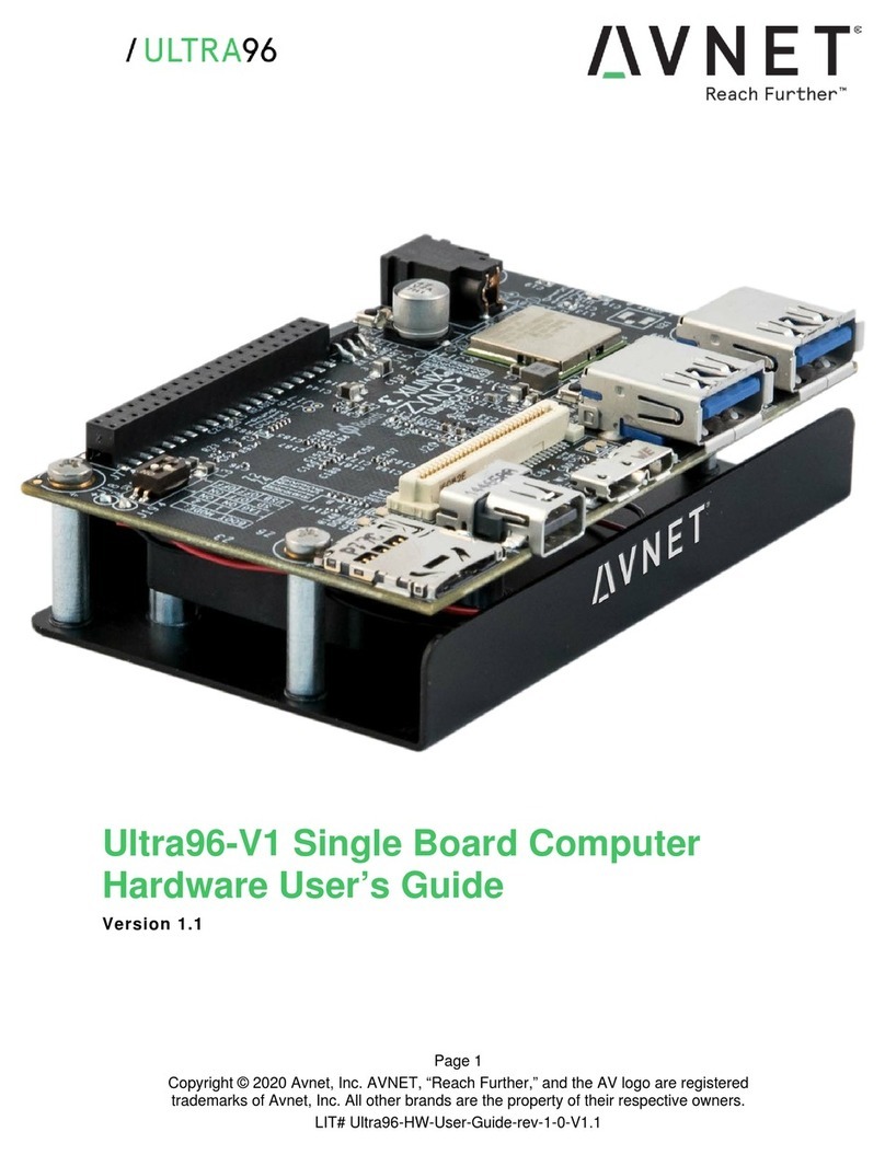
Avnet MAAXBOARD User manual

MaaXBoard
(EM-MC-SBC-IMX8M)
Linux User Manual
V1.1

MaaXBoard-Linux-Yocto-UM-V1.1
http://www.embest-tech.com 2
Copyright Statement:
The MaaXBoard single board computer (partnumber: EM-MC-SBC-IMX8M) and its related
intellectual property are owned by Avnet Manufacturing Services.
Avnet Manufacturing Services has the copyright of this document and reserves all rights. Any part
of the document should not be modified, distributed or duplicated in any approach and form without
the written permission issued by Avnet Manufacturing Services.
Disclaimer:
Avnet Manufacturing Services does not take warranty of any kind, either expressed or implied, as
to the program source code, software and documents provided along with the products, and
including, but not limited to, warranties of fitness for a particular purpose; The entire risk as to the
quality or performance of the program is with the user of products.
Regulatory Compliance:
MaaXBoard single board computer has passed the CE & FCC certification.

MaaXBoard-Linux-Yocto-UM-V1.1
http://www.embest-tech.com 3
Revision History
Rev.
Description
Author
Date
V1.0
Initial version
Sandy
20190301
V1.1
1. Add MIPI displayer, USB Device and Demo
2. Modify Wi-Fi and Camera operation
Sandy
20190705

MaaXBoard-Linux-Yocto-UM-V1.1
http://www.embest-tech.com 4
Catalog
Revision History ........................................................................................................................................... 3
Chapter 1 Introduction............................................................................................................................. 6
1.1 Package Content....................................................................................................................6
1.2 Feature List............................................................................................................................. 7
Chapter 2 Quick Start..............................................................................................................................8
2.1 Boot from SDCard..................................................................................................................8
Chapter 3 Feature Configuration & Introduction...................................................................................10
3.1 USER LED............................................................................................................................10
3.2 Button ...................................................................................................................................10
3.3 Displayer............................................................................................................................... 12
3.3.1 HDMI.............................................................................................................................12
3.3.2 MIPI-DSI Screen...........................................................................................................12
3.3.3 MIPI-LVDS Screen........................................................................................................12
3.4 Touchscreen.........................................................................................................................13
3.5 HDMIAudio ..........................................................................................................................13
3.6 UART....................................................................................................................................13
3.6.1 UART 2.......................................................................................................................... 13
3.7 Gigabit Ethernet Interface ....................................................................................................13
3.7.1 Automatic get IPAddress..............................................................................................14
3.7.2 Configure static IP.........................................................................................................14
3.8 USB 3.0 Interface.................................................................................................................14
3.8.1 USB Host....................................................................................................................... 14
3.8.2 USB Device................................................................................................................... 15
3.9 Wi-Fi .....................................................................................................................................17
3.9.1 Connect Wi-Fi................................................................................................................ 17
3.9.2 Disconnect Wi-Fi Connection........................................................................................ 17
3.9.3 Wi-Fi AP ........................................................................................................................17
3.10 Bluetooth 4.2 ........................................................................................................................18
3.11 Camera.................................................................................................................................18
3.12 GPIO (40 Pin Sense Hat) (TBD)..........................................................................................20

MaaXBoard-Linux-Yocto-UM-V1.1
http://www.embest-tech.com 5
3.13 Automatically Mount.............................................................................................................20
3.14 Desktop Environment........................................................................................................... 21
3.15 QT&GPU ..............................................................................................................................21
3.16 Play Video............................................................................................................................. 22
Chapter 4 Demo Application..................................................................................................................23
4.1 Wayland Terminal.................................................................................................................24
4.2 QtFM..................................................................................................................................... 25
4.3 Chromium............................................................................................................................. 26
4.4 WiFi_Config.......................................................................................................................... 27
4.5 Camera................................................................................................................................. 28
4.6 Video.....................................................................................................................................29
4.7 3D Example..........................................................................................................................31
4.8 QT Examples........................................................................................................................32
Chapter 5 Burn or update the system Image........................................................................................33
5.1 Burn the System Image to SD Card under Windows OS....................................................33
5.2 Burn the System Image to SD Card under Linux OS .......................................................... 34
5.3 Update System Image in eMMC..........................................................................................34
Chapter 6 Appendix...............................................................................................................................35
6.1 Hardware.............................................................................................................................. 35
Chapter 7 Technical Support and Warranty.......................................................................................... 36
7.1 Technical Support.................................................................................................................36
7.2 Warranty Conditions............................................................................................................. 36
Chapter 8 Contact Information.............................................................................................................. 38

MaaXBoard-Linux-Yocto-UM-V1.1
http://www.embest-tech.com 6
Chapter 1 Introduction
1.1 Package Content
The content of software release package is subject to the actual release sources. For the file structure
and instructions, refer to the following table:
Release Folder tree
├─01Doc
│ ├─RN
│ │ MaaXBoard-ReleaseNote-Vxx.pdf
│ └─UM
│ MaaXBoard-UserManual-Vxx.pdf
│ MaaXBoard-DevelopmentGuide-Vxx.pdf
└─02Linux
├─01LinuxSourceCode
│ linux_4.14.78_ xxx.tar.gz
│ u-boot_2018.03._xxx.tar.gz
├─02LinuxShipmentImage
│ MaaXBoard-LinuxShipmentImage-Yocto-Vxxx.img
└─03LinuxTools
gcc-linaro-7.3.1-2018.05-x86_64_aarch64-linux-gnu.tar.xz
01Doc
Description
MaaXBoard-ReleaseNote-Vxx.pdf
Release Note
MaaXBoard-UserManual-Vxx.pdf
User Manual
MaaXBoard-DevelopmentGuide-Vxx.pdf
Development Guide
01LinuxSourceCode
Description
linux_4.14.78_xxx.gz
Linux kernel source code: 4.14.78 version
u-boot_2018.03._xxx.tar.gz
u-boot source code: 2018.03
02LinuxShipmentImage
Description
MaaXBoard-LinuxShipmentImage-Yocto-Vxxx.img
Yocto image with firmwares, SD Card Image
03LinuxTools
Description
gcc-linaro-7.3.1-2018.05-x86_64_aarch64-linux-gnu.tar.xz
Gcc compiler for u-boot, kernel and
applications
xxx
Other tools

MaaXBoard-Linux-Yocto-UM-V1.1
http://www.embest-tech.com 7
1.2 Feature List
U-Boot version: 2018.03
Kernel version: 4.14.78
Evaluation image Yocto sumo 2.5
Qt 5.1.1 Library or later
Desktop
Development based on NXP i.MX 8M
Micro SD boot
HDMI display
HDMI audio output
1 Gigabit Ethernet (RJ45)
2 USB 3.0 can work in Host & Device mode
3 UART (TTL) include debug port
External interfaces(I2C, UART,SPI ,SAI and GPIO)
WIFI & BLE 4.2
MIPI-LVDS Display
MIPI-DSI Display
MIPI camera
Dual Display (TBD)

MaaXBoard-Linux-Yocto-UM-V1.1
http://www.embest-tech.com 8
Chapter 2 Quick Start
The default version of MaaXBoard support boot up from SD Card only. To burn the image to SD Card,
refer to Chapter 4.For the hardware connection and accessories details, please check the QSG.
2.1 Boot from SDCard
Install the Serial Communication software (e.g. PUTTY), select the corresponding port number,
baudrate as 115200, data bits as 8, stop bits as 1, parity as none.
Connect the debug interface to PC with USB to TTL converter. Pin 6, 8 and 10 of J10 to the GND,
RXD and TXD pin of the USB to TTL converter.
Insert the SD card (with pre-burned image) into the card slot J19.
Powered the board with a 5V, 2A, Type-C interface power (to J4).
When the system boot up, the serial terminal will print the following information:
Enter username as “root”to login.

MaaXBoard-Linux-Yocto-UM-V1.1
http://www.embest-tech.com 9
The first time to start the system and login from serial terminal, the system will install the demo application
automatically. When installation finished, system will notify the below info and reboot automatically.
After the reboot, screen will show the demo application.

MaaXBoard-Linux-Yocto-UM-V1.1
http://www.embest-tech.com 10
Chapter 3 Feature Configuration & Introduction
First of all, please refer to the previous chapter and boot up the system. Then configure or use the
functions according to the following guidance.
3.1 USER LED
User can control the 2 single color LED indicators, LED0 and LED1 (corresponding to usr_led and
sys_led) on MaaXBoard Board. Execute the following instructions in serial terminal to control them.
Light out LED:
root@imx8mqevk:~# echo 0 > /sys/class/leds/usr_led/brightness
root@imx8mqevk:~# echo 0 > /sys/class/leds/sys_led/brightness
Light up LED:
root@imx8mqevk:~# echo 1 > /sys/class/leds/usr_led/brightness
root@imx8mqevk:~# echo 1 > /sys/class/leds/sys_led/brightness
3.2 Button
MaaXBoard support 3 button: S2, S3 and S4. S2 is “PWR” button, S3 is “BACK” button, S4 is “HOME”
button.
1. Test BACK and HOME button with following instructions:
Enter evtest command, then choose the event id for gpio_keys
root@imx8mqevk:~# evtest
No device specified, trying to scan all of /dev/input/event*
Available devices:
/dev/input/event0: 30370000.snvs:snvs-powerkey
/dev/input/event1: UVC Camera (046d:0825)
/dev/input/event2: Logitech USB Optical Mouse
/dev/input/event3: SIGMACH1P USB Keykoard
/dev/input/event4: SIGMACH1P USB Keykoard
/dev/input/event5: gpio_keys
/dev/input/event6: bd718xx-pwrkey
Select the device event number [0-6]: 5
Input driver version is 1.0.1
Input device ID: bus 0x19 vendor 0x1 product 0x1 version 0x100
Input device name: "gpio_keys"
Supported events:
Event type 0 (EV_SYN)

MaaXBoard-Linux-Yocto-UM-V1.1
http://www.embest-tech.com 11
Event type 1 (EV_KEY)
Event code 102 (KEY_HOME)
Event code 412 (KEY_PREVIOUS)
Properties:
Testing ... (interrupt to exit)
Event: time 1548661524.359278, type 1 (EV_KEY), code 412 (KEY_PREVIOUS), value 1
Event: time 1548661524.359278, -------------- SYN_REPORT ------------
Event: time 1548661524.631199, type 1 (EV_KEY), code 412 (KEY_PREVIOUS), value 0
Event: time 1548661524.631199, -------------- SYN_REPORT ------------
Event: time 1548661525.683262, type 1 (EV_KEY), code 102 (KEY_HOME), value 1
Event: time 1548661525.683262, -------------- SYN_REPORT ------------
Event: time 1548661525.935198, type 1 (EV_KEY), code 102 (KEY_HOME), value 0
Event: time 1548661525.935198, -------------- SYN_REPORT ------------
2. Press PWR button for more than 8s, system will enter suspend mode, press PWR again for 1s, the
system will reboot. PWR button also support short press detective, you can test it with following
instructions:
root@imx8mqevk:~# evtest /dev/input/event0
Input driver version is 1.0.1
Input device ID: bus 0x19 vendor 0x0 product 0x0 version 0x0
Input device name: "30370000.snvs:snvs-powerkey"
Supported events:
Event type 0 (EV_SYN)
Event type 1 (EV_KEY)
Event code 116 (KEY_POWER)
Properties:
Testing ... (interrupt to exit)
Event: time 1551666457.807550, type 1 (EV_KEY), code 116 (KEY_POWER), value 1
Event: time 1551666457.807550, -------------- SYN_REPORT ------------
Event: time 1551666458.000081, type 1 (EV_KEY), code 116 (KEY_POWER), value 0
Event: time 1551666458.000081, -------------- SYN_REPORT ------------
Note: Press “CTRL+C” to exit the test.

MaaXBoard-Linux-Yocto-UM-V1.1
http://www.embest-tech.com 12
3.3 Displayer
MaaXBoard supports 3 kinds of displayer: HDMI, MIPI-LVDS and MIPI-DSI screen. Users can connect
the screen to MaaXBoard before boot up the system according to the following table. When the system
boot up, the screen will print the related startup message and login UI. Users can connect keyboard to
login the MaaXBoard file system. The default displayer is HDMI screen.
Screen Type
Interface
HDMI (Default screen)
J19 ( Standard HDMI Interface)
MIPI-DSI
J16
MIPI-LVDS
J16
Display device could be chosen by modify the fdt_file value in uEnv.txt.
Modification Method:
After the system start up, use vi command to modify the uEnv.txt under path /run/media/mmcblk0p1, use
sync command to synchronize, then reboot the system to make the modification effective.
3.3.1 HDMI
HDMI is the default displayer, the fdt_file value should be:
fdt_file=em-sbc-imx8m.dtb
The max HDMI screen resolution supported is 4K.
3.3.2 MIPI-DSI Screen
Choose MIPI-DSI screen, the fdt_file value should be:
fdt_file=em-sbc-imx8m-dcss-dsi.dtb
MIPI-DSI supports backlight brightness adjustment. The backlight brightness has a range from 0 to 255,
in which 10 means highest brightness, 0 means lowest.
Execute the following instructions on the serial terminal to implement the backlight test:
root@imx8mqevk:~# echo 7 > /sys/class/backlight/backlight/brightness
3.3.3 MIPI-LVDS Screen
Choose MIPI-LVDS screen, the fdt_file value should be:
fdt_file=em-sbc-imx8m-dcss-lvds.dtb
MIPI-LVDS supports backlight brightness adjustment. The backlight brightness has a range from 0 to 10,
in which 10 means highest brightness, 0 means lowest.
Execute the following instructions on the serial terminal to implement the backlight test:
root@imx8mqevk:~# echo 5 > /sys/class/backlight/lvds_backlight/brightness

MaaXBoard-Linux-Yocto-UM-V1.1
http://www.embest-tech.com 13
3.4 Touchscreen
Connect the screen module to J16, execute the following instructions on the serial terminal to implement
the touch screen calibration program:
root@imx8mqevk:~# ts_calibrate
Following the notes on LCD, click the “+” icon for five times to complete the calibration.
3.5 HDMI Audio
Choose HDMI screen as displayer, connect HDMI displayer and theAudio devices, play the audio file:
root@imx8mqevk:~# aplay audio_sample.wav
root@imx8mqevk:~# gst-play-1.0 audio_sample.wav
Note: aplay command support audio file in wav format, gst-play command support wav, mp3 and aac
format.
3.6 UART
MaaXBoard supports 2 UART interface.
MaaXBoard (CPU)
Interface Type
UART1
UART TTL (Debug Interface)
UART2
UART TTL
3.6.1 UART 2
In the Yocto system, the node for UART2 is /dev/ttymxc1.
The system image provides a test application, uart_test, which could be used for a loop back test.
Short connect the pin 16 and 18 in J10, then enter the following instructions in serial terminal:
root@imx8mqevk:~# ./uart_test -d /dev/ttymxc1 -b 115200
/dev/ttymxc1 RECV 10 total
/dev/ttymxc1 RECV: 1234567890
The result of RECV as above, means test passed.
Note: Press “CTRL+C” to exit the test.
3.7 Gigabit Ethernet Interface
Connect the network cable to J13, enter the following instructions to set the IP address:
(The below IP address are example, replace it with your real network environment)

MaaXBoard-Linux-Yocto-UM-V1.1
http://www.embest-tech.com 14
3.7.1 Automatic get IP Address
When you connect the network cable, MaaXBoard will get the IP address automatically, you can check
the IP address with ifconfig command, and test the network with the following instruction:
root@imx8mqevk:~# ping www.baidu.com
3.7.2 Configure static IP
If you need to set a static IP, execute the following instructions:
You may need to add route info as below:
route add default gw 192.168.8.254
Set static IP address:
root@imx8mqevk:~# ifconfig eth0 192.168.8.119
Network test:
root@imx8mqevk:~# ping www.baidu.com
3.8 USB 3.0 Interface
The USB 3.0 interface HUB1 on have 2 USB Host Interface, the upper one is USB1, the lower one is
USB0. USB0 and USB1 both support USB HOST function, USB0 support USB Device function.
3.8.1 USB Host
Insert a U-disk to USB0 or USB1, serial terminal will display the disk information:
[ 541.484723] usb 2-1: new SuperSpeed USB device number 2 using xhci-hcd
[ 541.548910] usb-storage 2-1:1.0: USB Mass Storage device detected
[ 541.558886] scsi host0: usb-storage 2-1:1.0
[ 542.593679] scsi 0:0:0:0: Direct-Access Kingston DataTraveler 3.0 PQ: 0 ANSI: 6
[ 542.604306] sd 0:0:0:0: [sda] 30218842 512-byte logical blocks: (15.5 GB/14.4 GiB)
[ 542.612602] sd 0:0:0:0: [sda] Write Protect is off
[542.618045] sd 0:0:0:0: [sda] Write cache: disabled, read cache: enabled, doesn't support DPO
or FUA
[ 542.632439] sda: sda1
[ 542.636616] sd 0:0:0:0: [sda] Attached SCSI removable disk
[ 542.817343] FAT-fs (sda1): Volume was not properly unmounted. Some data may be corrupt.
Please run fsck.
Execute the following instructions on the serial terminal:
root@imx8mqevk:~# ls /dev/sd*
/dev/sda /dev/sda1
Storage nodes for U disk is /dev/sda, you can use mount command to mount the device for further use.
EM-MC-SBC-IM8M also supports other USB device such as key board and mouse.

MaaXBoard-Linux-Yocto-UM-V1.1
http://www.embest-tech.com 15
3.8.2 USB Device
USB0 support USB Device function could be used to burn the system image or use as USB Network
adapter.
3.8.2.1 BURNING MODE
Connect USB0 and PC before power on the board. The system will not boot normally, it will enter burning
mode. Then users could burn the system image to the development board using uuu tools. For the detail
information, refer to MaaXBoard EMMC burning Guide.
3.8.2.2 USB NETWORK ADAPTER
To use USB0 as USB network adapter, users should modify the value of fdt_file in uEnv.txt and reboot the
system.
fdt_file=em-sbc-imx8m-usb0-device.dtb
When choose this value, the displayer is HDMI.
Connect USB0 to PC after the system start up, open the device manager, and check if the following
device is recognized:
Please follow the steps listed below to finish USB Device test (Use Windows 7 as example).
1) Install Linux USB Ethernet driver (In release package: LinuxTools), then the device manager will list
the Network Adapter: Linux USB Ethernet/RNDIS Gadget
2) Execute the following instructions to set and view the IP address of USB OTG port
The below IP address are example, you can select any other IP, but make sure it is NOT the same
network segment as your PC’s Ethernet port.
root@imx8mqevk:~# ifconfig usb0 up
root@imx8mqevk:~# ifconfig usb0 192.168.1.115
root@imx8mqevk:~# ifconfig
The terminal window will print information as shown below
usb0 Link encap:Ethernet HWaddr 92:a9:b6:be:8b:3f
inet addr:192.168.1.115 Bcast:192.168.1.255 Mask:255.255.255.0
inet6 addr: fe80::90a9:b6ff:febe:8b3f/64 Scope:Link
UP BROADCAST RUNNING MULTICAST MTU:1500 Metric:1
RX packets:167 errors:0 dropped:0 overruns:0 frame:0
TX packets:28 errors:0 dropped:0 overruns:0 carrier:0
collisions:0 txqueuelen:1000
RX bytes:12180 (11.8 KiB) TX bytes:7075 (6.9 KiB)
3) Open Control Panel, in the search box, type adapter, and then, under Network and Sharing Center,

MaaXBoard-Linux-Yocto-UM-V1.1
http://www.embest-tech.com 16
select View network connections, you will find a new Local Area Connection as shown below
4) Right click the connection “Local Area Connection 5”, select “Properties”-> “Networking”-> “Internet
Protocol Version 4 (TCP/IPv4)”, then select Properties to open the following window. Set an IP address
that is in the same network segment as the USB OTG port, then click “OK”.
5) Execute the following instruction to verify the network connection;
root@imx8mqevk:~# ping 192.168.1.15
PING 192.168.1.15 (192.168.1.15) 56(84) bytes of data.
64 bytes from 192.168.1.15: icmp_seq=1 ttl=64 time=0.865 ms
64 bytes from 192.168.1.15: icmp_seq=2 ttl=64 time=0.464 ms
64 bytes from 192.168.1.15: icmp_seq=3 ttl=64 time=0.259 ms
The information shown above indicates the network connection is working properly.

MaaXBoard-Linux-Yocto-UM-V1.1
http://www.embest-tech.com 17
3.9 Wi-Fi
The on-board Wi-Fi module support 2.4G/5G network.
3.9.1 Connect Wi-Fi
To connect WIFI, execute the following instructions on the serial terminal:
root@imx8mqevk:~# ./wifi_sta_connect.sh Embest-WiFi 12345678
In above instruction: “Embest-WiFi” is the SSID of the WIFI, “12345678” is the password.
If the connection succeeds, it will print the following info:
udhcpc: sending discover
udhcpc: sending select for 192.168.1.141
udhcpc: lease of 192.168.1.141 obtained, lease time 86400
/etc/udhcpc.d/50default: Adding DNS 192.168.1.1
Test Wi-Fi network with ping command:
root@imx8mqevk:~# ping www.baidu.com -I wlan0
PING www.a.shifen.com (103.235.46.39) 56(84) bytes of data.
64 bytes from 103.235.46.39: icmp_seq=1 ttl=50 time=122 ms
3.9.2 Disconnect Wi-Fi Connection
To disconnect WIFI, execute the following instructions on the serial terminal:
root@imx8mqevk:~# ./wifi_stop.sh
If the operation success, it will print the following info:
Terminating DHCP
3907
Terminating hostapd
Terminating wpa_supplicant
root 3887 1 0 09:25 ? 00:00:00 wpa_supplicant -B -i wlan0 -c /etc/wpa_supplicant.conf -D nl80211
sending signal 15 to procs
wlan0 has been disconnected on STA mode and AP mode !
3.9.3 Wi-Fi AP
To open a Wi-Fi hotspot, connect the network cable to J13, execute the following instructions on the serial
terminal:
root@imx8mqevk:~# ./wifi_ap_start.sh
Configuration file: /etc/hostapd_mx8.conf
rfkill: Cannot open RFKILL control device

MaaXBoard-Linux-Yocto-UM-V1.1
http://www.embest-tech.com 18
wlan0: Could not connect to kernel driver
Using interface wlan0 with hwaddr 80:c5:f2:7f:6e:cd and ssid "wifi_testAP"
wlan0: interface state UNINITIALIZED->ENABLED
wlan0: AP-ENABLED
Now, you can connect Wi-Fi device to this hotspot, the default ssid is wifi_testAP, password is 12345678.
If you need to modify it, use vi command to modify the related parameter in /etc/hostapd_mx8.conf,
then reopen the hotspot.
Shut off the Wi-Fi connection: use ./wifi_stop.sh command
3.10 Bluetooth 4.2
Execute the following instructions in the serial terminal:
root@imx8mqevk:~# ./ bluetooth_start.sh
System will open Bluetooth module and scan the Bluetooth device.
3.11 Camera
MaaXBoard support USB Camera and MIPI-CSI Camera. System provide a Camera application, could be
used with desktop environment to preview, photograph and record video.
Connect a displayer, camera to MaaXBoard, make sure the desktop environment is start up.
To use the Camera application, execute the following instructions in the serial terminal:
root@imx8mqevk:~# ./Camera
Note: Press “CTRL+C” in serial terminal or click “X” on the screen to exit the camera application.
The Camera application will be shown on the screen:

MaaXBoard-Linux-Yocto-UM-V1.1
http://www.embest-tech.com 19
Choose uvcvideo when you use the USB camera, choose mx6s-csi when you use MIPI-CSI camera.
Click the Camera button on screen, to open Camera and preview the video.
Click Capture button to take a photo and show the thumbnail in the right side of the window. Click Video, it

MaaXBoard-Linux-Yocto-UM-V1.1
http://www.embest-tech.com 20
will record yuv video file in yuyv format, users could copy it to PC to check with YUVplayer.
Click the thumbnail to close the camera preview and show the whole image in current window.
3.12 GPIO (40 Pin Sense Hat) (TBD)
TBD
3.13 Automatically Mount
When storage device is connected with the board, Yocto system will mount the storage device to
/run/media path, for example:
root@imx8mqevk:~# ls /run/media/
mmcblk0p1 sda1
In this example, mmcblk0p1 is the first partition of SD Card, sda1 is U disk.
Other manuals for MAAXBOARD
2
This manual suits for next models
1
Table of contents
Other Avnet Single Board Computer manuals
Avnet
Avnet MaaXBoard AES-MC-SBC-IMX8M-G User manual
Avnet
Avnet MAAXBOARD User manual

Avnet
Avnet MaaXBoard AES-MC-SBC-IMX8M-G Instructions for use
Avnet
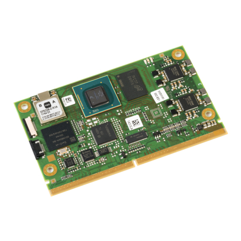
Avnet SMARC MSC SM2S-IMX8M User manual
Avnet
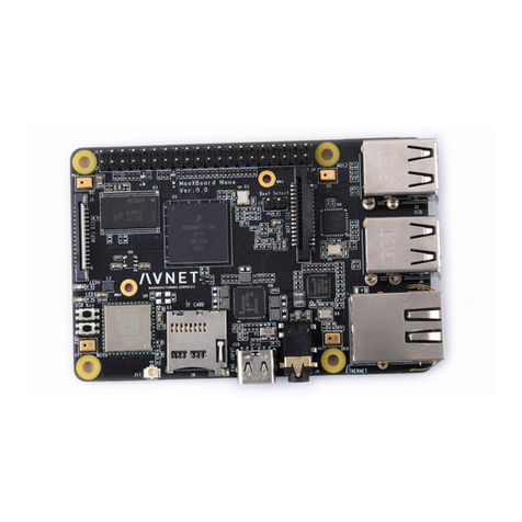
Avnet MaaXBoard Mini User manual

Avnet
Avnet MaaXBoard Mini User manual
Avnet
Avnet ZUBOARD 1CG User manual

Avnet
Avnet MaaXBoard Nano User manual

Avnet
Avnet Reach Further Ultra96-V2 User manual
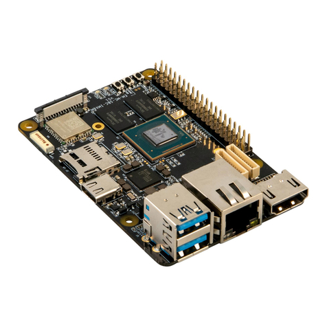
Avnet
Avnet MAAXBOARD User manual

