AVT MAGIC AE4 User manual

MAGIC AE4 DAB/DAB+
Audio Encoder
Quad DAB/DAB+ Audio Encoder
Hardware Manual

2
A publication of
AVT Audio Video Technologies GmbH
Nordostpark 91
90411 Nuernberg
Germany
Phone +49-911-5271-0
Telefax +49-911-5271-100
© AVT Audio Video Technologies GmbH
All Rights reserved. Reproduction in
whole or in parts is prohibited without the
written consent of AVT GmbH.
Subject to changes.
Release date: October 2018
Version 1.0

3
INDEX
1Introduction ....................................................................................................... 4
1.1 Conventions .................................................................................................. 4
1.2 Safety ............................................................................................................ 5
1.3 General safety requirements ........................................................................ 5
1.4 Construction.................................................................................................. 6
1.5 Functionality ................................................................................................. 7
2Putting MAGIC DABMUX Go RF into operation ................................................. 8
2.1 Mounting ...................................................................................................... 8
2.2 Connection to the mains voltage .................................................................. 8
2.3 Operational elements at the front side......................................................... 9
2.4 Alarm indication LEDs ................................................................................... 9
2.5 Wiring.......................................................................................................... 10
2.6 Proper disposal ........................................................................................... 11
3Interfaces ......................................................................................................... 12
3.1 LAN 1 and LAN 2 interfaces......................................................................... 13
3.2 TTL/Relay interface ..................................................................................... 14
3.3 Headphone interface .................................................................................. 15
3.4 Analogue Audio interface ........................................................................... 15
3.5 Digital Audio interfaces............................................................................... 16
3.6 Clock interfaces........................................................................................... 16
4Technical Data.................................................................................................. 17
5General ............................................................................................................ 21
5.1 Order numbers............................................................................................ 21
5.2 Scope of delivery......................................................................................... 21
5.3 Declaration of conformity........................................................................... 21
6Service Information.......................................................................................... 22
6.1 Software and firmware updates ................................................................. 22
6.2 Support ....................................................................................................... 22
6.3 Repairs ........................................................................................................ 22

4
1INTRODUCTION
MAGIC AE4 DAB/DAB+ Audio Encoder offers in the standard version one
DAB/DAB+ hardware encoder and can be optionally upgraded to a dual, triple
or quad DAB/DAB+ encoder. Each of the four channels are independent and can
be configured independently as a DAB or DAB+ encoder.
The audio programs can be supplied via the four digital AES/EBU stereo
interfaces. An analogue Stereo interface is also available. The unit offers a
headphone interface on the front side.
MAGIC AE4 is realized in a compact, fan less and DSP-based design and has an
integrated wide area power supply, a keypad with display and LEDs on the front
side.
1.1 Conventions
In this manual the following conventions are used as text markers:
The TIP symbol marks information which facilitates the operation of the system in
its daily use.
The Note symbol marks general notes to observe.
The Attention symbol marks very important advice that is absolutely to observe. In
case of non-observance malfunctions and even system errors are possible.

5
1.2 Safety
The unit described has been designed to the latest technical parameters and
complies with all current national and international safety requirements. It
operates on a high level of reliability because of long-term experience in de-
velopment and constant and strict quality control in our company.
This manual contains basic safety instructions that must be observed during
configuration and operation. It is essential that the user reads this manual before
the system is used and that a current version of the manual is always kept close to
the equipment.
1.3 General safety requirements
To keep the technically unavoidable residual risk to a minimum, it is absolutely
necessary to observe the following rules:
•Transport, storage and operation of the unit must be under the
permissible conditions only.
•Installation, configuration and disassembly must be carried out only by
trained personal on the basis of the respective manual.
•The unit must be operated by competent and authorised users only.
•The unit must be operated in good working order only.
•The device must be protected from water.
•The device may only be installed in indoor rooms.
•The device may only be cleaned with a dry cloth.
•Any conversions or alterations to the unit or to parts of the unit (including
software) must be carried out by trained personnel authorised by the ma-
nufacturer. Any conversions or alterations carried out by other persons
lead to a complete exemption of liability.
•Only specially qualified personnel are authorised to remove and override
safety measures, and to carry out the maintenance of the system.
•External software is used at one’s own risk. Use of external software can
affect the operation of the system.
•Use only tested and virus-free date carriers.

6
1.4 Construction
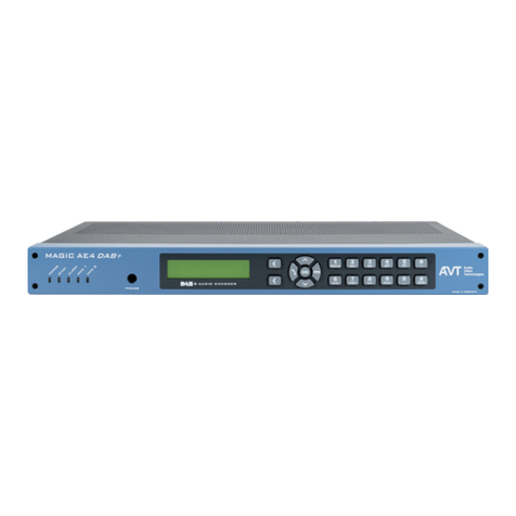
MAGIC AE4 contains a mainboard with an additional connector, a display, a keypad
and five LEDs as well as a headphone interface on the front side.
The functions of the system are implemented in a 19” x 1U housing, the dimensions
are 434mm x 44,5mm , 252mm. MAGIC AE4 can be used as a table-top device or it
can be mounted in a 19” rack. The 19” mounting brackets are included in delivery.
MAGIC AE4 Front View
MAGIC AE4 Rear View

7
1.5 Functionality
MAGIC AE4 offers in the standard version one DAB/DAB+ hardware encoder and
can be optionally upgraded with three further encoders. Each of the four channels
are independent and can be configured independently as a DAB or DAB+ encoder.
The audio programs can be supplied via the four digital AES/EBU stereo interfaces.
An analogue stereo interface is also available.
The PAD is usually fed in via the Ensemble Multiplexer, which scans the PAD via the
return path of the transmission protocol on the encoder. All PAD services
supported by the multiplexer can be used.
Alternatively, it is also possible to feed PAD services directly into the Encoder.
In addition to PAD, service information such as the Program Type (PTy) and Traffic
Announcement (TA) can also be transmitted via UECP for each program. The
triggering of a traffic announcement can be easily implemented via a TTL contact.
As transmission protocols with reconfiguration capability and PAD insertion, the
system supports the proprietary standards AVTMUX, FhG MuxEnc, AVTVDL and
ODR DabMux.
The EDI (ETI) standard also allows the system to be connected to almost any
Ensemble Multiplexer from other manufacturers. In this case, however,
reconfiguration and PAD feeding from the multiplexer is not possible, since EDI
cannot transfer control information.
Two network interfaces are available as standard. Up to three IP addresses can be
assigned to each Ethernet interface.
In addition, the system supports VLANs for all kinds of services such as audio & PAD,
SNMP, UECP and NTP, making it easy to separate the subnets for audio
transmission, data transfer and management.
For monitoring, but also for assessing the quality of the encoded audio signal, a
Monitoring Decoder is also integrated, which enables direct monitoring of the
uncoded and encoded signal.
The monitoring can be done either via the headphone interface on the front or via
the analogue and digital audio interfaces on the rear panel.
A comfortable configuration and monitoring of all four encoders is carried out via a
modern HTML5-capable web browser.
In addition, the device can be integrated into a network management system via
SNMP.
Finally, eight TTL inputs/outputs and eight relays can be freely programmed, e. g.
for alarming.

8
2PUTTING MAGIC DABMUX GO RF INTO OPERATION
2.1 Mounting
With its dimensions (W ×H ×D) of 434 mm ×44,5 mm (1 U) ×252 mm the MAGIC
AE4 system can be used either as desktop device or mounted in 19-inch racks. The
mounting brackets are included in delivery.
When mounting the unit please keep in mind that the bending radius of the
connected cables is always greater than the minimum allowed value. It must also
be ensured that the power cable is installed close to the equipment and is easily
accessible.
When the unit is installed, please make sure that there is sufficient air ventilation: it
is recommended to keep a spacing of ca. 3cm from the openings. In general, the
ambient temperature of the system should be within the range of +0°C and +45°C.
This threshold is specially to observe if the system is inserted in a rack. The system
works without ventilation.
The temperature of the system can be displayed via the System Monitor of the web
interface.
During operation humidity must range between 30% and 85%.
Incorrect ambient temperature and humidity can cause functional deficiencies.
Improper use of the unit can lead to a loss of warranty claim.
2.2 Connection to the mains voltage
MAGIC AE4 must be earthed. The earthing can be carried out via the earthing screw
on the back side of the unit.
MAGIC AE4 may only be used with the included power cable. The power cable must
not be replaced by an inadequately dimensioned power cable.
The unit has a circuit closer. After plugging in the power cable and pressing the
circuit closer, the system boots within a few seconds.

9
2.3 Operational elements at the front side
The system has an illuminated graphical display with a resolution of 160 x 32 pixels
and 21 operating buttons.
On the right side next to the display there are two softkeys whose current functions
are indicated on the display. In the middle there are two buttons for navigation
(selection upwards/downwards) and the OK button. The numerical pad supports in
addition to the numerical 0…9 also the ‘*’ and ‘#’ button. For entering text, the
numerical pad can also be used as a normal keypad.
2.4 Alarm indication LEDs
The system has five LEDs for status indication. When the device boots, all five LEDs
blink.
•POWER: green
oOFF
oON
•SYNC: yellow
oOFF (no alarm)
oBLINK (system clock missing)
•ALARM: red
oOFF (no alarm)
oON (any application alarm)
oBLINK (any hardware alarm)
•INFO 1: yellow
oOFF (no audio alarm)
oON (any audio level alarm)
oBLINK (any AES/EBU alarm)
•INFO 2: yellow
oOFF (no PAD alarm)
oON (no input from external PAD server or Local PAD Inserter fall-
back active)
oBLINK (no PAD available on encoder)

10
2.5 Wiring
The system offers four digital AES/EBU stereo Audio interfaces and one analogue
stereo Audio interface. Eight TTL inputs/outputs and eight relays can be freely
programmed, e. g. for alarming. Two network interfaces are available as standard.
The system must be earthed via the earthing screw. After plugging in the power
cable on the left side and pressing the circuit closer, the system boots within a few
seconds.
1 x Analogue Stereo Inputs
4 x AES/EBU Stereo In-/Outputs
1 x Analogue Stereo Outputs
8 x programmable TTL In-/Outputs
8 x programmable Relays
2 x LAN
Earthing
screw

11
2.6 Proper disposal
All electrical and electronic equipment must be disposed separately
from general household waste via authorised collection points or
disposal companies. Proper disposal and separate collection of old
appliances serves to prevent potential damage to the environment
and health. The device contains valuable raw materials that can be
reused. Therefore, return the appliance to an appropriate collection
point.
Detailed information on the disposal of your old appliances can be obtained from
your local authority, your waste disposal service, the specialist dealer where you
purchased the product or your sales contact.
These statements apply only to equipment installed and sold in the countries of the
European Union. Countries outside the European Union may have different
regulations for the disposal of electrical and electronic equipment.
Always recycle packaging material and electrical appliances or their components
through authorised collection points or disposal companies.

12
3INTERFACES
On the front side of the unit 5 LEDs for status indication and a headphone interface
for monitoring are available. The connectors for the interfaces are at the rear side.
MAGIC AE4 Front View
MAGIC AE4 Rear View

13
3.1 LAN 1 and LAN 2 interfaces
All services (Audio, PAD, SNMP, NTP, etc.) can be configured freely for both
network interfaces. For the LAN interface a RJ45 socket is used. The pin assignment
of the socket is shown below.
Table: LAN Interface
Pin
Signal
Electrical characteristics
1
TX+
Data out +
Socket: Western 8 pin, RJ45
Recommendation: IEEE 802.3/Ethernet
Data rate (Auto neg.): 10/100 Mbit/s
Recommended cable: CAT5 or higher
Max. cable length: 100m
2
TX-
Data out -
3
RX+
Data in +
4
not used
5
not used
6
RX-
Data in -
7
not used
8
not used

14
3.2 TTL/Relay interface
The TTL / Relay interface is realised as a 25-pin socket. It provides 8 TTL in- puts or
outputs and 8 Relay contacts. The pin assignment of the socket is shown below.
Table: TTL/Relay interface
Pin
Signal
Direction
Electrical characteristics
1
TTL 1
input/output
TTL interface:
Capacity of the TTL outputs:
Maximum voltage: 3.3V
Maximum current: 10mA
Relay interface:
Capacity of the relays:
Maximum voltage: 48V
Maximum current: 200mA
NO = normally open
2
TTL 2
input/output
3
TTL 3
input/output
4
TTL 4
input/output
5
TTL 5
input/output
6
TTL 6
input/output
7
TTL 7
input/output
8
TTL 8
input/output
9
RELAY 4 (B)
output, NO
10
RELAY 5 (B)
output, NO
11
RELAY 6 (B)
output, NO
12
RELAY 7 (B)
output, NO
13
RELAY 8 (B)
output, NO
14
RELAY 1 (A)
output, NO
15
RELAY 1 (B)
output, NO
16
GND
17
RELAY 2 (A)
output, NO
18
RELAY 2 (B)
output, NO
19
RELAY 3 (A)
output, NO
20
RELAY 3 (B)
output, NO
21
RELAY 4 (A)
output, NO
22
RELAY 5 (A)
output, NO
23
RELAY 6 (A)
output, NO
24
RELAY 7 (A)
output, NO
25
RELAY 8 (A)
output, NO
1
13
1425

15
3.3 Headphone interface
For Audio Monitoring a standard 6.3 mm phones interface is available at the front panel.
Table: Headphone interface
Pin
Signal
Electrical characteristics
-
GND
Ground
Connector (female): 6.3 mm jack1
-
L
Audio Left
-
R
Audio Right
3.4 Analogue Audio interface
The unit provides an analogue Audio input and output.
For the input an XLR socket and for the output an XLR plug is available. The pin
assignment of the socket and connector is shown below.
Table: Analogue Audio Input
Socket: 3 pin XLR
Pin
Signal
Description
1
GND
Ground
2
A
+
3
B
-
Table: Analogue Audio Output
Socket: 3 pin XLR
Pin
Signal
Description
1
GND
Ground
2
A
+
3
B
-
12
3
1Graphic source: Benedikt.Seidl, CC BY-SA 3.0,
https://commons.wikimedia.org/w/index.php?curid=4173292
PUSH
2
1
3

16
3.5 Digital Audio interfaces
MAGIC AE4 provides four digital AES/EBU Audio inputs and outputs available on two 15-
pin Sub-D sockets.
As an option adapter cables with XLR connectors can be provided. The pin assignment of
the 15-pin Sub-D sockets is described below.
Table: Digital Audio Interfaces AES/EBU 1-2 and AES/EBU 3-4
Socket: Sub-D 15 pin
Pin
Signal
Description
1
AES 1 IN +
2
AES 1 IN -
3
AES 2 IN +
4
AES 2 IN +
5
AES 1 OUT +
6
AES 1 OUT -
7
AES 2 OUT +
8
AES 2 OUT -
9
GND
10…15
GND
3.6 Clock interfaces
The BNC socket CLOCK1 can be configured as external clock input (48-kHz). If
CLOCK1 is not configured, a synchronous 48-kHz sampling clock is provided by
default.
Table: World Clock, BNC Socket ‘CLOCK 1’
Pin
Signal
Electrical characteristics
1
CLOCK IN/OUT
Amplitude: 0: < 0,8 V0P | 1: > 2 V0P
2
GND
Impedance: 75 Ohm unbalanced
The BNC socket CLOCK2 always provides a synchronous 48-kHz sampling clock.
Table: World Clock, BNC Socket ‘CLOCK 2’
Pin
Signal
Electrical characteristics
1
CLOCK OUT
Amplitude: max. 3,3 V
0P
2
GND
Impedance: 75 Ohm unbalanced
18
15 9

17
4TECHNICAL DATA
•Coding algorithms
oMPEG4 HE-AAC v2 (FhG-Licence) ETSI TS 102 563
oISO/MPEG 1/2 Layer 2 (FhG-Licence) EN300401
•Coding modes
oMPEG4:
HE-AAC LC: Mono, Stereo
HE-AAC v1: Mono + SBR, Stereo + SBR
HE-AAC v2: Stereo + SBR + PS
oMPEG 1/2 Layer 2:
Mono, Dual Channel, Joint Stereo, Stereo
•Sampling frequencies
o24, 48-kHz
o16, 32-kHz
•Data rates
o8-kbit/s … 384-kbit/s (depending on selected algorithm)
•Analogue Audio
oElectronically balanced input XLR female
oElectronically balanced input XLR male
oImpedance Input > 25 kΩ
Output < 50 Ω
oFrequency response 20 Hz … 20.000 Hz
oAudio level -3 … +9 dBu
oHeadroom 0 … 15 dB

18
•Digital Audio AES/EBU
oFormat IEC-958 AES/EBU Professional
oBalanced input: 15-pin SUB-D female
oBalanced output: 15-pin SUB-D female
oImpedance Input: 110 Ω
Output: 110 Ω
oSeparate Sample Rate Converter for Inputs
•Headphone
oUnbalanced Stereo max. 6 dBu 6.3 mm jack
•Network interfaces
o2 x LAN
6 IP addresses
VLAN support
oOptional: LAN 3/4 Module
•Synchronisation
oAuto, NTP, AES/EBU, External (via CLOCK1 = 48 kHz), Internal
(Auto = synchronisation in the following order:
NTP, AES/EBU, External, Internal)
•Protocols
oUnicast, Simulcast (2 Streams), Multicast
oFormats
UDP (VDL)
AVTMux with Secure Streaming
Optional: EDI(ETI), FhG MuxEnc

19
•PAD/SI
oLocal services via LAN/FTP
Dynamic Label / Dynamic Label +
MOT Slideshow / Categorised Slideshow
TA (TTL/UECP)
PTy (UECP)
•Monitoring
oSNMP v1/v2c
•GPIO
o8 x TTL
o8 x Relay
•Display
oGraphical resolution 160 x 32 Pixel
oIlluminated (can be switched off)
•Temperature Range +0 °C – 45 °C
•Relative humidity 30 % – 85 %
•Mains voltage 100 V – 230 V
•Mains frequency 50 Hz – 60 Hz
•Power consumption max. 15 W
•Dimensions (H x W x D) 44,5 mm x 434 mm x 252 mm
•Weight Ca. 3,6 kg

Other manuals for MAGIC AE4
3
Table of contents
Other AVT Media Converter manuals

AVT
AVT MAGIC AE1 DAB+ User manual

AVT
AVT MAGIC AD1 ETI User manual

AVT
AVT MAGIC DAB Operating and installation instructions

AVT
AVT MAGIC AE4 User manual

AVT
AVT MAGIC AE1 DAB+ Mounting instructions

AVT
AVT MAGIC ACX Dante WAN User manual

AVT
AVT MAGIC AE4 User manual
AVT
AVT MAGIC EEC Mounting instructions

AVT
AVT MAGIC EEC User manual

AVT
AVT MAGIC AE4 User manual