AVT MAGIC DAB Operating and installation instructions

MAGIC
ETI Audio Decoder
Hardware/Software Description


MAGIC
ETI Audio Decoder
Hardware/Software Description


A Publication of:
AVT Audio Video Technologies GmbH
Nordostpark 12
D-90411 Nürnberg
Telephone +49-911-5271-0
Telefax +49-911-5271-100
Printed in Germany, August 2004
© AVT Audio Video Technologies GmbH 2004
All rights are reserved. Reproduction in whole or
in parts is prohibited without the written consent
of the copyright owner.
The information contained in this publication is
accurate to the best of our knowledge.
However, we disclaim any liability resulting from
the use of this information and reserve the right
to make changes without notice.


Content
1 SAFETY 9
1.1 Introduction 9
1.2 General safety requirements 9
1.3 Appearance of the safety instructions 10
1.3.1 Classification of safety instructions 10
1.3.2 Symbols 10
2 INTRODUCTION 12
3 MECHANICAL DESIGN 13
4 SYSTEM DESCRIPTION 15
4.1 The circuit „Interface Unit“ 16
4.2 The ISO/MPEG Decoder 18
5 CONFIGURATION OF THE SYSTEM 19
5.1 Configuration of the 2 Mbit/s (E1) Interface 19
5.2 Configuration of the headroom of the analogue output 20
5.3 Configuration of the AES/EBU Module 21
6 PUTTING THE MAGIC ETI DECODER INTO OPERATION 23
6.1 Mounting 23
6.2 Connection to the mains voltage 23
6.3 Signalling LEDs 24
6.4 Operating Keys on the front panel 24
6.5 Replacing the fuse 24
6.6 Connection of the ETI Decoder in the DAB network 25
6.7 Connection of the Systems 26
7 WINDOWS PC SOFTWARE ETI DECODER 27
7.1 Hardware requirements 27
7.2 Installation of the Windows PC Software 27
7.3 Elements of the graphical user interface 29
7.4 Menu File 29
7.4.1 Submenu Exit 29
7.5 Menu Configuration - Basic configuration of the system 29
7.5.1 Submenu Com Port 30
7.5.2 Submenu System Configuration 30
7.5.3 Submenu Administration Password 33
7.6 Menu Administration 35
7.6.1 Submenu System Panel 35

7.6.2 Submenu Software Download 35
7.7 Menu Help 37
7.7.1 About ETI Decoder 37
7.8 Displaying of the 2-Mbit/s Status 38
7.9 Displaying of the ETI Status 40
7.10 Display of the System Alarm Counter 41
7.11 Displaying of the Service Organization 42
7.12 Status of the Subchannels 43
8 OPTION: SNMP AGENT 45
8.1 Putting the SNMP Agent into operation 46
8.2 Configuration of the SNMP Agent 47
8.3 Integration into the Network Management System 52
8.4 Remote Control via LAN 53
A1 INTERFACES 55
A1.1 E1(2-Mbit/s) Interface 56
A1.1.1 Unbalanced E1 Interface 56
A1.1.2 Balanced E1 Interface 56
A1.2 TS16/X.21 Interface (Option) 57
A1.3 RS232C Interface 58
A1.4 TTL-USER-I/O Interface 58
A1.5 LSD Interface 59
A1.6 HSD Interface 59
A1.7 Additional Data Interface 60
A1.8 AES/EBU Interface 61
A1.9 Analogue Audio Interface 61
A1.10 Monitor Output (CMD Output) 61
A1.11 Extension Bus Interface 62
A2 TECHNICAL DATA 63
A2.1 Decoder 63
A2.2 Interface unit with multiplexer 64
A2.3 Power Supply 64
A2.4 Dimensions 64
A2.5 Additional Information 64
A3 GENERAL 65
A3.1 Order Numbers 65
A3.2 Delivery Range 65

PAGE 9
Safety
1SAFETY
1.1 Introduction
This system has been developed in line with the present state-of-the-art and
fulfils the current national and international safety requirements. It is provided
with a high degree of operational safety resulting from many years of develop-
ment experience and continuous stringent quality checks in our company.
In normal operation, this system is safe.
There are, however, some potential sources of danger that cannot be com-
pletely eliminated.
This Hardware Description therefore contains basic safety instructions that
must be observed during system configuration and operation. This Hardware
Description must be read before the system is used and the current version of
the document must always be kept close to the equipment.
All safety instructions have a uniform appearance. This appearance is de-
scribed in detail in CHAPTER 1.3.
1.2 General safety requirements
In order to keep the technically unavoidable residual risk to a minimum, it is
imperative to observe the following rules:
–Transport, storage and operation of the unit/system must be under
the permissible conditions only.
– Installation, configuration and disassembly must be carried out only
by expert personnel and with reference to the respective documenta-
tion.
– The system must be operated by expert and authorised users only.
– The system must not be operated unless it is in perfect working or-
der.
–Any conversions or changes to the system or parts of the system
(including the software) must be carried out by qualified personnel
from our company or by expert personnel authorised by our com-
pany.
All changes carried out by other persons lead to a complete exemption
from liability.
– The removal or disabling of safety facilities, the clearing of faults and
errors, and the maintenance of the equipment must be carried out by
specially qualified personnel only.
– Non-system software is used at one’s own risk. The use/installation
of non-system software can adversely affect the normal functioning
of the system software.
– Only use tested and virus-free data carriers!

PAGE 10
Safety
1.3 Appearance of the safety instructions
All safety instructions include a signal word that classifies the danger and a
text block that contains descriptions of the type and cause of the danger, the
consequences of ignoring the safety instruction and the measures that can be
taken to minimise the danger. In some safety instructions, a warning symbol
is placed underneath the signal word (see also CHAPTER 1.3.2):
1.3.1 Classification of safety instructions
There are five classes of safety instructions: “Danger”, “Warning”, “Caution”,
“Notice” and “Important”. The classification is shown in the following table.
The signal word “Note” is also used in this Hardware Description. Text pas-
sages marked in this way do not describe a danger, but rather contain remind-
ers, tips and general information to ensure optimum operation of the system.
1.3.2 Symbols
The following warning symbols are used:
Signal Word Type and cause of danger
Possible consequences of ignoring the safety instruction
Measures to minimise the danger
TAB. 1 SIGNAL WORDS AND THE RESULTS OF IGNORING THE SAFETY INSTRUCTIONS
Death Serious
injury
Minor
injury
Material
damage
a
a Damage to product or product environment
Fault
b
b Considerable impairment to operation
definite
likely
possible
definite
likely
possible
definite
likely
possible
definite
likely
possible
definite
likely
possible
DANGER
c
c This danger class is not required for this system
WARNING
CAUTION
NOTICE
IMPORTANT
TAB. 2 WARNING SYMBOLS
Symbol Meaning
General warning about a danger
Warning about a dangerous electrical voltage
Remark, Tip
Signal word
Result
!
i

PAGE 11
Safety
The safety instructions classified “Danger”, “Warning” and “Caution” always
include a warning symbol, “Notice” and “Important” safety instructions some-
times include a warning symbol.

PAGE 12
Introduction
2 INTRODUCTION
The MAGIC ETI Audio Decoder allows the monitoring of DAB signals with ETI
(NA,G.704) and ETI (NI,G.703) format. The system monitors all audio and data
channels in the ETI data stream and can decode one audio channel.
The system can be configured using a simple Windows application software
which also allows detailed evaluation of the ETI data stream and a detailed
fault analysis.

PAGE 13
Mechanical Design
3 MECHANICAL DESIGN
The functions of the MAGIC ETI Decoder are integrated on a single PCB. The
system is accommodated in a 19" housing (1 U). It can also be mounted in an
ETSI rack.
FIG. 1 FRONT VIEW: MAGIC ETI DECODER
POWER CONNECT ALARM
MAGIC ETI Decoder
#1 #2 #3
Control LEDs Operating Keys
SNYC LEFT RIGHT
LEVEL

PAGE 14

PAGE 15
System Description
4 SYSTEM DESCRIPTION
The functional elements of the systems are shown in FIG. 2.
FIG. 2 BLOCK DIAGRAM OF THE MAGIC ETI DECODER
The signal to be monitored is connected to the 2-Mbit/s interface of the ETI
Audio Decoder system. The incoming signal will automatically and regener-
ated be connected without any modification to the 2-Mbit/s output interface.
One of the ETI audio streams can be decoded using the ISO/MPEG Layer II
decoder and is available as an analogue audio signal.
The audio signal can also be in the digital format AES/EBU if the system is
equipped with the optional AES/EBU module. The intgrated Sample Rate
Converter (SRC) synchronises the audio signal to a connected external clock.
Alternatively, the clock can also be supplied by the system (internal clock).
The Windows PC software allows the configuration and control of the system
over an RS232 interface. The User I/O interface and the HSD Relay interface
can be used for external alarm signalling.
Remark Functional Restrictions
Presently the decoding of audio signals with 24-kHz sampling frequency is
not supported.
PAD (Program Associated Data) is not available at the ADD. DATA interface.
Clock
2-Mbit/s
Line
Interfaces
HSD (Relay)
Interface Unit
TTL USER I/O
RS 232C
2 Mbit/s Module
ISO/MPEG Decoder
AES/EBU
Module
Clock (SRC)
Audio
Audio
Interfaces
PAD (ADD. DATA)
Audio Aux
i

PAGE 16
System Description
4.1 The circuit „Interface Unit“
The Interface Unit provides the data multiplexing, the generation and the
processing of the ETI protocol, as well as the monitoring of the ISO/MPEG
coded audio signals and the control of the network interface.
A multiplexing frame in the E1/2-Mbit signal consists of 32 time slots, each
with 8 bits. The frame length is 125µs (the frame frequency is 8-kHz). The
frame structure is displayed in the following diagram:
FIG. 3 MULTIPLEX FRAME OF THE 2-MBIT/S SIGNAL (E1)
Time slot contains alternately the frame alignment signal and the service dig-
its. The frame alignment signal is for synchronisation, whereas the service dig-
its transmit alarms to the remote end. Time slot 16 is for the transmission of
dialling information and cannot be used for the transport of data.
Two different frame formats have been defined for 2-Mbit/s data stream:
– the Double-Frame format
– the CRC4-Multi-Frame format
The Double-Frame format corresponds exactly with FIG. 3. In the CRC4-Multi-
Frame format, a so called check bit is transmitted as the first bit of the frame
alignment word.
The ETI(NA,G.704) signal is transmitted in time slots 1...15 and 17...31.
The ETI(NI, G.703) signal is tranmitted in time slots 0...31.
The electrical characteristic of the E1 signal is according ITU G.703.
FIG. 4 shows the block diagram if the Interface Unit. central elements are the
ETI processing component and the Demux DSP.
The ETI DSP is responsible for the control of the complete signal and for the
evaluation of the ETI signal.
The Demux DSP is responsible for the complete data multiplexing. The use of
programmable logic devices permits the realisation of flexible implementa-
tions.
The PLL circuit supports all necessary clock signals such as the 48-kHz sam-
pling clock for the Audio Decoder.
1011X001
01234 0123428 29 30 31
Y1Y2Y3Y4X 1 D N
Frame alignment word Frame signalling word
Time slot
Frame 125 µs
D-Bit: Urgent alarm on the Remote Site
N-Bit: Non urgent alarm on the Remote Site
Y1…Y4: National User Bits
X: International User Bits

PAGE 17
System Description
The Digital IO circuit generates the control signals for the operator circuit. Also
the interface adaption is implemented in this circuit, as is also the case in Line,
Data and Extension Bus circuits. The user data will be transmitted via pro-
grammable logic to the data processing DSPs.
FIG. 4 BLOCK DIAGRAM OF THE INTERFACE UNIT (MULTIPLEXER)
DSP-Bus
Operator
Line
Data
Ext. Bus
Demux-DSP
ETI-DSP
RS232C
E1
LSD
HSD
to Decoder
24.576 MHz
7...9 MHz
Data signals
Digital IO
Programm.
Logic
PLL
TS16

PAGE 18
System Description
4.2 The ISO/MPEG Decoder
The Audio Decoder can decode all ISO/MPEG Layer II and ISO/MPEG Layer
III coded data streams, which comply with the ISO/IEC 11172-3 standard. The
following modes are possible
–STEREO
– JOINT STEREO
– DUAL CHANNEL
–MONO
Sampling frequencies of 32-kHz, 44.1-kHz and 48-kHz are supported. If pre-
emphasis signals (J.17, 50/15 µs) are detected in the coded audio data sig-
nals, de-emphasis filters are automatically used in the decoder.
The audio output is realised electronic balanced.
The decoder circuit consists of a DSP and a micro controller. The software for
both can be loaded into a Flash Eprom.
FIG. 5 BLOCK DIAGRAM OF THE AUDIO DECODER
Attention The MAGIC Encoding Systems support seamless switching of audio modes
and audio data rates. However, the switching of half-sampling frequencies
(24-kHz in DAB) by the encoder can only be realised with disturbances. The
Decoder can also process these types of re-configurations without distur-
bances. However, switching from Mono to Stereo (Stereo, Dual Channel,
Joint Stereo) and vice versa will have short breaks.
Presently, half-sampling frequencies cannot be decoded by the Audio De-
coder.
!
Decoder
Layer II
V.11
TTL
V.11
TTL
V.24
TTL
V.11
TTL
UART
PCB-Address
VCO
Clock Mux
Host
Control
Select Sampl. Clk
Dig. Aud. Data
Deemph.
Level
Sampl. Clk (asyn.)
RXD_V
X21_Clk
Clk_Syn
RXD
TXD
XD
XC
Sampl. Clk (syn.)
Transmit Clk
Hostbus
Hostbus
Add. Data
Ext. Bus
Ext. Bus
Ext. Bus
Encoded Audio Data
RXD
AES/
EBU
Audio Out
Audio Out
Level
D/A-Converter
D
A
SRC
Optional
Deemphase
Level
Control
Check Level
Deem.
Level
Clock In/Out

PAGE 19
5 CONFIGURATION OF THE SYSTEM
5.1 Configuration of the 2 Mbit/s (E1) Interface
Nearly all parameters of the MAGIC ETI Decoder system can be configured
by the Windows PC software.
Only the 2-Mbit interface must be configured for balanced or unbalanced op-
eration. The systems will be delivered in the operation mode which is ordered.
FIG. 8 shows a picture of the 2-Mbit/s module. Unless used as a converter
(see below), it should be ensured that all jumpers are inserted in the same
row. In addition it is possible to configure the system for T1 (USA and Asia)
networks. All settings are for the 2-Mbit input, 2-Mbit output, clock input and
clock output.
To open the system please remove the four front screws and the screw on the
left side. Then you can remove the front. Press with both hands on the cover
and drag the cover in your direction.
FIG. 6 POSITION OF THE JUMPERS TO CONFIGURE THE E1/T1 LINE INTER-
FACE
Remark The system can be also used as a converter from balanced to unbalanced
signal lines. For this purpose the jumpers can be set in different rows.
Warning Dangerous voltages are present, when unit is opened !
If the jumper positions must be changed, please remove the power cable.
In doubt please leave the configuration to service personnel.
i
SYM
UNS
T1
SYM
UNS
T1
JUMPERS
2-MBit
Input
2-MBit
Output
Clock
Input
Clock
Output SEL

PAGE 20
5.2 Configuration of the headroom of the analogue output
The jumpers for the configuration of the headroom are located as shown in
FIG. 7. Before changing the settings please make sure, that the power supply
cable is disconnected. The figure below shows the setting of the jumpers. The
following settings can be selected:
– 6 dB Headroom and
– 10 dB Headroom.
The factory setting is 6 dB headroom since the MAGIC Encoder systems are
also configured with 6 dB headroom.
FIG. 7 CONFIGURATION OF THE HEADROOM OF THE ANALOGUE OUTPUT
Important The jumpers for the left and right channels must be configured in the same
way.
!
10 dB
6 dB
Table of contents
Other AVT Media Converter manuals

AVT
AVT MAGIC EEC User manual

AVT
AVT MAGIC AE4 User manual

AVT
AVT MAGIC ACX DANTE WAN BRIDGE User manual

AVT
AVT MAGIC AE4 User manual

AVT
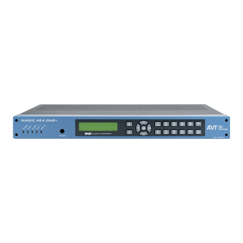
AVT MAGIC AE1 DAB+ Mounting instructions
AVT
AVT MAGIC AD1 ETI User manual

AVT
AVT MAGIC AE4 User manual

AVT
AVT MAGIC AE1 DAB+ User manual
AVT
AVT CVT-SDI-MAV User manual

AVT
AVT MAGIC EEC Mounting instructions