Avtron HS6M User manual

HS6M 1
8901 E. PLEASANT VALLEY ROAD
•
INDEPENDENCE, OHIO 44131-5508
TELEPHONE: (1) 216-642-1230
•
FAX: (1) 216-642-6037
E-MAIL:[email protected]
•
WEB: www.avtronencoders.com
Nidec-Avtron Makes the Most Reliable Encoders in the World
Encoder Instructions
MODEL
HS6M
HOLLOW SHAFT 6-15mm
DESCRIPTION
The Avtron Model HS6M is a light mill duty absolute encoder. It
expresses the position of rotation as an output message or value.
HS6M can measure a single turn of rotation or multiple rotations.
The HS6M measures the shaft rotation and position without the need
for external power or internal batteries or capacitors through its
innovative Wiegand wire energy system. The HS6M operates down
to zero speed and can be used for both control and instrumentation
applications.
CAUTION
Do not utilize HS6M in hazardous locations which
require ATEX, UL, CUL, CSA, or other explosion protection
certification. AV6M is not certified for hazardous
locations.
When mounted to a machine shaft, the HS6M design eliminates the
need for shaft couplings, adapter flanges, or accessory mounting
faces. The clamping collar holds the HS6M in place.
For larger bore/ larger frame size units, shaft inserts are available
to resize from native bores to smaller sizes. An anti-rotation arm
prevents housing rotation while allowing for shaft end float.
The HS6M utilizes magnetic sensors. This proven technology is ideal
for rugged environments since it is immune to many contaminants
that cause optical encoders to fail.
SAFETY
The HS6M is not considered as a safety device and is not suitable for
connection into a safety system.
CAUTION
Be careful not to damage clamping fingers of hollow
shaft during handling. Do not tighten clamping collar
before installation onto motor shaft.
WARNING
Installation should be performed only by qualified
personnel. Safety precautions must be taken to ensure
machinery cannot rotate and all sources of power are
removed during installation.
INSTALLATION
Refer to the back page of these instructions for outline and mounting
dimensions.
HS6M PART NUMBERS AND AVAILABLE OPTIONS
Model Bus Housing Bore Size Turns/
bits
PPR/bits
per turn Connector Mounting
Style Output IP
Rating
Special
Option
HS6M A-
Analog
C-
CANOpen
D-
DeviceNet
J-
J1939
S-
SSI
1- 58mm
3- 36.5mm
7- 42mm
L-
6mm
M-
8mm
N-
10mm
P-
12mm
R-
15mm
Z-
All metric
sizes
X-
0/0-
single turn
A- 16/4
(analog)
2-
4096/12
3-
8192/13
5-
32768/15
2- 4096/12*
3- 8192/13
*use ‘2’ also for
analog output
A-
1xM12/5 pin
C-
M12 x3 pin
E-
1xM12/8 pin
F-
M23/12 pin
K-
3x cable entry
W-
Cable, 1m
E- EOS only
Digital
1-
Binary
2-
Gray
Analog
3-
V output
0-5V
4-
V output
0-10V
5-
I Output
4-20mA
6-
I Output
0-20mA
X-
no shaft seal,
IP54, aluminum
+ steel housing
A-
IP65 seals,
aluminum + steel
housing
K-
IP69K stainless
housing
000-
none
9xx-
special
cable
length
xx=length
*0.3m
001-
pushbutton
setpoints
HOUSING COMPATIBILITY
Housing Bore Size IP/Sealing
1M, N, P, R, Z A, K
3 L X, A
7M, N, P A
STANDARD CONNECTORS & OUTPUT FORMATS
Bus Code Connectors Output
Analog A A, W 3, 4, 5, 6
CANOpen C A, W 1
DeviceNet D A, W 1
J1939 J A, W 1
SSI S E, F, W 1, 2

HS6M 2
Equipment needed for installation
Supplied:
HS6M Encoder
Anti-Rotation Tether
Optional:
Shaft Sizing Insert
Not Supplied:
Wrenches
Dial Indicator Gauge
Caliper Gauge
The hollow shaft HS6M design eliminates the potential for coupling
failures from misalignment, however, excessive housing movement
(wobble) may cause undesirable vibrations and bearing damage.
The higher the RPM, the more severe the vibration will be from
housing movement. In a typical installation a housing movement of
0.004” [0.1mm] TIR or less (as measured at the outside diameter of
the main encoder body) will not have an adverse effect.
1) Disconnect power from equipment and encoder cable.
2) Use caliper gauge to verify motor shaft is proper diameter and
within allowable tolerances: +0.000”, -0.0005”
[+0.00, -0.013mm].
3) Clean machine shaft of any dirt and remove any burrs.
4) Use dial indicator gauge to verify the motor shaft: Total
Indicated Runout (TIR) <0.002” [0.05mm].
5) Install the anti-rotation bracket tether to the face of the encoder
included with the tether.
6) Loosen clamping collar screws.
7) Test Fitting: carefully slide the encoder onto the shaft to verify
fit. Ensure a minimum of 1/16” [1mm] between encoder and
mounting surface. DO NOT FORCE. Encoder should slide on
easily. If the encoder does not fit easily, remove it, verify shaft
size, and check for burrs and shaft damage.
8) Slide the HS6M onto the shaft. Ensure minimum insertion
requirements shown on drawing page are met.
9) Tighten screws on clamping collar evenly until snug, then
tighten each screw as follows:
For bore sizes up to 1” [25mm] 38 in-lb [4.3 Nm]
For bore sizes >1” [25mm] 66 in-lb [7.5 Nm]
DO NOT USE A STANDARD RIGHT ANGLE WRENCH. Use only a
T-handle hex wrench or torque wrench with hex bit.
10) Secure free end(s) of the anti-rotation bracket to frame using
bolt or T-bolt provided. The bracket should be parallel to the
encoder face, 90 degrees to the shaft to avoid encoder bearing
damage. Use additional washers as needed to ensure the
tether is parallel to the encoder face.
12) Turn shaft by hand and verify the shaft turns freely and does
not produce excessive runout/wobble of the encoder (<0.005”
TIR [0.13mm], Total Indicated Runout.) Ensure the tether arm is
secure and the encoder body cannot rotate.
13) Connect cable as shown in wiring diagram.
14) Apply power to the encoder.
15) Rotate the shaft by hand, or using jog mode of the speed
controller and verify proper direction and position output.
ENVIRONMENTAL CONSIDERATIONS
Follow these steps to reduce potential problems:
1) Always mount connection points, conduit couplings, junction
boxes, etc., lower than actual encoder.
2) For washdown areas, shroud or otherwise cover the encoder to
prevent direct water spray. Do not attach the shroud directly to
the encoder.
REPAIRS
REMOVAL INSTRUCTIONS:
1. Unbolt tether arm from mounting point(s) on motor.
2. Loosen clamping collar screw(s).
3. Slide the encoder off the motor.
REPLACING PARTS
The HS6M has two items that are user-replacable in the field in
case of damage, or to change the encoder electrical or mechanical
interface:
1. Shaft sizing insert: Simply slide the insert out of the HS6M and
replace it with the new bore size insert. Insert should remove
and install with modest force-do not pound the insert into the
HS6M.
2. Tether system: To replace the tether system, remove the
retaining screw(s), then replace with the new tether.
CAUTION
Do not attempt to remove, service, or adjust any of the
internal components of the HS6M.
INSTALLATION
Refer to the back page of these instructions for outline and mounting
dimensions.
Equipment needed for installation
Supplied:
Encoder
Optional:
(none)
Not Supplied:
Open Wrenches, Hex Wrenches, Dial Indicator Gauge
Caliper Gauge, Mounting Screws
WIRING INSTRUCTIONS
CAUTION
Remove power before wiring.
Interconnecting cables specified in the wire selection chart are
based on typical applications. Refer to the system drawing for
specific cable requirements where applicable.
Physical properties of cable such as abrasion, temperature, tensile
strength, solvents, etc., are dictated by the specific application and
communications bus. Do not use unshielded cable. Ground one end
(only) of the shield to earth ground.
Do not run encoder wiring parallel to power cable wiring for
extended distances, and do not wrap encoder cable around power
cables.
TROUBLESHOOTING:
If the controller indicates a loss of encoder fault, check the encoder
power supply at the encoder. If power is present at the encoder,
check polarity. If the wiring appears correct and in good shape,
test the wiring by replacing the HS6M. If the controller still shows
encoder loss/fault, then the wiring is faulty and should be repaired or
replaced.
An oscilloscope can also be used to verify output of the HS6M
encoder at the encoder connector itself and at the drive/ controller
cabinet. Depending on the communication method, signals will vary
but the oscilliscope should show the output signals varying. Keep in
mind that SSI and Profibus DP are master-slave systems and require
the controller to signal the encoder to transmit position.
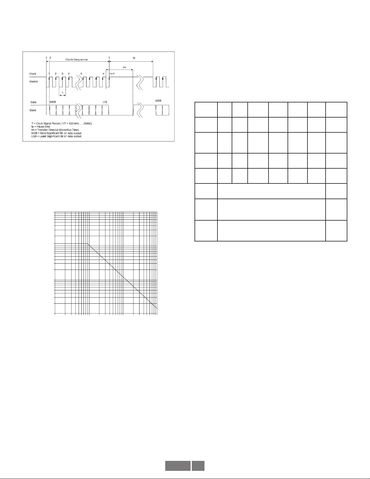
SSI TROUBLESHOOTING
For SSI, monitor the clock input line to ensure the controller is
triggering the encoder to send position. The clock should obey the
signal requirements shown in the SSI signal section, and should
appear as a rapid set of transitions on the clock line. The encoder
data transmit lines should change state as data is clocked out. Note
that the varying binary patterns representating position can produce
pulses of varying width--this is normal.
PROFIBUS-DP TROUBLESHOOTING

HS6M 3
Note that CANOpen units with a hardware connection cap are
typically set to 20K default baud rate. Not all master devices
support 20K, so the power-up message may not be displayed.
Check the baud rate and node address on the connection cap.
ANALOG TROUBLESHOOTING
For analog output, a multimeter can be used to measure the output
signal. Disconnect the encoder outputs (but maintain the power
connection) to ensure no interference from field wiring and measure
the output voltage or current directly at the encoder depending
on the output style selected. Rotating the shaft should produce a
change in output value.
For analog output: If the output is within the expected range
but does not seem to change, the analog value may have been
accidently scaled to a tiny fraction of a revolution or such a huge
number of turns that the output change cannot be detected.
Connect both Set End Point 1 and Set End Point 2 to +Vs for 1
1 second or more, then connect them to ground or no connection.
The encoder will be reset to use the full scale factory default with
the output and position set to the mid-point of the full scale. Now
monitor output voltage or current while rotating. You should observe
a voltage or current change. Now follow the instructions in the
analog section to properly reset the analog minimum and maximum
values.
Viewing on oscilliscope: for Profibus DP, the transmit and receive
signal pairs should change state rapidly as the controller transmits
messages to the encoder and the encoder replies. Transmission
rates vary, but these messages can be extremely short and typically
require scope triggering to spot them.
For Profibus DP, ensure termination resistors are in place (or
switched on) at each end of the cabling system, and that no
termination resistors are in placed or activated in the middle of
the system. Remove the connections to the master controller and
all devices, or power down all devices. Measure the resistance
between the communication wires. The value should be ~1/2 of the
termination resistor value on the network. If the resistance is greater
than the limit, a termination resistor is missing from the network. If
the resistance is less than the limit, there are incorrect termination
resistors switched on or connected to the system.
CANOPEN TROUBLESHOOTING
For CANOpen: disconnect the power connection, then ensure there
are no short circuits between any of the signal or power wires or
shield.
Viewing on oscilliscope: for CANOpen the transmit and receive
signal pairs should change state rapidly as the controller transmits
messages to the encoder and the encoder replies. Transmission
rates vary, but these messages can be extremely short and typically
require scope triggering to spot them.
For CANOpen, ensure termination resistors are in place (or switched
on) at each end of the cabling system, and that no termination
resistors are in placed or activated in the middle of the system.
Remove the connections to the master controller and all devices,
or power down all devices. Measure the resistance between the
communication wires [Example CANOpen-measure between CAN_L
and CAN_H]. The value should be ~1/2 of the termination resistor
value on the network. For CANOpen, this value should be >50 ohms,
<65 ohms. If the resistance is greater than the limit, a termination
resistor is missing from the network. If the resistance is less than
the limit, there are incorrect termination resistors switched on or
connected to the system.
Some housing styles include a two-color diagnostic LED. Red
indicates an error, Green indicates run status. During normal
operation, the encoder LED should be continously green. Flash
patterns indicate activity as follows:
RED - Error
Flickering - (Autobitrate/LSS services are in process)
Blinking - Configuration error
1) Flash - CAN bus frame error
2) Flashes - CAN guard timing or heartbeat error
3) Flashes - Sync message timeout
4) Flashes - PDO message timeout
ON - CAN Controller is in bus off state
GREEN - Run
Flickering - (Autobitrate/LSS services are in process)
Blinking - Encoder is in preoperational mode
1) Flash - Encoder is in stopped mode
3) Flashes - Software download in progress
ON - Encoder is operating normally with no errors
Nidec-Avtron recommends the use of a simple no-cost debugging
tool such as PCAN View.
Ensure the device is set to the proper baud rate (connection cap, or
for units with no connection cap, via software)
Ensure the device is set to the proper node address (connection cap
or for units with no connection cap, via software)
The encoder will power-up in the pre-operational mode.
The message it will issue is:
ID: 0x07nn 0x00
If you cannot see this message, try power cycling the device.

HS6M 4
ELECTRICAL SPECIFICATIONS
A. Operating Power (Vin = +Vs)
.........1. Voltage & Current
..............Analog V Out............ 12-30VDC; 15mA @ 24V
..............Analog I Out............. 15-30VDC; 40mA @ 24V
..............CANOpen................. 10-30VDC; 230mA @ 10V, 100mA @24V
..............DeviceNet................ 10-30VDC; 230mA @ 10V, 100mA @24V
..............J1939...................... 10-30VDC; 230mA @ 10V, 100mA @24V
..............Profibus DP.............. 10-30VDC; 230mA @ 10V, 100mA @24V
..............SSI .......................... 5-30VDC; 125mA @ 5VDC, 30mA @ 24V
.........2. Total Current............. as above plus cable load
B. Output Format
.........1. Analog Voltage.......... 0.5-4.5V; 0-5V; 0.5-9.5V; 0-10V
..............Current .................... 0-20mA or 4-20mA
.........2. SSI ........................... 100kHz-2mHz, set by master clock speed
.........3. CANOpen.................. 20kBaud to 1MBaud, node 0-127
.............................................. Default 125k, node 32 (0x20) -w/o connection cap
Default 20k, node 01 (0x01) -w/connection cap
.........4. DeviceNet................. 125kHz-500kHz, MAC-ID 0-63
.............................................. Default 125k, node 63 (3FH) -w/o connection cap
.........5. Profibus DP .............. 9.6KBaud to 12MBaud, node 0-99
.............................................. Default Auto-Baud, node 00 (00H)
.............................................. DPV1 (master/slave standard)
.............................................. DPV2 (isochronous, optional)
C. Direction Counting ............. Default up for CCW rotation as viewed
.............................................. from the back of the encoder
D. Counts Per Turn ................. 4096 - 8192 (12 - 13 bits)
E. Maximum Turns ................. 4096 - 32768 (12 - 15 bits)
F. Line Driver Specs ............... See table
G. Connectors........................ See connector options on page 1
H. Accuracy ........................... +/-0.35 deg (+/-21 arc-min) Analog Linearity: 0.15%
MECHANICAL
A. Shaft Inertia....................... 0.18lb-in-sec2 [315 g-cm2 (dyn)]
B. Acceleration....................... 6000 RPM/Sec. Max.
C. Speed................................ 6000 RPM Max
.............................................. 12000 RPM Max. w/o seals, not recommended
D. Weight............................... 0.33-0.4 lbs [150-180g]
E. Vibration any orientation .... 10 Gs, 5-2000 Hz
.............................................. 30 Gs, 5-2000 Hz
F. Shock any orientation ........ 200 Gs 3mSec
.............................................. 300 Gs 6mSec, flanges “6”, “7”
G. Shaft Load......................... 25bs Radial (110N) Max.
.............................................. 9bs Axial (40N) Max.
.............................................. 40lbs Radial (180N) Max., flanges “6”, “7”
.............................................. 40lbs Axial (180N) Max., flange “6”, “7”
ENVIRONMENTAL
Solid cast aluminum housing
Solid stainless steel housing optional
Operating Temperature.......... -30°C to +85°C.
Finish .................................... Powder Coat. Resists mild acids, bases, salt water
.............................................. & hydrocarbons
Housing Size Bore Range Min Insertion Max Insertion
36mm 6mm 16mm 18mm
42mm 8-12mm 16mm 18mm
58mm 8-15mm 25mm 30mm
BUS OPTIONS
Electrical
Specifications Analog CANOpen DeviceNet J1939 Profibus SSI Units
Input Voltage 12-30V 10-30V TBD 10-30V 10-30V 10-30V VDC
Cable Drive Capacity NA 8200’
[2500m]
1650’
[500m]** TBD 4000’
[1200m]
4000’
[1200m] feet
Protection
Reverse
Voltage yes yes yes yes yes yes
Short
Circuit yes yes yes yes yes yes
Transient yes yes yes yes yes yes
All cable lengths shown with optimal cable and minimum supported baud rate:
SSI: @100kbaud w/24 AWG, 52.5 pF/meter (16 pF/foot)
DeviceNet: Using main cable (round, large diameter)
CANOpen: @20kbaud
Profibus DP: 9.6Kbaud, 150ohm cable, <10pf/ft

HS6M 5
SSI Protocol “S”
The SSI Protocol “S” provides a clocked set of data bits that
represent the encoder position (in turns and within 1 turn). Each bit
is output by the encoder as the clock input transitions.
Preferred cable: Twisted pair with individual and overall shield
grounded at one end only. 24 AWG, copper conductor, capacitance of
52.5 pF/meter (16 pF/foot) terminated in a 100 Ohm resistive load.
Note that resistive losses in long cables may decrease actual voltage
(+Vs) available at the encoder; larger conductors can be used or the
encoder can be powered locally and signal GND brought through the
cable. Maximum transmission speed is limited by cable length as
shown in the figure below.
For more details on SSI, consult Wikipedia:
http://en.wikipedia.org/wiki/Synchronous_Serial_Interface
Set Zero
(input, ACTIVE HIGH, Falling Edge, 10K resistance)
To set the encoder count value to zero, raise Set Zero> 10V, < Vs for
more than 1 second. Upon the Set Zero signal returning to logic zero
(falling edge), the encoder count value will be set to zero.
Set Direction
(input, 10K resistance)
For input logic zero or no connection, the encoder will count UP for
CCW rotation as viewed from the rear end of the encoder.
For input logic 1 (>10V, <Vs), the encoder will count DOWN for CCW
rotation as viewed from the rear of the encoder.
Analog Protocol “A”
The analog protocol provides a steady-state analog output which
represents the encoder position over a portion of a turn or any
portion of a turn plus a number of turns. The factory default is 0-16
turns = min/max output. This can be modified by using the Set
Lower and Set Upper End Point inputs similar to most electronic
cam-setting systems (described below.)
Preferred cable: Overall shield grounded at one end only. Twisted
pair cable acceptable but not required. Note that resistive losses
in long cables may decrease actual voltage (+Vs) available at the
encoder; larger conductors can be used or the encoder can be
powered locally and signal GND brought through the cable.
Output 0-
5V
0-
10V
0.5-
4.5V
0.5-
9.5V
4-
20mA
0-
20mA Units
Signal
Code “3” “4” “7” “8” “5” “6”
Min.
Supply
Voltage
12V 12V 12V 12V 15V 15V Vdc
Min.
Load 10k 10k 10k 10k 0 0 ohms
Max.
Load Any Any Any Any 500 500 ohms
Settle
Time 80mS mS
Min.
Travel
Turns
0.06 turns /22.5 deg. Turns/
Deg.
Max.
Travel
Turns
65536 turns Turns
Set Lower End Point 1
(input, ACTIVE HIGH, Falling Edge, 10K resistance)
To set the encoder output to the minimum value at the present
position of rotation, raise Set Lower End Point 1> 10V, < Vs for more
than 1 second. Upon the Set Lower End Point 1 signal returning
to logic zero (falling edge), the encoder output will be set to the
minimum output shown in the output table.
Set Upper End Point 2 (input, ACTIVE HIGH, Falling Edge, 10K
resistance)
To set the encoder output to the maximum value at the present
position of rotation, raise Set Upper End Point 2> 10V, < Vs for more
than 1 second. Upon the Set Upper End Point 2 signal returning
to logic zero (falling edge), the encoder output will be set to the
maximum output shown in the output table.
Reset Upper and Lower End Points to Factory Default (16 turn
scaling)
Restore Factory Endpoint Settings (End Point 1, 2)
(input, ACTIVE HIGH, Falling Edge, 10K resistance)
Raise both Set Lower End Point 1 and Set Upper End Point
2> 10V, < Vs for more than 1 second. Upon both signals returning
to logic zero, the encoder output will be reset to the factory default
scaling of maximum output over 16 turns (only applies to the MT
option, and the present position and the encoder will be set to the
mid-point (8 turns) = 1/2 of the maximum output.
10K
10K
1K
100
10
1.2K
100K 1M 10M
DATA SIGNALING RATE - bit’s
Cable Lenght versus data signaling rate
CABLE LENGTH - METERS

HS6M 6
CANOpen Protocol “C”
The CANOpen protocol provides a set of data bits inside a CANOpen
message that represent the encoder position (in turns and within 1
turn).
CANOpen may be wired in several different configurations, but the
most common is a “Trunk and Drop Line” configuration. The trunk
message cable must be terminated at each end with 120 ohm
resistors. Note that CANOpen also offers the option to carry device
power to each encoder through an additional cable pair of wires.
Preferred cable: Twisted pair with individual pair and overall shields.
Communication pair: 24 AWG, copper conductor, capacitance of
50 pF/meter (15 pF/foot) terminated in a 120 Ohm resistive load.
Power pair: 22AWG copper conductor, 17ohms/1000 ft [55 ohms/
km]. Note that resistive losses in long cables may decrease actual
voltage (+Vs) available at the encoder; larger conductors can be
used or the encoder can be powered locally and signal GND brought
through the cable. Maximum transmission speed is limited by cable
length and number of devices as shown in the figures below.
Nidec-Avtron recommends the use of a simple no-cost debugging
tool such as PCAN View.
For more details on CANOpen, consult the CiA, CANOpen in
Automation:
www.can-cia.org
Network
Baud
Rate
1M 500K 250K 125K 50K 20K Units
Max.
Length
65
[20]
325
[100]
800
[250]
1600
[500]
3250
[1000]
8200
[2500]
ft
[m]
Max.
Single
Tap
Length
1
[0.3]
15
[5]
15
[5]
15
[5]
200
[60]
500
[150]
ft
[m]
Max.
Total Tap
Length
5
[1.5]
100
[30]
200
[60]
400
[120]
1000
[300]
2500
[750]
ft
[m]
Min. Tap
to Tap
Length
-
[-]
20
[6]
20
[6]
20
[6]
240
[72]
600
[180]
ft
[m]
Setting Node Number, Baud Rate & Termination Resistor
NOTE: Units with hardware connection caps cannot accept
software-commanded address, baud rate or termination resistor
changes. These must be made using the switches in the connection
cap. Before commencing any changes, check for a connection cap.
It is secured to the rear of the encoder with 2 or 3 screws and due
to snug fit will require a strong pull to remove it after removing the
screws.
NOTE: Any changes to baud rate, node number, or resistor will not
take effect until the encoder is reset (typically power cycled).
Power-Up Sequence
The encoder will power-up in the pre-operational mode.
The message it will issue is:
ID: 0x07nn 0x00
nn=node number, typically:
0x01 for units with connection cap including hardware node and
baud rate selection. (software commands will not change node)
0x20 is the factory default for units with software-selectable
addressing. (software commands can change node number)
Setting Node Number:
To set the node number: write SDO object 0x3000 using command
0x22. The encoder internally adds 1 to the written value.
Example, encoder at node 20, change node address to 02:
ID: 0x620 0x22 0x00 0x30 0x00 0x01 0x00 0x00 0x00
Setting Baud Rate:
To set the baud rate: write the baud code to SDO object 0x3001.
Example, encoder at node 20, change baud rate to 125K = 0x03
ID: 0x620 0x22 0x01 0x30 0x00 0x03 0x00 0x00
Network
Baud
Rate 1M 500K 250K 125K 50K 20K
Baud
Code 07h 05h 04h 03h 01h 00h
To enable the termination resistor: write 01 to SDO object 3002h.
Ensure any devices on the bus power up at least 700mS after the
encoder with the termination resistor activated.
Saving Changes (Required):
To save baud rate/node/resistor changes, write 0x55 0xAA 0xAA
0x55 to SDO object 0x2300
Example, encoder at node 20, store changes
ID: 0x620 0x22 0x00 0x23 0x00 0x55 0xAA 0xAA 0x55
Cycle power after saving changes.
Measuring Position, Speed, and Acceleration
To read position and speed feedback into your device (Acceleration
measurement is not supported.): Following the instructions for your
master/scanner module for the CANOpen network, load the encoder
EDS file into your configuration. Assign it to the correct node
number. Store the configuration to the scanner module.
All of the position data and other parameters will be read by
the scanner module and placed in registers identified in the
configuration package.
Reading data without using the EDS file:
To read position: read SDO object 0x2000 (32 bit unsigned) or SDO
object 0x6004.

HS6M 7
Speed measurement is deactivated by default.
To enable speed measurement: write 0x01 to SDO object 0x3010,
subindex 1, and write the speed modulus to subindex 2.
To read the speed after activation: read SDO object 0x3011 (8 bit
unsigned) or SDO object 0x6030.
Acceleration measurement is not supported. SDO object 0x3021
and 0x6040h are reserved for future use but do not indicate
acceleration at this time.
Setting Polling, Cyclic and Sync Mode
Polling, cycling and sync mode are supported by the encoder; use
the parameters supplied in the EDS file to set the appropriate mode.
Store the resulting configuration into the scanner module.
Storing/Saving Encoder Parameters
To store the current encoder operating parameters into non-volatile
memory:
Write 0x55 0xAA 0xAA 0x55 to SDO object 0x2300
Example, encoder at node 20, store changes
ID: 0x620 0x22 0x00 0x23 0x00 0x55 0xAA 0xAA 0x55
No reset is triggered.
Cycle power after saving changes to parameters.
Other Parameters
Contact Nidec Avtron for additional parameters, diagnostic registers,
cam and programmable limit switch functionality and other
advanced features.

HS6M 8
DeviceNet Protocol “D”
The DeviceNet protocol provides a set of data bits inside a DeviceNet
message that represent the encoder position (in turns and within 1
turn).
DeviceNet may be wired in several different configurations, but the
most common is a “Trunk and Drop Line” configuration. The trunk
message cable must be terminated at each end with 120 ohm
resistors. Note that DeviceNet also offers the option to carry device
power to each encoder through an additional cable pair of wires.
Preferred cable: Nidec Avtron recommends structured DeviceNet
wiring systems, available from a broad range of vendors. Large
diameter main, small diameter round cable, as well as flat cabling
systems are all acceptable.
For more details on DeviceNet, consult the Open DeviceNet Vendor’s
Association (ODVA):
www.odva.org
Network
Baud
Rate
500K 250K 125K Units
Max.
Length*
325
[100]
800
[250]
1600
[500]
ft
[m]
Max.
Single
Tap
Length
15
[5]
15
[5]
15
[5]
ft
[m]
Max.
Total
Tap
Length
100
[30]
200
[60]
400
[120]
ft
[m]
Min. Tap
to Tap
Length
20
[6]
20
[6]
20
[6]
ft
[m]
Setting Node (MAC-ID), Baud Rate & Termination Resistor
To set the node MAC-ID number: write attribute 6Fh (byte).
To set the baud rate: write the baud code to attribute 6Eh (byte).
Network
Baud
Rate
500K 250K 125K Units
Baud
Code 02h 01h 00h
Remember, these values are not stored permanently and do not take
effect until they are written to EEPROM. If power is cycled before the
values are stored, the encoder will default to the values previously
stored in EEPROM.
To enable the termination resistor: write 01 to attribute 67h. Ensure
any devices on the bus power up at least 700mS after the encoder
with the termination resistor activated.
Measuring Position, Speed, and Acceleration
Only position feedback is supported in DeviceNet; acceleration and
speed are not available at this time.
To read position feedback into your device: Following the
instructions for your master/scanner module for the DeviceNet
network, load the encoder EDS file into your configuration. Assign it
to the correct MAC-ID node number. Store the configuration to the
scanner module.
All of the position data and other parameters will be read by
the scanner module and placed in registers identified in the
configuration package.
Setting Polling, Cyclic and Sync Mode
Polling, cycling and sync mode are supported by the encoder; use
the parameters supplied in the EDS file to set the appropriate mode.
Store the resulting configuration into the scanner module.
Storing/Saving Encoder Parameters to EEPROM
To store the current encoder operating parameters into non-volatile
memory:
Send message [(master MAC-ID) 32h 23h 01h]. A new allocation is
then required to resume receiving position values from the encoder.
Other Parameters
Contact Nidec-Avtron or review the EDS file for additional
parameters, diagnostic registers, cam and programmable limit
switch functionality and other advanced features.

HS6M 9
Profibus DP Protocol “P”
Profibus DP is typically a master-slave network-the master/scanner
device gathers data from each (slave) device on the bus. Avtron
encoders are Profibus DP slave devices.
Profibus may be wired in several different configurations, but the
most common is a “Daisy-Chain” configuration. The master/scanner
device may be located at any point along the bus. The cable must
be terminated at each end with 150 ohm resistors. Note that
Profibus DP also offers the option to carry device power to each
encoder through an additional cable pair of wires.
Preferred cable: Nidec Avtron recommends structured Profibus DP
wiring systems, available from a broad range of vendors.
For more details on Profibus, consult the Profibus Users Association
(PI):
http://www.profibus.com/
Number
of
Nodes
2 16 32 64 Units
Max.
Overall
Cable
Length*
750
[229]
690
[210]
640
[190]
560
[170]
ft
[m]
Network
Baud
Rate
12M
6M
3M
1.5M 500K 187.5K 93.75K
45.45K
19.2K
9.6K
Units
Max.
Length*
325
[100]
650
[200]
1300
[400]
3250
[1000]
4000
[1200]
ft
[m]
*Using Profibus standard cable, 150 ohm impedance 3-20mHz,
<30pf/m, <110 ohms/km loop resistance
Setting Station/Node, Baud Rate & Termination Resistor
To set the node number: use the rotating switches in the connection
cap. The format is decimal, from 0-99 (ten’s switch and one’s
switch). Software/master address changes are not supported.
NOTE: Each device must have a unique node address, and this
address must be different than the master/scanner module.
Profibus DP baud rate is auto-detected by the encoder, no settings
are required. 12 MBaud, 6 MBaud, 3 MBaud, 1.5 MBaud, 500 kBaud,
187.5 kBaud, 93.75 kBaud, 45.45 kBaud, 19.2 kBaud, 9.6 kBaud are
all supported.
To enable the termination resistor: Move the switch “R” to the “On”
Position on the connection board. The termination resistor should
be turned on/enabled when the encoder is the last/only device on
the bus. Note that standard 9 pin DIN connectors used for Profibus
DP also offer a termination resistor. Be sure NOT to enable both the
encoder termination resistor and the 9-pin connector resistor, use
one or the other for an encoder at the end of a bus.
Measuring Position, Speed, and Acceleration
To read position and speed feedback into your device (Acceleration
measurement is not supported.): Following the instructions for
your master/scanner module for the Profibus DP network, load the
encoder GSD file into your configuration. Assign it to the correct
node number. Store the configuration to the scanner module.
All of the position data and other parameters will be read by
the scanner module and placed in registers identified in the
configuration package.
For multiturn & single turn encoders: position data provided as
4 bytes, 32 bits: Format is little-endian (lowest bit = right-most
bit). Single-turn data/data within 1 turn is provided in the least-
significant bits. Multiturn data is provided directly “above” the
single turn data, bitwise. Example: 12 turns x 13 bits/turn encoder,
lowest 13 bits = position within one turn, next 12 bits (up to bit 25)
represent turns position data.
Setting Zero Position for Multiturn Encoders and Single turn
Encoders Using 32 Bit Feedback:
Write 1 to the highest bit (31)-write 128 (80H) to top-most-byte of
the position register.
For single turn encoders: position data can instead be provided as 2
bytes, 16 bits: Format is little-endian (lowest bit = right-most bit).
Setting Zero Position for Single turn Encoders Using 16 Bit
Feedback :
Write 1 to the highest bit (15)-write 128 (80H) to top-most-byte of
the position register.
Isochronous (Auto-Transmit) Mode
DPV2 Isochronous communication can be configured using the
optional DPV2 GSD file. Load the encoder GSD file into your master/
scanner software. Assign it to the correct node number. Store the
resulting configuration into the scanner module. Note many Profibus
master devices do not support isochronous mode-check the master
device manual before utilizing this encoder mode.
Other Parameters
Contact Nidec Avtron for additional parameters, diagnostic registers,
cam and programmable limit switch functionality and other
advanced features.

HS6M 10
CONNECTOR
OPTION
“W”
(Cable)
OPTION
“F”
M23
OPTION
“E”
M12
OPTION
“S”
(1x Cable Entry
Terminal)
SIGNAL
GND BLACK 12 1 1
+Vs RED 11 2 2
CLK+ GREEN 2 3 3
CLK- YELLOW 1 4 4
DAT+ GRAY 3 5 5
DAT- VIOLET 4 6 6
SET ZERO BLUE 9 7 7
SET DIRECTION BROWN 8 8 8
NC ORANGE 5
NC WHITE 6
NC 7
NC 10
REF
SIGNAL
GND
+Vs
CLK+
CLK-
DAT+
DAT-
SET ZERO
SET DIRECTION
NC
NC
NC
NC
* NOTE: Twisted pair cable required with overall shield; individual pair shielding recommended. Obey pairing as shown
Communication Bus “S”: SSI Pinout
CONNECTOR
OPTION
“W”
(Cable)
OPTION
“S”
(1x Cable
Entry)
SIGNAL
GND BLACK 4
+Vs RED 8
Set Upper End Point 2 WHITE 1
Set Lower End Point 1 BROWN 2
Analog Out GREEN 3
NC GRAY
NC VIOLET
NC BLUE
NC YELLOW
NC ORANGE
REF
SIGNAL
GND
+Vs
Set Upper End Point 2
Set Lower End Point 1
Analog In
NC
NC
NC
NC
NC
Communication Bus “A”: Analog Pinout
* Note: Overall shield required; twisted pair cable not required, pairs shown only for convenience
HS6M WIRING DIAGRAMS

HS6M 11
CONNECTOR
OPTION
“C”
M12x3
OPTION
“K”
(3x cable)
SIGNAL CONNECTOR Pin Terminal Point
GND (0V) 4 pin male 3 Any (-)
+Vs 1 Any (+)
Bus A in 5 pin male 2Leftmost A
Bus B in 4 Leftmost B
Bus A out** 5 pin female 2Rightmost A
Bus B out** 4 Rightmost B
REF
SIGNAL
GND (OV)
+Vs
Bus A out
Bus B out
Bus A in
Bus B in
* NOTE: Profibus cabling required. Obey pairing as shown
**If termination resistor “R” is enabled/”on”, bus out terminals are disabled
Communication Bus “P”: Profibus Pinout
HS6M WIRING DIAGRAMS
Power Supply
Bus In Bus Out

HS6M 12
CONNECTOR
OPTION
“W”
(Cable)
OPTION
“A”
(M12 / 5
pin)
SIGNAL
CAN_GND GREEN 1
CAN_V+ RED 2
CAN_H WHITE 4
CAN_L BROWN 5
GND YELLOW 3
REF
SIGNAL
CAN_GND
CAN_V+
CAN_H
CAN_L
GND
CANOpen Bus “C”
HS6M WIRING DIAGRAMS
* NOTE: Twisted pair cable required with individual and overall shields. Obey pairing as shown.
CONNECTOR
OPTION
“W”
(Cable)
OPTION
“A”
(M12 / 5
pin)
SIGNAL
NC 1
V+ RED 2
V-/GND BLACK 3
CAN_H WHITE 4
CAN_L BLUE 5
REF
SIGNAL
V+
V-/GND
CAN_H
CAN_L
DeviceNet Bus “D”
* NOTE: DeviceNet cable required. Obey pinouts and cable pairing as shown.

HS6M 13
HS6M, 36.5mm Housing “3”, Connector/Cable “W”
6mm bore “L”, IP54 Seals & Aluminum+Steel Enclosure “X”
All dimensions are in
mm [inches] approx.

HS6M 14
HS6M, 36.5mm Housing “3”, Connector M12 “A”,”E”
6mm bore “L”, IP65 Seals & Aluminum+Steel Enclosure “A”
All dimensions are in
mm [inches] approx.

HS6M 15
HS6M, 42mm Housing “7”, Connector M12, “A”, “E”
12mm bore “P”, IP65 Seals & Aluminum+Steel Enclosure “A”
All dimensions are in
mm [inches] approx.

HS6M 16
REV: 09/09/14
NIDEC AVTRON AUTOMATION CORPORATION
8901 E. PLEASANT VALLEY RD., INDEPENDENCE, OH 44131, U.S.A.
(1) 216.642.1230 | FAX (1) 216.642.6037 | www.avtronencoders.com
HS6M, 58mm Housing “1”, Connector M23 “F”
15mm bore “R”, IP65 Seals & Aluminum+Steel Enclosure “A”
Features and specifications subject to change without notice.
Avtron standard warranty applies. All dimensions are in mm [inches] approx.
Table of contents
Other Avtron Media Converter manuals

Avtron
Avtron SMARTSafe XR67 User manual

Avtron
Avtron AV85 User manual

Avtron
Avtron M6C-4 User manual

Avtron
Avtron XR56 SMARTSafe User manual

Avtron
Avtron SMARTSafe XR125 User manual

Avtron
Avtron AV45 Series User manual

Avtron
Avtron AV56A User manual

Avtron
Avtron SMARTSafe XR4F User manual

Avtron
Avtron HS4 User manual

Avtron
Avtron HS35M User manual

Avtron
Avtron HS35A User manual

Avtron
Avtron HS6A User manual

Avtron
Avtron XR56 SMARTSafe User manual

Avtron
Avtron SMARTach III AV850 User manual

Avtron
Avtron SHAFTach M585 User manual

Avtron
Avtron AV115 User manual

Avtron
Avtron M6-1 User manual

Avtron
Avtron AV6A Series User manual

Avtron
Avtron SMARTSafe XP5 User manual

Avtron
Avtron M3-3 User manual