OPERATING POWER (EACH OUTPUT)...................................
OUTPUT SIGNAL ......................................................................
PULSES PER REVOLUTION.....................................................
WAVE SHAPE ............................................................................
VOLTAGE OUTPUT....................................................................
OUTPUT PROTECTION ............................................................
FREQUENCY .............................................................................
MECHANICAL
SHAFT DIAMETER REQUIREMENTS....................................
SPEED RANGE .......................................................................
STARTING TORQUE................................................................
HUB INERTIA...........................................................................
ACCELERATION (MAX.)..........................................................
OPERATING TEMPERATURE ...................................................
WEIGHT .....................................................................................
15 V OPERATING VOLTAGE
12 TO 15 VDC AT APPROX. 70 mA (NO LOAD)
TWO CHANNELS IN QUADRATURE
(2-PHASE, BIDIRECTIONAL)
240, 360, 600, 1024, 1200, 2048 PPR STD.
— OTHERS AVAILABLE UPON REQUEST
SQUARE WAVE
HIGH: SUPPLY VOLTAGE MINUS 1 VOLT
(NO LOAD)
120 OHMS PULL-UP
LOW: 1.0 VOLT MAX.
50mA SINK
SHORT CIRCUIT PROTECTION TO COMMON
50 KHz MAX.
1.125 +.000/-.003 INCHES
0 TO 3600 RPM
3.9 OZ.-IN. (TYP.)
0.5 OZ.-IN.-SEC2
3000 RPM/SEC
0° TO 160°F AMBIENT
15 LBS.
24 V OPERATING VOLTAGE
24 VDC AT APPROX. 70 mA (NO LOAD)
TWO CHANNELS IN QUADRATURE
(2-PHASE, BIDIRECTIONAL)
240, 360, 600, 1024, 1200, 2048 PPR STD.
— OTHERS AVAILABLE UPON REQUEST
SQUARE WAVE
HIGH: SUPPLY VOLTAGE MINUS 1 VOLT
(NO LOAD)
330 OHMS PULL-UP
LOW: 1.0 VOLT MAX.
50mA SINK
SHORT CIRCUIT PROTECTION TO COMMON
50 KHz MAX.
1.125 +.000/-.003 INCHES
0 TO 3600 RPM
3.9 OZ.-IN. (TYP.)
0.5 OZ.-IN.-SEC2
3000 RPM/SEC
0° TO 160°F AMBIENT
15 LBS.
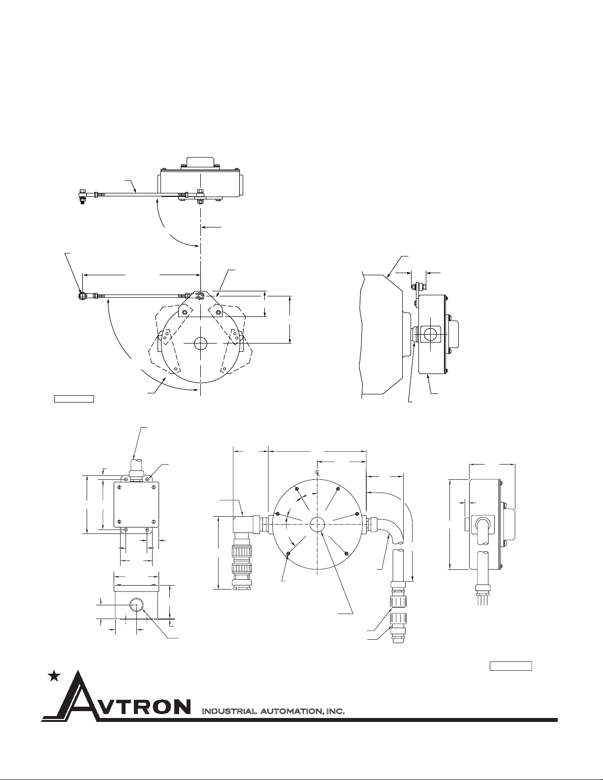
INSTALLATION
MACHINE SHAFT PREPARATION
Preparing the machine shaft prior to Pulse Generator instal-
lation is essential in providing an adequate barrier against
environmental contamination. In some cases, a separate stub
shaft (1.125" D x 4.5" long) will be installed on the motor. To
prepare the machine shaft that the M585 is to be installed on,
conduct the following procedures (see figures):
1. Remove from the M585 the four 1⁄4-20 UNC machine
screws which hold the end cap on the cover plate.
2. Remove the end cap, O-Ring, and wave spring, noting
the location of each to assist in reassembly.
CAUTION
SPANNER WRENCHES MUST BE USED DURING THE
FOLLOWING PROCEDURES. Using a substitute can distort
the 13⁄4" nut and damage the unit. Do not try to remove the
21⁄2" bearing locknut at any time.This locknut is factory adjusted
for optimum M585 performance.
NOTE
Two spanner wrenches, which are required for M585 installa-
tion, accommodate the 13⁄4" and 21⁄2" nuts found under the cap.
3. Holding the 21⁄2" bearing locknut, remove the 13⁄4" diame-
ter clamping nut and slide out the internal compression sleeve.
4. Verify that the compression sleeve can be installed by
hand on the shaft where the unit is to be installed. File any burrs
that obstruct sleeve installation and lightly oil the shaft.
5. If a keyway or flat exists on the shaft, provide a sealing
medium or true shaft back to round using metal putty or equal.
6. Return the compression sleeve to the M585 hub.
7. Thread the 13⁄4" clamping nut onto the M585 by hand until
resistance is felt. DO NOT TIGHTEN AT THIS TIME.
PULSE GENERATOR INSTALLATION
Installing the M585 and Anti-Rotation Arm:
1. The free end of the Anti-Rotation Arm must be secured
by the customer to a stationary member such as the floor or
machine frame. Refer to “Anti-Rotation Arm Mounting Guide-
lines” on the last page
for general require-
ments.
2. Based on the lo-
cation of the stationary
point and the guidelines
on page 4, attach the
1⁄4" thick mounting board
provided to one of five
places on the M585.
Use two 1⁄4-20 UNC by
3⁄4" long machine screws
provided.
3. Ensure that the
machine shaft is lightly
oiled. A packet of sili-
cone grease is provided
to lubricate the following
shaft seals: First, ALL
M585 types have an O-ring inside their hollow shafts at the mo-
tor end. In addition, in THRU SHAFT types, the clamping nut
has an O-ring on the inside, plus the outside of the clamping nut
requires lubrication for the radial lip seal per step 8b. Slide the
M585 onto the machine shaft, mounting board first. Ideally, the
M585 housing will be 1⁄2" to 1" from the motor or machine hous-
ing, but this may vary depending on the machine profile and the
anti-rotation arm clearance requirements. Consider shaft end
float when positioning the M585.
4a. FOR STUB SHAFT APPLICATIONS, place the M585
31⁄4" to 4" onto the shaft. The end of the machine shaft must ex-
tend completely through the M585 compression sleeve and be
approximately flush with the end of the 13⁄4" clamping nut.
4b. FOR THRU SHAFT APPLICATIONS, position the M585
as required.
5. Attach free end of the Anti-Rotation Arm to the
1⁄4" mounting board using the shoulder bolt provided.
6. Remove 13⁄4" clamping nut and apply liquid thread locker
to the threads. (Locktite grade 242, supplied, should be used in
most applications.)
NOTE
Where thread locker has been used, additional force is required
for M585 removal.
7. Replace 13⁄4" clamping nut and tighten so the gap is less
than or equal to 0.09", as shown in CLAMPING NUT sketch
(approx. 15-20 ft-lbs), holding the 21⁄2" bearing locknut in place.
Spanner wrenches are required for this operation.
8a. FOR STUB SHAFT INSTALLATIONS, replace the end
cap with the wave spring (loading spring) against the bearing
and the O-ring located in the cap groove. Secure the end cap
with the four 1⁄4-20 UNC machine screws previously removed.
Apply the supplied grade 242 Locktite to the screws when as-
sembling.
8b. FOR THRU SHAFT APPLICATIONS, prior to replac-
ing the end cap per step 8a, apply a small amount of silicone
grease (provided) to the seal surface on the 13⁄4" clamping nut.
The radial lip seal in the end cap will seal on this surface.
WIRING CONSIDERATIONS
For bidirectional operation of the SHAFTach™,
proper phasing of the two output channels is
important. Phase A channel leads phase B
channel for clockwise rotation as viewed from
the end-cap (anti-drive) end of the generator.
Interconnecting cables specified in the wiring
diagrams are based on typical applications.
Refer to the system drawing for specific cable
requirements where applicable.
Physical properties of cable such as abrasion,
temperature, tensile strength, solvents, etc.,
are dictated by the specific application. Gen-
eral electrical requirements are: stranded cop-
per, 22 thru 16 gauge, braid or foil with drain
wire, 0.05 MF maximum total mutual or direct
capacitance, outer sheath insulator, 1,000 ft.
max.
ENVIRONMENTAL
CONSIDERATIONS
Special attention is to be given to conduit runs, interconnection
wiring and NEMA type enclosure mounting. In those applications
where ambient temperatures are controlled within 40°F and high
humidity/washdown are not present, position the flexible conduit
with a slight sag to prevent any condensation from entering the
SHAFTach via conduit.
In harsh environments, which include temperature extremes, high
humidity, equipment washdown or atmosphere contamination,
extra care is required for interconnection. Follow these steps to
reduce potential problems:
1. Always mount connection points, conduit couplings, junc-
tion boxes, etc., lower than actual generator.
2. Venting of generator is beneficial. One method is to take
conduit run outside of hostile area where practical. (Applies to
conduit installations only.)
3. For washdown areas, shroud or otherwise cover the
SHAFTach to prevent direct water spray. Do not attach the shroud
directly to the generator.
4. Keep conduit outputs and axis of rotation horizontal.
5. Purging of SHAFTach should be reviewed with Avtron.
M585 SPECIFICATIONS
N
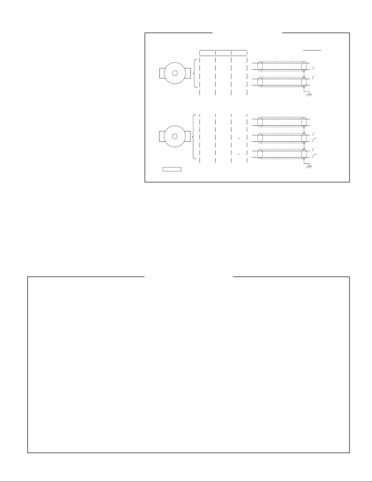
OUTPUT OPTIONS
CT
RED
BLUE
GREEN
BLACK
B
E
D
A
+V
B
A
COM
M585
FOR SINGLE ENDED
APPLICATIONS
CABLE BELDEN #8723
OR EQUIVALENT
OPERATING
VOLTAGE
0B
0A
COMMON
GROUND
FOR SINGLE ENDED APPLICATIONS
FUNCTION
GREEN
YELLOW
BLUE
GRAY
BLACK
RED
D
B
A
G
E
H
A
A
+V
COM
B
B
M585
FOR DIFFERENTIAL
APPLICATIONS
CABLE BELDEN #9773
OR EQUIVALENT
0A
OPERATING
VOLTAGE
COMMON
0A
0B
0B
GROUND
FOR DIFFERENTIAL APPLICATIONS
NOTE: 5’ FLEXIBLE CONDUIT STANDARD
FOR ALL OUTPUT OPTIONS
M585WD.MAC
WIRING DIAGRAM