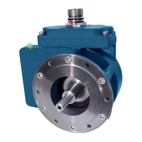
XR4F 3
VARIATION > ± 15%
PHASE A
PHASE B
MODIFICATION
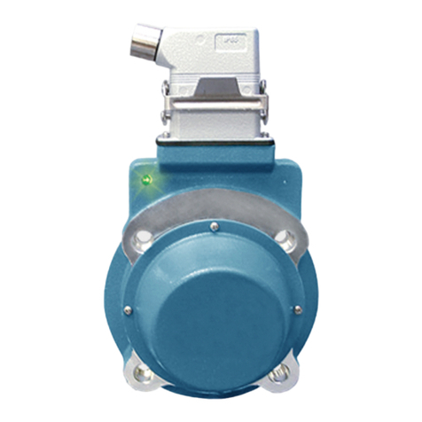
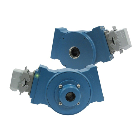
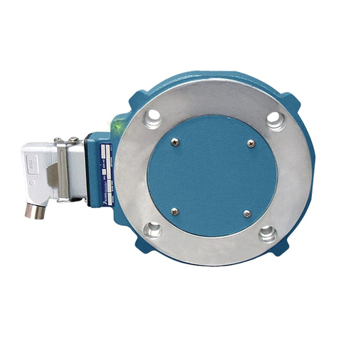
The XR4F can be modified to easily adapt to new applications.
CAUTION
Do not attempt to modify the electrical connector
options of the XR4F while located in a hazardous
location or atmosphere. Doing so may create a severe
spark hazard which can result to damage to property,
injury, or even death.
TO CHANGE ELECTRICAL CONNECTOR STYLE:
1. Remove electrical power and disconnect the mating plug.
2. Unscrew the (4) M5 screws (4mm hex).
3. Pull the connector header away from the encoder gently.
4. Disconnect the ribbon connector to the encoder body.
5. Connect the ribbon connector to the new connector header
6. Attach the new connector header to the encoder using the (4) M5
screws. Tighten to 30 in-lbs [3.4n-m]. Be sure the ribbon
connector fits in the open pocket under the header and is not
crushed or pinched by the connector header.
WIRING
CAUTION
Be sure to remove power before wiring the encoder.
Be sure to ground the cable shield: Avtron recommends
grounding the shield at the isolator module for Zone 1
applications or in the drive cabinet for Zone 2
applications. Cable should not be grounded multiple
places. An intrinsic safety ground is required at the
XRB1 Isolator Module.
CAUTION
SMARTSafe encoders include a local ground lug for
customer convenience and encoder frame grounding if
required to meet local electric code requirements or
site operator protection standards. This is NOT the
required XRB1 intrinsic safety ground connection
required for hazard protection against ignition of
explosive atmospheres! Wiring diagrams are shown in
the following pages.
Wiring diagrams are shown in the following pages.
CAUTION
Zone 1 and Zone 21 applications utilize the XRB1
isolator which requires an intrinsic safety ground
to provide hazard protection. Failure to connect this
ground, or providing an inadequate safety ground path
could result in an spark/ignition hazard which can
result in property damage, injury, or even death.
Refer to the wiring diagrams and pinout and phasing tables for
specific information on each option.
The XR4F can be wired for single phase or two phase, either with
or without complements, with or without markers. For bidirectional
operation, Phase A channel typically leads phase B channel for
clockwise shaft rotation as viewed from the anti-drive or accessory
end of the motor (XR4F mounting end). See pinout and phasing tables
for exceptions
NOTE
Wiring option “G” provides a pinout compatible with
NorthstarTM encoders, with a cable shield connection
on pin 10. Note that this option does not ground the
shield.
CORRECTIVE ACTION FOR PHASE REVERSAL
1) Remove Power.
2) Exchange wires on cable, either at encoder cable end,
or at speed controller end (but not both).
a) Single Ended 2 Phase Wiring (see wiring diagram)
Exchange A with B
b) Differential 2 Phase Wiring (see wiring diagram)
Exchange either A with A– in the phase A pair OR
B with B– in the phase B pair but NOT both.
3) Apply Power.
4) Verify encoder feedback is correct, using hand rotation
of shaft, or jog mode of the speed controller.
Interconnecting cables specified in the wire selection chart are
based on typical applications. Cable must be selected and installed
in accordance with IEC/EN60079-14 and IEC/EN60079-25. Physical
properties of cable such as abrasion, temperature, tensile strength,
solvents, etc., are dictated by the specific application. General
electrical requirements are: stranded copper, 20 through 16 AWG
(Industrial EPIC connector type options can use 14 AWG), each wire
pair individually shielded with braid or foil with drain wire, .05 uf of
maximum total mutual or direct capacitance, outer sheath insulator.
See specifications for maximum cable length. Stranded 20 AWG wire
should not be used for cable runs greater then 61 meters. If 20 AWG is
used with EPIC type connector options the wire ends should be tinned.
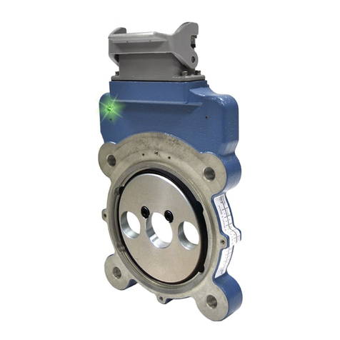
FAULT-CHECK
After power-up and the rotor position is checked by the sensor, the
Fault-Check LED will turn green.
If the adaptive electronics reach their adjustment limit for any reason,
the Fault-Check alarm and LED will notify the drive and operator of
an impending failure. The LED will turn red if the Adaptive Electronics
reach their adjustment limit. This output occurs before an actual
failure, allowing steps to be taken to replace the unit before it causes
unscheduled downtime. Fault-Check annunciation is available as an
“alarm” output through the connector (zone 2 configurations only) and
as an integral LED.
TROUBLESHOOTING
If the drive indicates a loss of encoder/tach fault and the XR4F
fault-check LED is not illuminated, check the encoder power supply.
If power is present, check polarity; one indicator of reversed power
supply is that all outputs will be high at the same time. If the drive
indicates encoder fault, but the LED shows GREEN, then check the
wiring between the drive and the encoder. If the wiring appears
correct and in good shape, test the wiring by replacing the XR4F. If the
new unit shows GREEN, and the drive still shows encoder loss/tach
fault, then the wiring is faulty and should be repaired or replaced.
If the alarm output and/or LED indicate a fault (RED) on a properly
mounted XR4F and the rotor is properly located, replace the XR4F.
An oscilloscope can also be used to verify proper output of the
XR4F encoder at the encoder connector itself and at the drive/
controller cabinet. If the outputs show large variations in the signals
at steady speed (jitter or “accordion effect”, see figure 5), replace any
magnetized material nearby with non-magnetic material (aluminum,
stainless) (shafts, etc). If variations persist, consider replacing with
super-shielded models, option -004.
