Avtron SMARTach III AV850 User manual

AV850 1
(OPTIONAL) LARGE MOTOR STATOR ADAPTER INSTALLATION
(Modification “700”,”704”)
For large frame GE CD motors Avtron offers a frame adapter to add an
8.5” C-face to the motor. To install the flange adapter:
1. Remove all existing adapters on the non-drive end of the motor.
2. Clean the motor flange.
3. Using the supplied hardware, bolt the flange adapter in place
(see Figure 1).
4. Apply anti-seize to the frame adapter C-face flange.
(OPTIONAL) INBOARD SEAL PLATE INSTALLATION
(Cover Plate “B” & “N”)
For installations where the AV850 will be mounted to an open frame
flange adapter, or other installation where the inner surface of the AV850
will not form a seal with the rear end bell of the motor, Avtron offers
inboard, through-shaft seal plate kits. These kits include a cover plate
and seal. See Table 3 for part numbers. To install the inboard through-
shaft seal plate kit:
1. Verify all components fit the motor shaft (rotor, V-ring seal, and
seal plate.
2. Slide V-ring seal onto motor shaft.
3. Apply a light coating of silicone lubricant or medium grade
machine oil to the outward face of the seal.
4. Use the seal plate to push the seal on the shaft; stop when the
seal plate contacts the motor face. Remove the seal plate and
push the V-ring seal an additional 0.09” [2.29mm] toward
motor.
Verify the V-ring seal is clear of the motor bearings and housing.
V-ring seal compression should be between 0.03” and 0.09”
[0.75mm-2.29mm] in final position when plate is reapplied.
5. Remove the double-stick tape protection. Align the bolt holes.
6. Stick the inner cover plate in place.
7. Mount rotor per instructions below, but increase axial position
from motor to rotor to 0.620” [15.75mm] (from 0.584”) to
accommodate the inner seal plate thickness. See Figure 3.
8. Mount remainder of AV850 per instructions on next page.
MAGNETIC SHIELD INSTALLATION
For top performance on older motors with magnetized shafts and frames
install the AV850 shield. The AV850 also has built-in shields attached to
the housing of every unit. The standard AV850 shield as provided will
fit shafts up to 3” [76mm]. For larger shafts, if desired, the shield can
be custom-cut by the customer to fit a larger bore (recommend +0.125”
[3.1mm] over shaft size), or the shield can be omitted, as its effectiveness
is reduced beyond a 3” bore size.
NOTE
For additional magnetic field protection, consider the -004
option for extra sensor shielding.
1. Remove the double-stick tape protection.
2. Align the bolt holes and edges with the motor C-face.
3. Stick the shield in place on the motor C-face or on top of any
inboard seal plate.
4. Install rotor as usual, but gage location from the shield.
See Figure 3.
The outer edge of the rotor may be damaged by scratches, severe
blows, and strong magnetic fields.
GENERAL
The Avtron Model AV850 SMARTach™ III is an incremental encoder
(also known as tachometer or rotary pulse generator), allowing operation
down to zero RPM. It provides a specific number of electrical Pulses Per
Revolution (PPR) that are proportional to a shaft’s revolution. The AV850
SMARTach III is a bearingless, couplingless, modular design, providing
unequaled reliability and mechanical performance.
The AV850 fits AC and DC motors with an 8.5” C (FC / 180) Face. Both
end-of-shaft and through shaft mountings are accommodated.
The AV850 Encoder consists of three or four parts: a rotor, a stator
housing, and one or two removable sensor modules. No gapping,
adjustment, or shimming is required!
An Avtron AV850 SMARTach III is equipped with one or two AV5 sensor
modules. Each module has a two-phase output (A, B) 90° out of phase,
with complements (A, B), (A Quad B Output), and a marker pulse
with complement (Z, Z). For applications which require more than 2
independent outputs, AV850 encoders may be stacked via the use of
shaft adapters (see Table 2 for part numbers). Two separate encoders
would be purchased.
Output resolution on the AV850 is determined by the sensor only. Unlike
older models, any PPR’s can be mixed and matched. Selection of the
rotor is based only on the shaft mounting requirements (and not PPR).
The AV5 removable sensor assembly has a diagnostic package that
includes Adaptive Electronics and a Fault-Check output. With this
package, the SMARTach III can maintain itself, and let you know if there
is a problem before the problem causes unscheduled downtime.
SECTION II: INSTALLATION
GENERAL
The motor must comply with NEMA MG1 for dimensions, face runout, and
shaft runout. Axial float or endplay must be less than +/-0.100” inch.
INSTALLATION HARDWARE
Installation hardware required is attached to each assembly.
Equipment needed for installation
Model: AV850 SMARTach™ III
8-1/2” FC FACE MOUNT MODULAR
Equipment Needed for Installation
Provided Optional Not Provided
AV850 Encoder
- Washer, Spring Lock
1/2 (4)
- Hex Hd. Cap Screw
1/2-13 x 3.00 (4)
Rotor
- Rotor Installation
Hardware Kit
- Anti-Seize
Compound (copper)
- Thread Locker (blue)
- A35226 Gauge or
A25355 M285/
AV850 Rotor
Gauge Block
- Inboard Through-
Shaft Seal Plate
- Outboard Through-
Shaft Seal Plate Kit
- Silicone Lubricant
or 20 Weight
Machine Oil
- Dead Blow Hammer
- Large Frame
Adapter Kit
(Modification “700”)
AV850 Shield Kit
(A35355)
- 3/4” Wrench
- Phillips Screwdriver
- 7/16” Nut Driver
- Dial Indicator
- Vernier Caliper
- 3/32” Hex Wrench
(T-Handle style) (thru
shaft rotors only)
- 3/16” Hex Wrench
(cam screw rotors only)
- 9/16” Wrench (end-of-
shaft rotors only)

AV850 2
Spare sensors, rotors, through-shaft cover
plates, and shaft grounding kits can be
ordered separately. (See Tables 2, 3, and 4)
Cam screw rotors patented.
TABLE 1
TABLE 2
AV850 PART NUMBERS AND AVAILABLE OPTIONS
Model Rotor
Style
Shaft
Size
Inboard & Outboard
Cover Plates
Left Module Right Module Connector
Options Modifications
Line Driver PPR Line Driver PPR
AV850 X- none
D- no inboard, domed
outboard cover
plate
B- inboard, thru out-
board>
F- no inboard, flat
outboard
N- inboard, flat out-
board>
T- no inboard, thru
outboard>
X- none
6- 5-24V in/out
(7272)
8- 5-24V in/out
(HX)
9- 5-24V in,
5V out (7272)
X- none
6- 5-24V in/out
(7272)
8- 5-24V in/out
(HX)
9- 5-24V in,
5V out (7272)
000- none
003- Include analog
signal converter
(K661)
004- Super sensor
shielding
4xx- Special PPR
(see chart)
704- Large Motor
Stator
Adapter+
X- none
F- 60
C- 64
G- 100
H- 120
A- 128
L- 240
N- 256
P- 300
E- 360
B- 480
Q- 500
R- 512
S- 600
U- 720
V- 900
J- 960
W- 1000
Y- 1024
Z- 1200
2- 1500
6- 1800
3- 2000
4- 2048
5- 2500
D- 4096
8- 4800
9- 5000
0- special
X- none
F- 60
C- 64
G- 100
H- 120
A- 128
L- 240
N- 256
P- 300
E- 360
B- 480
Q- 500
R- 512
S- 600
U- 720
V- 900
J- 960
W- 1000
Y- 1024
Z- 1200
2- 1500
6- 1800
3- 2000
4- 2048
5- 2500
D- 4096
8- 4800
9- 5000
0- special
Rotor Style Shaft Size
T- Thru Shaft (Inch)
C- Thru Shaft, Cam Screw (Inch)
B- 0.625
A- 0.750
C- 0.875
E- 1.000
F- 1.125
H- 1.375
8- 1.500
J- 1.625
K- 1.750
L- 1.875
M- 2.000
N- 2.125
Q- 2.250
P- 2.375
R- 2.500
T- 2.625
S- 2.771
2- 2.875
U- 3.000
W- 3.250
Y- 3.375
Z- 3.421
V- 3.4375
3- 3.500
G- 3.750
4- 3.875
1- 4.000
7- 4.250
6- 4.500
B-
Thru Shaft (Inch) C- 1.250 A- 1.9375 B- 3.1250
M-
Thru Shaft (mm) E- 19mm
F- 30mm
J- 42mm
P- 60mm
T- 70mm
Z- 19mm
4- 95mm
5- 100mm
8- 110mm
D-
Thru Shaft (mm) C- 17mm
E- 19mm
F- 30mm
J- 42mm
K- 45mm
P- 60mm
Q- 65mm
S- 70mm
Y- 180mm
2- 90mm
D- 93mm
E- End of Shaft
H- End of Shaft for Grounding Kit
F- 1.125 GE CD180-320
N- 2.125 GE CD360
P- 2.375 GE CD400
Q- 2.250 GE CD444/505E
2- 2.875 GE CD500 9- GE CD6000, 6100, 6200,
6700, 6800, & 6900
U- Universal with End of Shaft
G- Universal with Grounding Kit
Q- EOS Adapter for Stacked
Encoders
F- 1.125 GE CD180-320
N- 2.125 GE CD360
P- 2.375 GE CD400
2- 2.875 GE CD500
R- GE CD507, 509
9- GE CD6000, 6100, 6200,
6700, 6800, & 6900
V- GE CD4300, 4400,
5400,6400 & 6500+
W-GE CD4500, 7500, 7600+
Y- GE CD4600, 4700, 8500,
& 8600+
Z- GE CD680+
4- ABB 95mm
U- Universal (Includes 1 Rotor
and Shaft adapters for all
motors except Q, R, Z & 4)
Q- GE CD444/505E+
K-Keyway Thru Shaft, Cam Screw (Inch)
E- 1.000
X-
no rotor X- no rotor
Connector Options
Mounted on Encoder Body 3' Cable 5' Flexible
Conduit
Industrial
Connector 5 pin MS 10 pin MS Other Industrial
Connector TwistLock
Other
P- Large,
with
Plug
G- Large,
(NorthstarTM
Pinout)
with Plug
1-
Small, (M3/M4
Pinout)
E- (M737 Pinout)
without Plug
F- “E”
with Plug
H- (M727 Pinout)
without Plug
J- “H”
with Plug
A-
without Plug
B-
with Plug
C-
with Plug & Flex.
Conduit Adapter
L-
with Right Angle Plug
K-
Condulet
with Leads
R- Mini MS
TwistLock
with Plug
3-
6 Pin MS
connector
(M940 Pinout)
Z- Large,
with Plug
Q- Large,
with Plug on
Remote
Base,
18” cable
S- Mini MS
without Plug
W-
Leads only
N-
Leads only
T-
Terminal box
+ Large motor stator adapter required if not previously installed. > N/A for End of Shaft rotor styles. •Rotor Style “T” only.
AV5 Sensor
Model Line Driver PPR Connector Options Modifications
AV5- 6- 5-24V in/out (7272)
8- 5-24V in/out (HX)
9- 5-24V in, 5V out (7272)
See above list 000- none
004- Super magnetic shielding
4xx- Special PPR (see chart)
X- none
F- 60
C- 64
G- 100
H- 120
A- 128
L- 240
N- 256
P- 300
E- 360
B- 480
Q- 500
R- 512
S- 600
U- 720
V- 900
J- 960
W- 1000
Y- 1024
Z- 1200
2- 1500
6- 1800
3- 2000
4- 2048
5- 2500
D- 4096
8- 4800
9- 5000
0- special
SPECIAL PPR OPTION CODES
4xx Code PPR (Left) PPR (Right) 4xx Code PPR (Left) PPR (Right) 4xx Code PPR (Left) PPR (Right)
401* 1270 None 408 1400 None 415 3000 None
402* 150 None 409* 30 None 416 3600 None
403* 50 None 410 None 6000 417 1250 None
404 None 16 411 12000 None 418 2400 2400
405 16 None 412 200 None 419 160 160
406 6000 None 413* 30 30 420 450 None
407 2800 None 414 1500 None
NOTE
Special option 4xx selects an
alternate PPR code
definition. Example: PPR Code
0, special option code
401=1270 PPR (Left) / no right
output.

AV850 3
FACE
SET
SCREW
HUB
MOUNTING
ACCESSORY
SEAL PLATE
AND SHIELD
MOTOR
V-RING
SEAL
MOTOR
SHAFT
HOUSING
STATOR
0.584 [14.8mm] from seal plate
and shield (+/-0.100" [+/-2.5mm])
the rotor to engage the cams. Tighten to 9-10 ft-lb
(12.2-13.5 n-m). Total cam screw rotation will be less than
one turn.
END-OF-SHAFT APPLICATIONS
(Rotors EF-E9, HF-H9)
See Table 2 for part numbers:
1. Verify that the shaft projection from the C-face of the motor is
0.400” [10.2mm]. Apply anti-seize to the shaft.
1a. GE CD180-320 style kits (-EF) require a roll pin (included) .
Install the pin in the rotor first, then position the rotor on the
shaft. Lightly tap into place.
2. Apply threadlocker to the bolt(s); use the supplied washer(s)
and tighten.
THROUGH SHAFT APPLICATIONS
(Rotors TA-T9, CA-C9, MF-MZ, KA-K9)
See Table 3 for part numbers:
1. The through-shaft must project at least 1.5” [38.1mm] from
the accessory mounting face. If it is greater than 2” [50.80mm]
long, use the outboard through-shaft cover, detailed in Figure 4.
2. Slide the rotor on the shaft (option “B” or “T”), ensuring the
rotor label “this side out” is away from the motor. The space
between the mounting face and the rotor must be set to
0.584” [14.83mm], as shown in Figure 2. Use Avtron gauges
(A35226 or A25355) or housing alignment grooves as shown
in Figure 5 to verify position. (Note: if optional inboard seal or
shield plate is used, gage the rotor location from the seal
shield plates. See Figure 3.)
2a. If using a set screw rotor (TA-T6), apply threadlocker to the
set screws (2) and tighten to 25 in-lbs.
2b. If using a cam screw rotor (CA-C3), threadlocker is pre-
applied. Turn the cam screw(s) of the rotor in the directions
shown on the rotor to engage the cams. Tighten to 9-10 ft-lb
(12.3- 13.5 n-m). Total cam screw rotation will be less
than one turn.
STATOR HOUSING INSTALLATION
ROTOR INSTALLATION
Use the dial indicator gauge to ensure motor shaft runout (TIR) does
not exceed (0.004”) [0.10mm]. Apply anti-seize compound to the shaft.
CAUTION
Do not strike the encoder or rotor at any time. Damage
will result and the warranty will be void. At installation,
clean and remove paint and burrs from motor shaft and
mounting face. Apply anti-seize compound (supplied) to
each EXCEPT CAM SCREW ROTORS.
UNIVERSAL END-OF-SHAFT APPLICATIONS:
(Rotors GF-G9, UF-U9, QF-Q9)
See Table 2 for part numbers.
1. Verify the shaft projection from the C-face of the motor is
0.400”.
2. GE CD180-320 style kits (-UF) require a roll pin (included) to be
inserted into the shaft hole before installation of the stub shaft
adapter.
2a. Install the shaft adapter on the motor using the bolts,
threadlocker and washers provided.
3. Verify the stub shaft runout/wobble is less than 0.004” TIR.
(0.001” is ideal). Use a dead blow hammer or shims (provided)
to true the shaft as needed.
4. Slide the rotor onto the stub shaft. The space between the
mounting face and the magnetic strip of the rotor must be set
to 0.584”, as shown in Figure 2. Use Avtron gauges (A25355 or
A35226) or use housing alignment grooves as shown in Figure
5 to verify position.
NOTE
If optional inboard seal plate and/or magnetic shield is used,
gage the rotor location from the shield/seal plate(s). Ensure
the rotor label marked “this side out” is facing away from
the motor.
4a. For rotors UN, UP, and UQ ensure the counter bored holes
on the motor side of the rotor line up with the bolt heads
used to mount the adapter. This will permit proper rotor axial
positioning.
5. Turn the cam screws of the rotor in the directions shown on
MOTOR
V-RING
SEAL
MOTOR
SHAFT
0.584 [14.8mm] from
seal plate and shield.
(+/-0.100" [+/-2.5mm])
OPTIONAL OUTBOARD
SEAL PLATE
MOTOR
LARGE FRAME
ADAPTER
STATOR
HOUSING
MOTOR SHAFT
CAM SCREW
UNIVERSAL
ROTOR
SHIELD PLATE
SHAFT ADAPTER
0.584 [14.8mm] from
shield and seal plate
FIGURE 1
SET SCREW
STYLE “TA-T9,
MA-M9”
CAM SCREW
STYLE “CA-C9,
GA-G9”
ACCESSORY
MOUNTING
FACE
0.584 +/-0.100"
[14.8mm +/-2.5mm]
MOTOR
OPTIONAL INBOARD
SHIELD AND/OR SEAL PLATE
FIGURE 2 FIGURE 3
ROTOR MOUNTING
(Through Shaft Shown)
FIGURE 4
OPTIONAL LARGE
STATOR ADAPTER

AV850 4
NOTE
If additional magnetic shielding (option 004) has
been added to the sensors, be sure to remove the
sensors before installing the stator housing.
The stator housing is retained to the motor using four, 1/2-13 x 3” bolts
and spring type lock washers (supplied). If the stator is to be sandwich
mounted between an accessory such as a brake and the motor, select
the bolt length accordingly. Apply anti-seize compound to the perimeter
of the AV850 where it will contact the motor C-face.
Carefully move the stator housing into position, avoiding contact with
the rotor. DO NOT FORCE the housing into place. Install the four
mounting bolts (torque 30 to 35 foot pounds) [47.5-40.6 n-m].
CAUTION
DO NOT use silicone sealants or caulk of any kind on the
motor or encoder face; these can cause misalignment or
sensor scraping damage. Do apply anti-seize compound
(copper) to the encoder face to assist in easy removal. The
AV850 electronics are fully sealed; water may enter and
leave the rotor area as needed. Remove the bottom pipe
plug in the housing if frequent moisture buildup is expected.
(OPTIONAL) OUTBOARD SEAL PLATE KIT
INSTALLATION.
For applications requiring shafts to pass completely through the AV850,
Avtron offers an outboard through-shaft seal plate kit with V-ring seal.
See Table 4 for part numbers and Figure 4.
1. Install the encoder rotor as shown above.
2. Remove the existing cover of the encoder. Retain the screws
and washers.
3. Mount the AV850 stator housing as shown in Figure 4.
4. Install new through-shaft cover using the (4) #10-24 screws
and washers from step 2.
5. Apply silicone lubricant or medium grade machine oil (20
weight) to the outboard side of the cover where the V-ring seal
will contact it.
6. Slide the V-ring seal onto the shaft, and ensure that it is
compressed against the cover. See installation Figure 4.
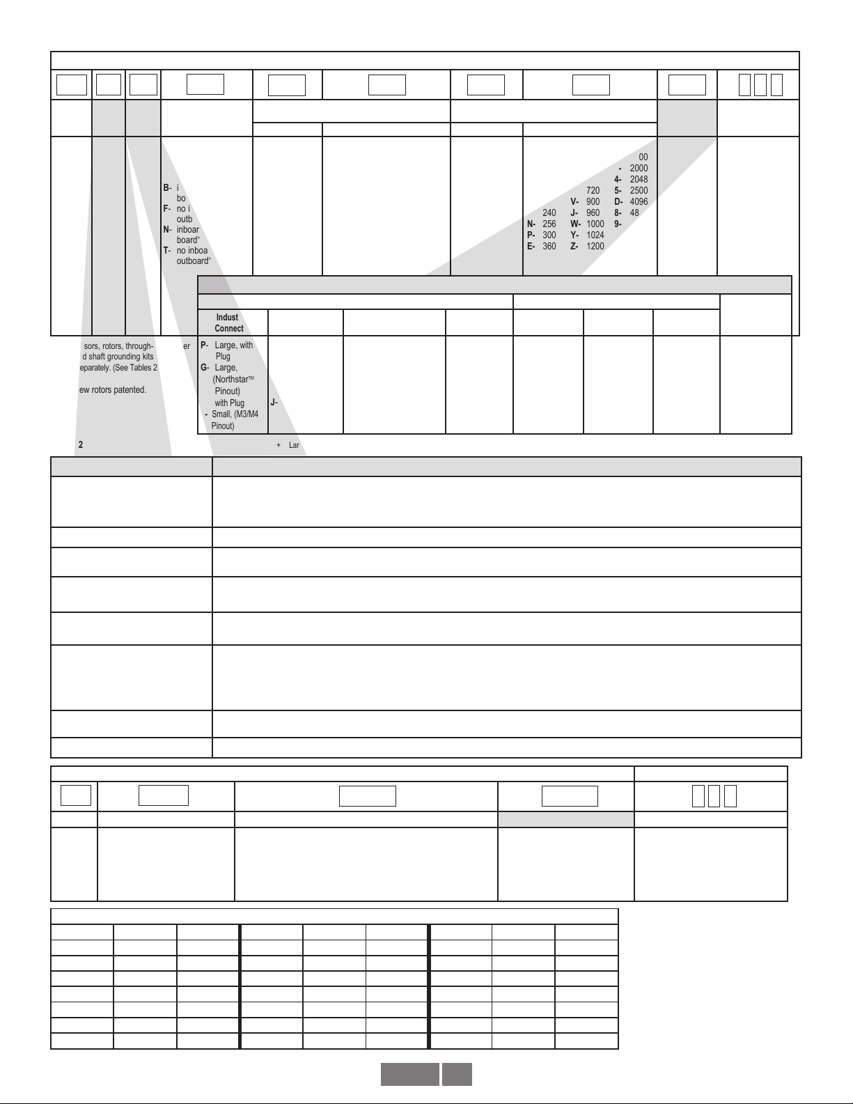
(OPTIONAL) SHAFT GROUNDING KIT INSTALLATION
(Rotors “FA-F9”, “GA-G9”)
Refer to separate Shaft Grounding Kit Instructions (M190-AV850)
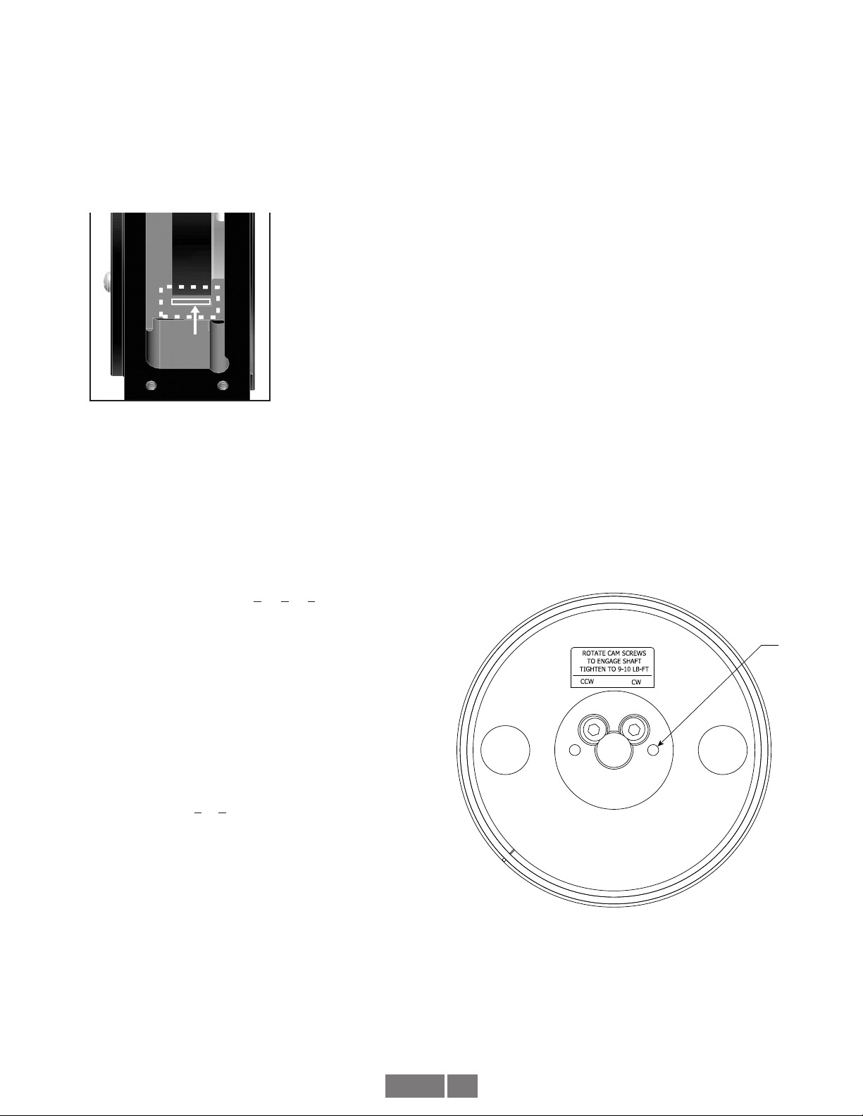
(OPTIONAL) CHECK ROTOR POSITION
1. Remove a sensor or blank side cover plate.
2. Verify the rotor magnetic stripe is aligned with the grooves (see
Figure 5).
3. Replace the sensor or side cover plate.
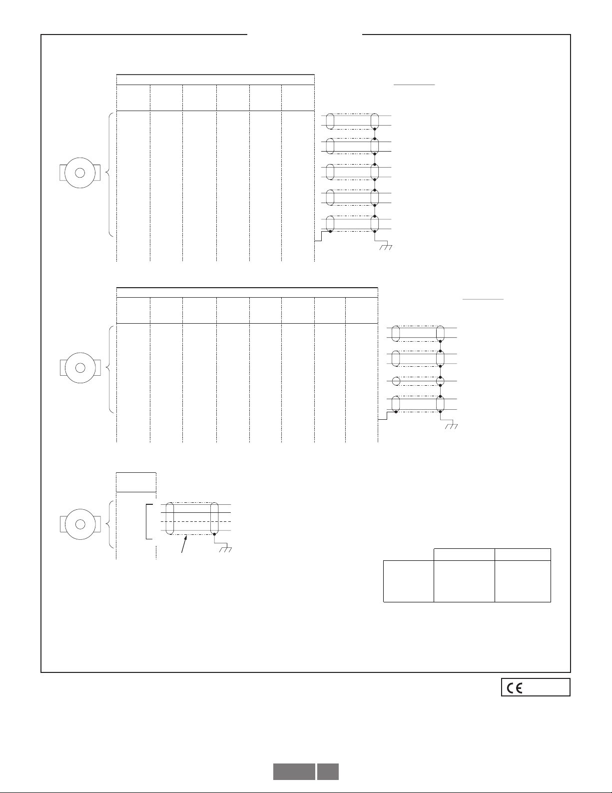
WIRING INSTRUCTIONS
CAUTION
Remove power before wiring.
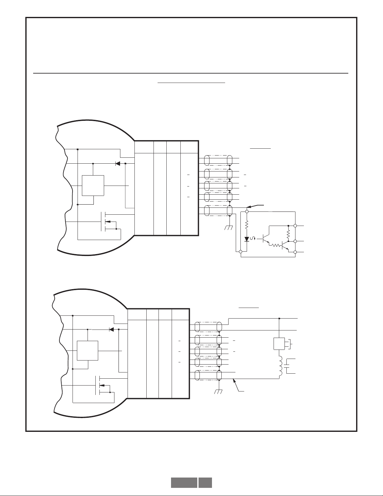
Wiring diagrams are shown in Figure 6 and 7.
For bidirectional operation of the encoder, proper phasing of the two
output channels is important. Phase A channel leads phase B channel
for clockwise shaft rotation as viewed from the anti-drive or accessory
end of the motor (encoder mounting end). Wiring option “G” provides
a pinout compatible with Northstar™ encoders, with a cable shield
connection on pin 10. Note that this option does not ground the shield;
Avtron still recommends grounding the shield at the drive end of the
cable for all wiring options.
CORRECTIVE ACTION FOR PHASE REVERSAL
1) Remove Power.
2) Exchange wires on cable, either at encoder cable end or at
speed controller end (but not both).
a. Single Ended 2 Phase Wiring (see wiring diagram)
Exchange A and B at the use end of the wires.
b. Differential 2 Phase Wiring (see wiring diagram) Exchange
either A with Ain the phase A pair OR B with Bin the
phase B pair but NOT both.
3) Apply power.
4) Verify encoder feedback is correct, using hand rotation of shaft,
or jog mode of the speed controller.
Interconnecting cables specified in the WIRE SELECTION CHART in
Figure 6 are based on typical applications. Refer to the system drawing
for specific cable requirements where applicable.
Physical properties of cable such as abrasion, temperature, tensile
strength, solvents, etc., are dictated by the specific application.
General electrical requirements are: stranded copper, 22 thru 16 gauge
(Industrial EPIC Connector options can use 14-20 AWG), each wire pair
individually shielded with braid or foil with drain wire, 0.05 uF maximum
total mutual or direct capacitance, outer sheath insulator, 1,000 ft.
max. See WIRE SELECTION CHART in Figure 6 for some suggested
cables.
See Figure 7 for examples of alarm output wiring.
NOTE
When using the industrial connector (“1”, “G”, “P”, “Q”,
“V”, “X”, or “Z” options), the minimum wire size is 20 gage,
and 20 gage (only) wire ends must be tinned with solder
before connection at the screw terminals.
MAINTENANCE
GENERAL
This section describes routine maintenance for the Avtron AV850
Encoder. For support, contact field service for Avtron Encoders at
216-642-1230. For emergency after hours service contact us at
216-641-8317. The AV850 SMARTach III circuitry includes a diagnostic
package that includes Adaptive Electronics and a Fault-Check output.
ADAPTIVE ELECTRONICS
A perfect duty cycle consists of a waveform whose “high” and “low”
conditions are of the same duration (50%/50%). The AV850 adaptive
electronics extends the life of the AV850 by constantly monitoring and
correcting duty cycle over time.
FAULT-CHECK
After power-up and the rotor position is checked by the sensor, the
Fault-Check LED will turn GREEN.
If the adaptive electronics reach their adjustment limit for any reason,
the Fault-Check alarm and LED will notify the drive and operator of an
impending failure. The LED will turn RED if the Adaptive Electronics
reach their adjustment limit. This output occurs before an actual
failure, allowing steps to be taken to replace the unit before it causes
unscheduled downtime. Fault-Check annunciation is available as an
“alarm” output through the connector and as an integral LED.
TROUBLESHOOTING:
If the drive indicates a loss of encoder/tach fault and the AV850 fault-
check LED is not illuminated, check the encoder power supply. If power
is present, check polarity; one indicator of reversed power supply is that
all outputs will be high at the same time. If the drive indicates encoder
fault, but the LED shows GREEN, then check the wiring between the
drive and the encoder. If the wiring appears correct and in good shape,
test the wiring by replacing the AV5 sensor module. If the new module
shows GREEN, and the drive still shows encoder loss/tach fault, then
the wiring is faulty and should be repaired or replaced.
If the alarm output and/or LED indicate a fault (RED):
1. Remove a sensor plate or one of the sensors, and use
the built-in gauge to check the location of the rotor (see Figure
2.1). Ensure the label marked “This side out” is facing away
from the motor.

JACK CREW
HOLES M6
AV850 5
2. Remove the AV5 sensor from the housing. Clean the housing
mounting surface for the AV5 sensor and the AV850 housing.
Ensure the AV5 sensor is directly mounted on the AV850
housing, with no sealant, gasketing, or other materials, and
that it is firmly bolted in place.
If the alarm output and/or LED indicate a fault (RED) on a properly
mounted AV5 sensor and the rotor is properly located, replace the AV5
sensor.
An oscilloscope can also be used to verify proper output of the
AV850 encoder at the encoder connector itself and at the drive/
ROTOR ALIGNMENT GROOVE
Figure 2.1
Figure 2.2
Rotor magnetic strip aligns with groove.
controller cabinet. If the outputs show large variations in the signals
at steady speed (jitter or “accordion effect”, see figure 9), check rotor
position. If the rotor position is correct, the motor or shaft may be
highly magnetized. Replace any magnetized material nearby with
non-magnetic material (aluminum, stainless) (shafts, etc). For GE CD
frame motors and similar styles, Avtron offers non-magnetic stub shafts
(included with all “U” style rotor kits). If variations persist, consider
replacing the sensors with super-shielded models, option -004.
If the alarm output and/or LED indicate a wiring fault (ORANGE):
Remove all output wires/connections (A, A, B, B, Z, Z). The LED
should turn GREEN. If the LED does not turn GREEN, the encoder is
not receiving enough voltage at +V to properly operate. Correct input
voltage problem at power supply or cabling.
If the LED turns GREEN once all outputs are disconnected, reconnect
each output, one at a time, monitoring for ORANGE LED. For partial/
resistive short circuits, the LED may take a few minutes to turn
ORANGE. To speed the troubleshooting process, if possible, spin the
encoder while replacing individual output connections. This may make
the ORANGE LED condition occur faster. Once the shorted output(s)
are located, correct the shorting condition, and the encoder LED should
remain GREEN.
If the LED is OFF, but power is being applied to the encoder, check
the output voltage level at A, A,B, B. If all outputs are ON (≈+V), the
connections to +V and COM are reversed. Swap connections between
+V and COM; the LED should turn GREEN.
STATOR HOUSING REMOVAL
To remove the stator housing remove the qty 4 1/2 13 x 3” bolts holding
the housing to the motor.
CAUTION
Take care that the housing does not fall from the pilot and
cause the sensors to crash into the rotor. Damage to the
sensor or rotor could result.
ROTOR REMOVAL
Remove shaft rust and burrs before removing the rotor.
CAM SCREW ROTOR REMOVAL
Disengage the (2) cam screws by turning the left screw clockwise and
the right screw counterclockwise less than 1 full turn. The cam heads
will visibly move away from the shaft. Remove the rotor by hand by
pulling it away from the motor. If the rotor will not move, do NOT use a
gear puller, and do not use a heat gun. Instead, insert two M6 screws,
>25mm length into the Jack Screw Holes shown in Fig 2.2. Alternately
tighten the screws to push the rotor away from the motor and remove it.
LARGE BORE SET SCREW ROTOR REMOVAL
Disengage the (2) set screws by turning the left screw clockwise and
the right screw counterclockwise until removed from the rotor. Retain
the set screws. Remove the rotor by hand by pulling it away from the
motor. If the rotor will not move, do NOT use a gear puller, and do not
use a heat gun. Instead, pry the rotor away from the motor gently, being
careful to only pry against the rotor metal hub and not the magnetic
outer strip.
NOTE
Do not remove the cam screws from the rotor.
RENEWAL AND SPARE PARTS
See Tables 2, 3, and 4.

AV850 6
ELECTRICAL**
A. Operating Power (Vin)
1. Volts........................5-24 VDC
2. Current....................100mA, nominal, no load
B. Output Format
1. 2O/ & Comp ...........A, A
–, B, B
–(differential line driver)
2. Marker ....................1/Rev, Z, Z
–
C. Signal Type .................Incremental, Square Wave, 50 ±10% Duty Cycle.
D. Direction Sensing ........O/ A leads O/ B for CW rotation as viewed from the
.................................. back of the tach looking at the non-drive end of the
motor.
E. Phase Sep...................15% minimum
F. Frequency Range........@5V, @1m cable, 250 kHz Max
................................. @24V, @300m cable, #8 output, 45 kHz Max
G. PPR.............................4-50000***
H. Line Driver Specs........See table
I. Connectors..................See connector options on page 1
J. LED Indicator................GREEN: power on, unit ok.
................................RED: alarm on
................................. ORANGE: wiring fault (Thermal Overload; Under-
................................voltage)
MECHANICAL
A. Rotor Inertia: ...............0.12-0.41 Oz. In. Sec.2
B. Acceleration: ...............5000 RPM/Sec. Max.
C. Speed:.........................6000 RPM Max.****
D. Weight: ........................2-3 lbs [0.9kg to 1.36kg].
E. Sensor to Rotor
Air Gap (nominal):.......0.045” [1.14mm]
Tolerance:....................-0.030”/+0.015” [-0.76mm/+0.38]
F. Rotor Axial Tolerance ..±0.050” [±1.27mm]
ENVIRONMENTAL
Solid cast aluminum stator and rotor
Fully potted electronics, protected against oil and water spray
Use “W” cable option on IP66/67 applications
V-Ring seals provided on through shaft covers
Operating Temperature: ............ -40 to 100°C, 0-100% condensing humidity
Vibration: 18 g’s
Shock: 1 meter drop test
LINE DRIVER OPTIONS
SPECIFICATIONS
* Alarm not available on connector option “G” (NorthstarTM compatible pinout)
** Electrical specifications for SMARTach III model (rev BA or later), consult Nidec
Industrial Solutions for earlier model specifications.
***(PPR) Standard maximum PPR is 5000. Consult Factory with your application
for PPRs up to 50,000.
**** (Speed) Maximum RPM may be limited for PPR > 2,500. Consult Factory with
your application.
LINE DRIVER OPTIONS
Electrical Specifications 6 8 9 Units
Input Voltage 5-24 5-24 5-24 VDC
Nom Output Voltage 5-24 5-24 5 VDC
Line Driver 7272 Hx 7272
Output Resistance Typ
13 75 13 ohms
Maximum Peak Current 1500 800 1500 mA
Maximum Average
Current 120 200 120 mA
Voh Typ VIN-1 VIN-1 VIN-1 VDC
Vol Typ 0.5 0.2 @ 10mA line
current 0.5 VDC
Cable Drive Capacity
1000’ @ 5V
500’ @ 12V
200’ @ 24V
1000’ 1000’ feet
Protection
Reverse
Voltage yes yes yes
Short
Circuit yes yes yes
Transient yes yes yes
Power to A,
Gnd to A/ yes yes yes
Alarm
+V(out) Output voltage equal to input voltage.
Alarm* Open collector, normally off, goes low on alarm,
sink 100mA max, 50VDC max
LED Green=power on, Red=Alarm
Orange=Wiring Error (Thermal Overload; Under-voltage)
Marker One per revolution. Pulse width
approximately 2° (1/128 of a revolution)

AV850 7
PIN OUT
COM
+V
A
A
–
B
B
_
Z
Z
_
+V (OUT)
ALM
BLACK
RED
GREEN
YELLOW
BLUE
GRAY
ORANGE
WHITE
BROWN
VIOLET
OPTION
“N”, “K”,
“W”
“N”, “K”,
“W”
OPTION
“A”, “B”,
“C”, “L”
“A”, “B”,
“C”, “L”
OPTION
“P”, “V”, “Q”,
“X”, “Z”
“P”, “V”, “Q”,
“X”, “Z”
OPTION
“T”
OPTION
“R”, “S”
“R”, “S”
A
B
D
G
E
H
C
I
F
J
1
6
2
7
3
8
4
9
5
10
COMMON
+V
ØA
ØA
–
ØB
ØB
_
MARKER
MARKER COMPLEMENT
RELAY +V REF*
ALARM*
GROUND
(Shield)**
FUNCTION
FOR DIFFERENTIAL APPLICATIONS
F
D
A
H
B
J
C
K
NC
NC
E10NCNCNC
E
1
6
2
7
3
8
4
9
NC*
NC*
OPTION
“G”
(Shield)**
NC 10NCNCNC
+V (Encoder Power)
ØB
ØA
COMMON
MARKER
RELAY +V REF*
ALARM*
GROUND
FUNCTION
FOR SINGLE ENDED APPLICATIONS
PIN OUT
+V
B
A
COM
Z
+V (OUT)
ALM
RED
BLUE
GREEN
BLACK
ORANGE
BROWN
VIOLET
OPTION OPTION OPTION OPTION
“T”
OPTION
B
E
D
A
C
F
J
6
3
2
1
4
5
10
D
B
A
F
C
NC
NC
B
C
E
A
D
NC
NC
OPTION
“E” & “F”
6
3
2
1
4
NC*
NC*
10
E
D
A
F
NC
NC
NC
OPTION
“G”
FOR SINGLE ENDED SINGLE PHASE WIRING APPLICATIONS
RED
ORANGE
GREEN
BLACKA
B
C
D
E
COMMON
+V (Encoder Power)
SIGN
Z (Optional)
AL
GROUND
CABLE BELDEN 8771
OR EQUIVALENT
OPTION**
“H” & “J” **(M727A Replacements)
OPTION
“3”
WIRING DIAGRAMS
TYPICAL WIRE SELECTION CHART
for 18 AWG, multiple pair, individually shielded
2 PAIR 9368 6062
ALPHABELDEN
3 PAIR 9369 6063
9389
9388
6 PAIR
4 PAIR
6066
6064
* See Figure 7 page 6 for examples of alarm output wiring.
** Avtron recommends shield grounding at drive end. Shield pin does not ground the shield.
EU Declaration of Conformity
FIGURE 6
Labeled

AV850 8
BLACK
RED
GREEN
YELLOW
BLUE
GRAY
ORANGE
WHITE
BROWN
VIOLET
OUTPUT OPTIONS
A
B
D
G
E
H
C
I
F
J
9
4
5
10
2
8
3
7
6
1
+V(OUT)
Z
Z
A
B
B
A
+V
COM
Vcc
OUT
COM
300 OHM
MIN.
GND
FUNCTION
ENCODER
ØB
ØA
ØA
ØB
4-16 VDC SOLID STAT E RELAY
LINE
DRIVER
{
FUNCTIONAL DIAGRAM
50 mA MAXIMUM
“N”,“K”,“W”“A”,“B”,
“C”,“L”
“P”,“V”,
“X“,“Z”“T”
ALM
MARKER
MARKER COMPLEMENT
COMMON
+V (Encoder Power)
{
BLACK
RED
GREEN
YELLOW
BLUE
GRAY
ORANGE
WHITE
BROWN
VIOLET
T
OUTPUT OPTIONS
A
B
D
G
E
H
C
I
F
J
9
4
5
10
2
8
3
7
6
1
ALM
+V(OUT)
Z
Z
A
B
B
A
+V
COM
MARKER
MARKER COMPLEMENT
GND
FUNCTION
+V (Encoder Power)
COMMON
24
VDC
RELAY
+
-
POWER
SUPPLY 115 VAC
SINK 100 mA MAXIMUM,
WITHSTAND 50 VMAXIMUM
REFERENCED TO COMMON
ENCODER
FUNCTIONAL DIAGRAM
ØB
ØA
ØA
ØB
LINE
DRIVER
“N”,“K”,“W” “A”,“B”,
“C”,“L”
“P”,“V”,
“X“,“Z”
Example 2. Alarm Output Using Separate 24 VDC Power Supply and Relay.
Applies to all Model AV850 Encoders except connector styles “E”, “F”, “G”, “H”, “J”, “R”, “3”.
ALARM OUTPUT CONNECTION
Avtron SMARTach III encoders provide an alarm signal if maintenance is required under specific circumstances. A green LED indicates power on and proper
operation, red indicates alarm on. Following are application examples provided to help install the alarm output.
Example 1. Alarm output using +V(OUT). +V(OUT) is equal to +V, the encoder power supply.
SMARTach III™
Application Examples
FIGURE 7
Note: Alarm output is “low true” ; i.e. it goes to øV when activated

AV850 9
Imperial
(US) Sizes
Shaft Bore
Inboard Covers
Flat Thru-Shaft
Cover
Magnetic
Shield
Seal ONLY Seal ONLY
-AN
-NA-
-NA-
-NA-
-NA-
-NA-
-NA-
-NA-
-NA-
A35355
A35355
A35355
A35355
A35355
A35355
A35355
A35355
A35355
A35355
A35355
A35355
A35355
A35355
A35355
A35355
A35355
A35355
--AN-8091742-30243A43903BAC-41513BACAT-51903BAT"057.0
4181741-11262A4181741-30243A51513B*BCBT-51903BBT"526.0
-AN--AN-1391743-30243ACC-41513BCC
CT-51903B
CT"578.0
0091742-11262A0091744-30243AEC-41513BECET-51903BET"000.1
3781743-11262A3781745-30243AFC-41513B
FCFT-51903BFT"521.1
4881744-11262A4881747-30243AHC-41513BHCHT-51903BHT"573.1
1091745-11262A1091748-30243AJC-41
513BJCJT-51903BJT"526.1
-AN--AN-20917401-30243AKC-41513BKCKT-51903BKT"057.1
2091746-11262A20917411-30243ALC-41513BLCLT-51903BLT"578.1
6881747-11262A68817421-30243AMC
-
41513BMCMT-51903BMT"000.2
3091748-11262A30917431-30243ANC-41513BNCNT-51903BNT"521.2
40917421-11262A40917451-30243APC-41513BPCPT-51903BPT"573.2
3091748-11262A30917441-30243AQC-41513BQCQT-51903BQT"052.2
5091749-11262A50917461-30243ARC-41513BRC
RT-51903BRT"005.2
-AN--AN-50917452-30243ATC-41513BTCTT-51903BTT"526.2
-AN--AN-70917491-30243AWC-41513BWCWT-51903BWT"052.3
-AN--AN-60917402-30243AYC-41513BYCYT-51903BYT"573.3
-AN--AN-60917412-30243AZC-41513BZCZT-51903BZT"124.3
58817401-11262A58817471-30243A2C-41513B2C2T-51903B2T"578.2
94517411-11262A94517422-30243A3C-41513B3C3T-51903B3T"005.3
-AN--AN-34917432-30243A-AN--AN-4T-51903B4T"578.3
-AN--AN--AN-42
-30243A-AN--AN-6T-51903B6T"005.4
Metric Sizes
-AN--AN-9391746-30243A43903B-AN--AN-mm03
-AN--AN-1091749-30243A-AN--AN-
mm24
-AN--AN-40917451-30243A-AN--AN-
mm06
-AN--AN-70917481-30243A-AN--AN-mm08
-AN--AN-
-AN-
-AN-
709174
055174
81-30243A
62-30243A
-AN--AN-mm08
Outboard Covers
Set Screw
Cam Screw
Rotor PartRotor Part
Rotor
Code
Rotor
Code
Through Shaft Rotors
SPARE THROUGH SHAFT ROTORS AND COVERS
Set Screw
Cam Screw
95mm
70mm
90mm
3.625"
3.750"
4.000"
TD
TG B30915-TG
B30915-T1
T1
B30915-TD
-AN-
-AN- -AN- -AN- -AN- -AN- -AN--AN-
-AN-
-AN--AN- -NA- -NA- -AN- -AN-
-AN-
-AN-
-AN-
-AN- -AN- -AN- -AN- -AN- -AN-
-AN-
-AN-
-AN-
-AN-
-AN-
-AN-
-AN-
-AN-
-AN-
-AN-
-AN-
-AN-
-AN-
-AN-
A35355
B31502-MF
B31502-MJ
B31502-MP
B31502-MY
B31502-MZ
B31502-M3
B31502-M4
B31502-M5
MF
MJ
MP
MY
MZ
M3
M4
M5
Table 4
SPARE END OF SHAFT ROTORS
Motor Specific Style Universal Style
Motor Frame Code Rotor Shaft
Grounding Kit Code Rotor Shaft Adapter** Shaft
Ground Kit Magnetic Shield
Universal rotor only*
(no stub shaft) -NA- -NA- -NA- CB* B31515 none -NA- -NA-
CD 180-32x EF/HF B30916-EF A34137 QF/UF/GF B31515 B31516 A34396 A35355
CD36x EN/HN B30916-EN A34138 QN/UN/GN B31515 B31517 A34397 A35355
CD4xx EP/HP B30916-EP A34139 QP/UP/GP B31515 B31518 A34397 A35355
CD444/CD505E EQ/HQ B30916-EQ -NA- QQ/UQ/GQ B31515 B31631 A34397 A35355
CD43xx, 44xx, 54xx,
64xx, 65xx -NA- -NA- QV/UV/GV B31515 B31676 A34397 A35355
CD45xx, 75xx, 76xx -NA- -NA- QW/UW/GW B31515 B31676 A34397 A35355
CD46xx, 47xx, 85xx, 86xx -NA- -NA- QY/UY/GY B31515 B31677 A34397 A35355
CD68x -NA- -NA- QZ/UZ/GZ B31515 B31678 A34397 A35355
CD5xx (excluding CD505) E2/H2 B30916-E2 A34140 Q2/U2/G2 B31515 B31519 A34397 A35355
E9- CD60xx, 61xx, 62xx,
67xx, 68xx, 69xx E9/H9 B31092 A34141 Q9/U9/G9 B31515 B31520 A34397 -NA-
All except CD505
and CD680 -NA- -NA- -NA- UU B31515
B31516, B31517,
B31518, B31637,
B31676, B31677
-NA- -NA-
** Shaft adapter part numbers for rotor style “Q” (stacked encoders) is the same as above but with a “-1” suffix.
* Note Universal rotor (CB) is a 5/8" thru-shaft cam screw style rotor. Universal style kits (GF-G9, QF-Q9, UF-U9) add the required stub
shaft to fit the rotor to GE CD frame motors.
Table 3

AV850 10
0.19 (4.83)
8.5015
8.5035
DIA
(215.938)
(215.989)
DIA
DRAIN PLUG 1/8 - 27 N.P. T.
NOTE: If the pulse generator will be
exposed to water spray, the bottom
1/8" pipe plug should be removed.
2.54
(64.52)
1.29
(32.8)
0.24
(6.10)
5FT (1524.0) MIN
45∞
0.562 (14.275) DIA - 4 HOLES
EQUALLY SPACED ON A
7.250 (184.150) DIA.
4.38
(111.25)
9.00 (228.60) DIA
LED Indicator
STANDARD:
1/2-14 NPT
COVER PLAT E
SINGLE OUTPUT
ONLY
OPTION “P”, “G”
PLUG-IN INDUSTRIAL CONNECTOR
ALTERNATES SHOWN BELOW
OPTION “N”
FLEXIBLE WATER-
PROOF CONDUIT
RIGHT
MODULE
LEFT
MODULE
0.53 (13.5)
3.83 (97.3) 4.66 (118.4)
OPTION "R"
OPTION "3"
6 PIN MS
CONNECTOR
(M940)
OPTION "K"
2.80 (71.1)
3.06
(11.7)
1.53
(38.9)
OPTION "A"
BULKHEAD CONNECTOR ONLY
OPTION "B"
WITH MATING PLUG & CABLE GROMMET
1.97
(50.0) 3.67 (93.2)
Assembled
0.53
(13.5)
1.66
(42.2)
OPTION "C"
3.25
(82.6)
OPTION "E" & "H"
BULKHEAD CONNECTOR ONLY
OPTION "F" & "J"
WITH MATING PLUG
0.53
(13.5)
1.42
(36.0)
3.08 (78.2)
Assembled
1.85
(47.0)
1.42
(36.0)
OPTION "L"
0.53
(13.5)
2.09
(53.0)
1.97
(50.0)
3.87 (98.3)
OPTION "S" 0.53
(13.5)
36.50 (927.0) MIN
OPTION "W"
0.53
(13.5)
36.50 (927.0) MIN
OPTION "T"
Terminal Block
2.00
(50.8)
4.31
(109.5)
1.16
(29.3)
1.16
(29.3)
0.312 (7.92)
4 Holes
Box is 3.12 (79.25) Deep
0.53
(13.5)
4.750 (120.6)
5.50 (140.0)
5FT (1524.0) MIN
OPTION "X"
SURFACE MOUNT CONNECTOR ONLY
OPTION "Z"
WITH MATING PLUG
0.53
(13.5)
0.41 (10.5)
1.20
(30.5)
4.31
(109.5)
1.574
(40.0)
2.13
(54.0)
3.228 (82.0)
3.70 (94.0)
0.18
(4.5)
0.217 (5.50)
4 Holes
36.50 (927.0) MIN
5.641
(143.3)
5.641
(143.3)
1.072
(27.2)
MOTOR SIDE
OPTION “TA-T9, MA-M9”
SET SCREW STYLE ROTOR
5.641
(143.3)
1.011
(25.7)
MOTOR
SIDE
OPTION
“CA-C9, UA-U9,
GA-G9”
CAM SCREW
STYLE ROTOR
PLUG WITH CONDUIT ADAPTER
OPTION “Q”
REMOTE BASE
FOR BALDOR
TEFC/TENV
MOTORS
18.00
[457.2]
MIN
0.30
[7.6]
0.81
[20.6]
ADDITIONAL CONNECTOR OPTIONS
Dimensions in parenthesis are in millimeters.
All dimensions are approx.
FIGURE 8
FIGURE 9 Excessive Signal Variation (“Jitter”)
VARIATION > ± 15%
PHASE A
PHASE B

AV850 11
SMARTach™ III is a trademark of Nidec Industrial Solutions, Inc.
Features and specifications subject to change without notice.
Avtron Encoder standard warranty applies. All dimensions are in inches (mm).
0.19 (4.83)
8.5015
8.5035
DIA
(215.938)
(215.989)
DIA
DRAIN PLUG 1/8 - 27 N.P. T.
NOTE: If the pulse generator will be
exposed to water spray, the bottom
1/8" pipe plug should be removed.
2.54
(64.52)
1.29
(32.8)
0.24
(6.10)
5FT (1524.0) MIN
45∞
0.562 (14.275) DIA - 4 HOLES
EQUALLY SPACED ON A
7.250 (184.150) DIA.
4.38
(111.25)
9.00 (228.60) DIA
LED Indicator
STANDARD:
1/2-14 NPT
COVER PLAT E
SINGLE OUTPUT
ONLY
OPTION “P”, “G”
PLUG-IN INDUSTRIAL CONNECTOR
ALTERNAT ES SHOWN BELOW
OPTION “N”
FLEXIBLE WATER-
PROOF CONDUIT
OPTION “D
No Inboard, Domed
Outboard Cover Plate
RIGHT
MODULE
LEFT
MODULE
0.53 (13.5)
3.83 (97.3) 4.66 (118.4)
OPTION "K"
2.80 (71.1)
3.06
(11.7)
1.53
(38.9)
OPTION "A"
BULKHEAD CONNECTOR ONLY
OPTION "B"
WITH MATING PLUG & CABLE GROMMET
1.97
(50.0) 3.67 (93.2)
Assembled
0.53
(13.5)
1.66
(42.2)
OPTION "C"
3.25
(82.6)
OPTION "E" & "H"
BULKHEAD CONNECTOR ONLY
OPTION "F" & "J"
WITH MATING PLUG
0.53
(13.5)
1.42
(36.0)
3.08 (78.2)
Assembled
1.85
(47.0)
OPTION "L"
0.53
(13.5)
2.09
(53.0)
1.97
(50.0)
3.87 (98.3)
5.641
(143.3)
5.641
(143.3)
1.072
(27.2)
MOTOR SIDE
OPTION “TA-T9, MA-M9”
SET SCREW STYLE ROTOR
5.641
(143.3)
1.011
(25.7)
MOTOR
SIDE
OPTION
“CA-C9, UA-U9,
GA-G9”
CAM SCREW
STYLE ROTOR
PLUG WITH CONDUIT ADAPTER
(04.45)
(0.68)
(0.063)
OUTLINE DIMENSIONS AND OPTION DETAILS
For additional wiring options see Figure 8.
FIGURE 10
REV: 005
REV DATE: 04/12/2022
Avtron Encoders are the Most Reliable Encoders in the World
Nidec Industrial Solutions
8901 E. Pleasant Valley Road
•
Independence, Ohio 44131-5508
E-mail: [email protected]
•
Web: www.avtronencoders.com
Phone: (216) 642-1230
•
Fax: (216) 642-6037
Table of contents
Other Avtron Media Converter manuals

Avtron
Avtron XR56 SMARTSafe User manual

Avtron
Avtron HS6A User manual

Avtron
Avtron SMARTSafe XR125 User manual

Avtron
Avtron SHAFTach M585 User manual

Avtron
Avtron M3-3 User manual

Avtron
Avtron AV45 Series User manual

Avtron
Avtron AV115 User manual

Avtron
Avtron M6-1 User manual

Avtron
Avtron HS35M User manual

Avtron
Avtron SMARTSafe XR4F User manual

Avtron
Avtron AV85 User manual

Avtron
Avtron XR56 SMARTSafe User manual

Avtron
Avtron HS4 User manual

Avtron
Avtron HS35A User manual

Avtron
Avtron AV6A Series User manual

Avtron
Avtron M6C-4 User manual

Avtron
Avtron SMARTSafe XP5 User manual

Avtron
Avtron AV56A User manual

Avtron
Avtron HS6M User manual

Avtron
Avtron SMARTSafe XR67 User manual