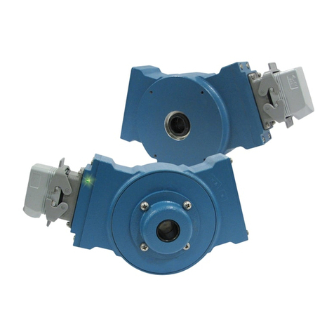
XR67 2
The XR67 construction materials contain less than 6% magnesium
by mass. These materials are not considered as able to trigger
an explosion in normal operating modes in accordance with the
requirements for category 2 or 3 equipment. These materials are
not known to react with any explosive atmospheres to which the
XR67 may be subject. It is however the responsibility of the end
user to ensure that the XR67 is selected correctly for the potentially
explosive atmosphere in which the equipment is to be put into
service.
The XR67 installation is similar to AV67. Installation and removal
videos for the AV56/67/85/115 are available on Avtron’s web site.
Refer to the back page of these instructions for outline and mounting
dimensions. The motor must comply with 1998 NEMA MG 1, section 4,
for tolerances on diameters and runout for shafts and accessory faces.
Axial float or endplay plus rotor location toleration must be less than
±0.050”.
In preparation for installing the Model XR67 encoder, it is first
necessary to clean both the accessory motor shaft and the mounting
face. These surfaces must be inspected and any paint, burrs, or other
surface imperfections removed.
Installation procedures should be performed only by qualified
personnel. Safety precautions must be taken to ensure machinery
cannot rotate and all sources of power are removed during
installation.
ROTOR INSTALLATION
The motor shaft must project at least 0.88” from the motor recessed
pilot. For set screw rotors only: Apply anti-seize compound to the
motor shaft. For all rotors: Slide the rotor onto the shaft with the
marking “Motor side” facing in, (toward the motor face). The rotor
centerline must match the sensor centerline. To accomplish this, use
the rotor locating gauge (A28504) and slide the rotor onto the shaft
until it is in the proper position as shown in Figure 1. If a guage is
not available, use the stator housing alignment grooves as shown in
Figure 3.
STANDARD CAM SCREW ROTOR INSTALLATION
Turn the cam screws of the rotor in the directions shown on the rotor
to engage the cams. Tighten to 50-60 in-lb [5.6 - 6.8 N-m] (See Figure
2) using the 3mm hex wrench. Total cam screw rotation will be less
than one turn.
CAUTION
Do not adjust the cam screws before motor shaft
mounting; bottoming out the screws, or backing them
out excessively, can lead to insufficient shaft holding
force. Thread locker is preapplied on the cam screws.
LARGE BORE SET SCREW ROTOR INSTALLATION
Apply thread locker to the rotor set screw holes, preferably from the
inside of the rotor bore before mounting. Tighten the rotor set screws
to 15 in-lb [2 N-m] using the 2mm T-handle hex wrench.
CAUTION
Use only a T-handle or torque hex wrench to tighten set
screws; using a right angle wrench will not provide
enough holding force, and the rotor may slip.
STATOR HOUSING INSTALLATION
The stator housing is attached to the motor using four socket head
cap screws (4) 3/8”-16 x 1”, locating on a 5.88” bolt circle. Longer
bolts (not included), are required for sandwich installation between a
motor and a brake. Install the four mounting bolts using thread locker
and torque to approximately 20-30 ft lbs [27 to 40 N-m] using the
5/16” T-handle hex wrench.
VERIFY ROTOR LOCATION
To ensure the rotor is properly located on the shaft: remove the back
cover if factory-preinstalled, and verify that the outer face of the rotor
is at the same depth as the alignment grooves, using a straight edge
tool. (Figure 3)
CAUTION
Do not use silicone sealants or caulk of any kind on
the motor or encoder face; these can cause
misalignment or sensor scraping damage. The XR67
electronics are fully sealed; water may enter and leave
the rotor area as needed. A drain hole option is available
if frequent moisture buildup is expected.
COVER INSTALLATION
Covers must not interfere with the motor shaft or rotor. The longest
shaft that can be used without interfering is 0.95” [25.1mm] with a
standard flat cover (Cover Style option “F”) and 2.80” [71.0mm] with
an extended “pie pan” cover (Cover Style option “E”). Through shaft
covers with seals are available for other applications (Cover Style
option “T”).
EXTENDED COVER MOUNT (Cover Style option “E”)
The extended cover mounts to the encoder housing using quantity 4
#6-32 x 0.31” screws, lock washers, and thread locker.
THRU SHAFT AND FLAT COVER INSTALLATION
(Cover Style option “T” and “F”)
The housing has a machined step in the outboard face to accept the
cover and a recessed groove for the retaining ring. Insert the cover,
line up ears on cover, smooth side facing out, fully into the machined
step until it seats against shoulder. Using a spiral assembly method,
install the retaining ring by first inserting the squared off end into the
machined groove. Flex the ring and insert it into the groove walking
it around the perimeter (A flat blade screwdriver can be used). Final
position should have the ring fully seated into groove. Remove the
cover by reversing above procedure, starting with the tang end.
V-RING INSTALLATION FOR THRU SHAFT COVERS
(Cover Style option “T”)
For thru shaft covers, verify that the shaft passes completely through
the hole in the cover. Apply a small amount of silicone lubricant to
the cover plate around the thru shaft hole. The V-Ring seal should
compress axially when it is pressed against the clean, smooth face
of the cover plate. See Figure 4 for proper installation and V-Ring
compression.
WIRING
CAUTION
Be sure to remove power before wiring the encoder.
Be sure to ground the cable shield: Avtron recommends
grounding the shield at the isolator module for Zone 1
applications or in the drive cabinet for Zone 2
applications. Cable should not be grounded multiple
places. An intrinsic safety ground is required at the
XRB1 Isolator Module.
CAUTION
SMARTSafe encoders include a local ground lug for
customer convenience and encoder frame grounding if
required to meet local electric code requirements or site
operator protection standards. This is NOT the required
XRB1 intrinsic safety ground connection required for
hazard protection against ignition of explosive
atmospheres!
Wiring diagrams are shown in the following pages.
CAUTION
Zone 1 and Zone 21 applications utilize the XRB1
isolator which requires an intrinsic safety ground to
provide hazard protection. Failure to connect this
ground, or providing an inadequate safety ground path
could result in an spark/ignition hazard which can
result in property damage, injury, or even death.
