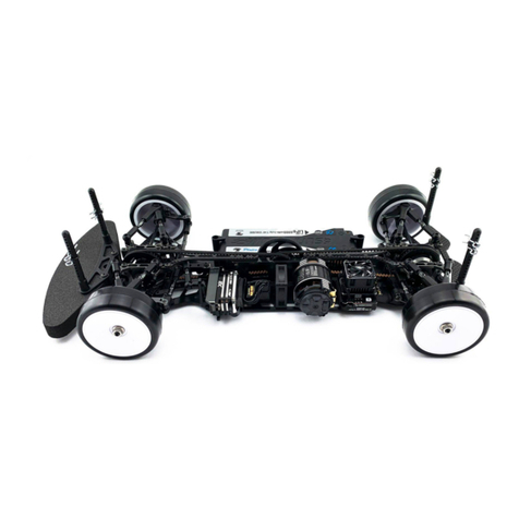
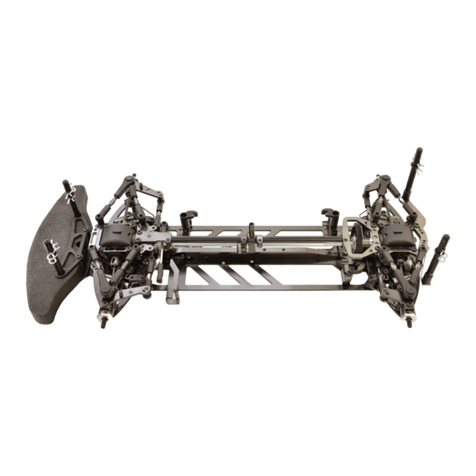
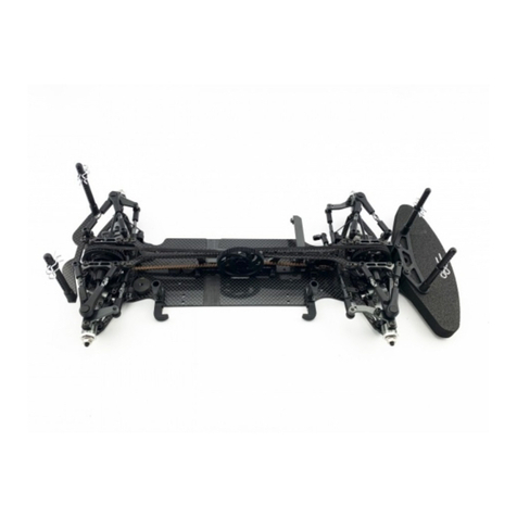
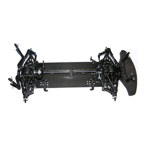
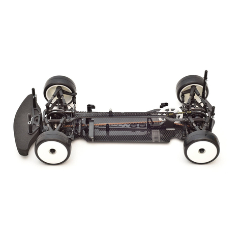
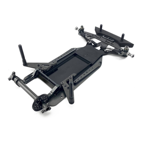
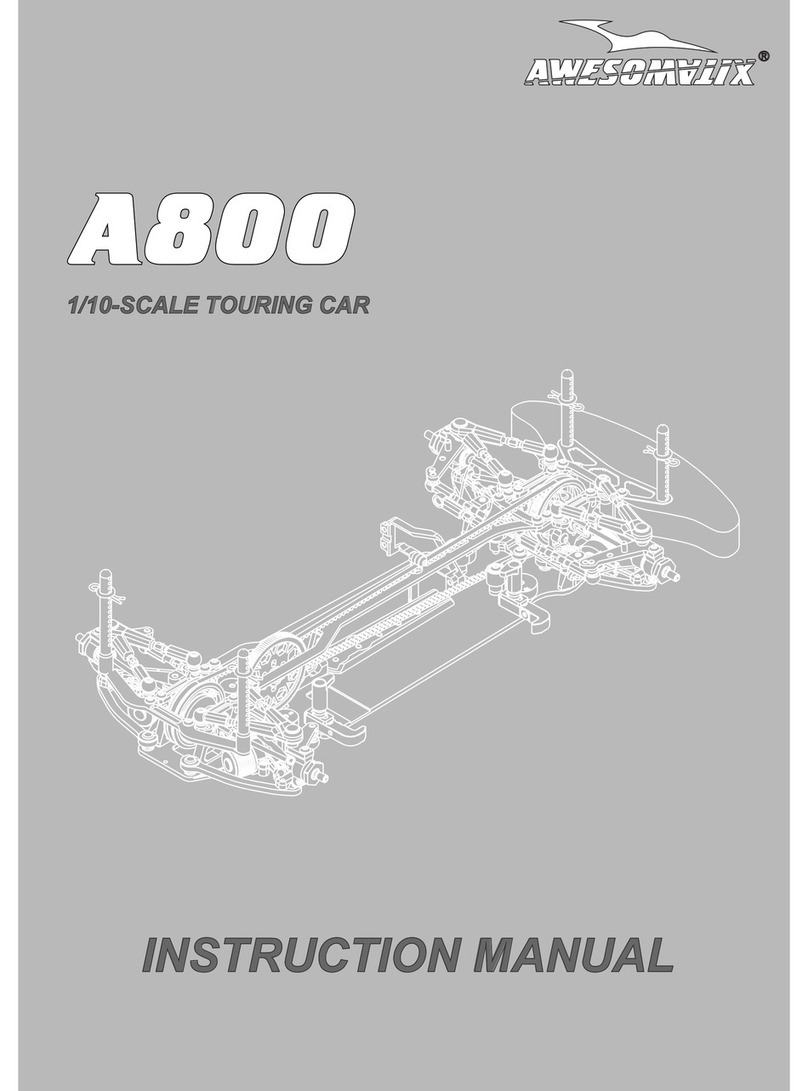
Awesomatix A800R User manual

A800R
1/10-SCALE TOURING CAR
INSTRUCTION MANUAL

2
BEFOREYOUSTART
The
A800Rcar is
the high-quality,innovative1/10-scale touring car and should bebuilt only bypersons with previous
experience building R/C model racing cars.
This is not atoy and is not intended for use bychildren without direct supervision of a responsible, knowledgeable adult.
Read the instruction manual carefully and fully understand it before beginning assembly. If you have any problems
or questions please do not
hesitate to contact the Awesomatix team at support@awesomatix.com. If,for any reason,
you decide that you do not want your
A800Rcar
you must not begin assembly.
Your
A800R car
cannot be returned to UAB “Awesomatix” for a refund or exchange if it has been fully or partially
assembled.
This kit is a radio controlled model racing product and could cause harm and personal injury.
The
A800Rcar
isdesigned for use on r/c car race tracks. It should not be used in general public areas.
UAB “Awesomatix”acceptsno responsibility for any injuries caused by making or using this kit.
Due to policy of continuous product development the exact specifications of the kit may vary.
UAB “Awesomatix”do reserve all rights to change any specifications without prior notice. All rights reserved.
INTRODUCTION
Congratulations on purchasing your Awesomatix car!
The A800Rcar was produced by UAB “Awesomatix” company.
The A800Rcar utilises many unique features, including some patented innovations.
GENERALPRECAUTIONS
•Many of the items in this kit are small enough to be accidentally swallowed and are therefore potential choking hazards, making them potentially fatal.
Please ensure that when assembling the kit you do so out of the reach of small/young children.
•Take care when building, as some parts may have sharp edges.
•Please read this manual carefully to understand which ancillary items (tools, electrics, electronics etc) are used with this kit.
UAB “Awesomatix”acceptsno responsibility for the operation of any such ancillary items.
Exercise care when using tools and sharp instruments.
•Follow the operating instructions for the radio equipment at all times.
•
•Never touch rotating parts of the car as this may cause injury.
Keepthewheelsofthemodeloffthegroundwhencheckingtheoperation of the radio equipment.
•To prevent any serious personal injury and/or damage to property, be responsible when operating all remote controlled models.
•The model car is not intended for use on roads or areas where its operation can conflict with or disrupt pedestrian or vehicular traffic.
•
•Do not run your car in poor light or if it goes out of sight. Any impairment to your vision may result in damage to your car or, worse, injury to others
or their property.
•As a radio controlled device, your car is subject to radio interference from things beyond your control. Any such interference may cause a loss of
control of your car so please consider this possibility at all times.
When not using RC model, always disconnect and remove battery.
•Insulate any exposed electrical wiring to prevent dangerous short circuits.
•Take maximum care in wiring, connecting and insulating cables. Make sure cables are always connected securely.
Check connectors for if they become loose and if so reconnect them securely. Never use R/C models with damaged wires.
A damaged wire is extremely dangerous and can cause short-circuits resulting in fire.
ASSEMBLYNOTES
Before starting each build-stage check that you have the right quantity and size of items for the build-stage. To assist you with
the assembly of your
A800Rcar
we have included full-size images of all the small hardware parts laid out so that you can
place items on top of the images to check are they correct size/length. You can find the useful tips and pictures of
A800Rassembling on the internet site: http://site.petitrc.com/reglages/awesomatix/SetupSheetsAwesomatixA800R.html
EQUIPMENT RECOMMENDED(NOT INCLUDED)
Radio Transmitter
•Radio Receiver
•Electronic Speed Control
•Steering Servo
•Servo Horn
•
•Electric Motor
Pinion Gear (64 or 48 Pitch)
•
Spur Gear (64 or 48 Pitch)
•7.4 VLi-Po Battery
•
• 190mm Body Shell
Touring Car Wheels, Tires,Inserts
•
TOOLS RECOMMENDED(NOT INCLUDED)
1.5mm, 2.0mm Hex Driver
•
•5.5mm, 3/8, 10mm Wrenches
• Callipers
Hobby Knife
•Camber Gauge
•Ride Height Gauge
•
Thread Lock
•
5’000 cst Diff Silicone Oil
•
400 cst,500 cst Silicone Shock Oil
•
• Joint Grease
•O-Ring Grease
3
Note these items at assembling of the car.
3 mm
4 mm
SS3X5
5 mm
6 mm
8 mm
8 mm
2,5
5 mm
6 mm
SB3X6
SB3X8
8 mm
10 mm
12 mm
8 mm
SF3X8
6 mm
SF3X6
5 mm
4 mm
1,5
7,8 mm
5,8 mm
1,5
5,6 mm
3,7 0,5 mm
6 mm
0,5 mm
6 mm
1 mm
6 mm
1,75 mm
8 mm
0,1 mm
1,5 mm
8 mm
1,9 mm
7,5 mm
1 mm
4 mm
SS3X3
SS3X4
SC2X6
SC2X8
SB25X8
SB3X5
SB3X10
SB3X12
SF3X5
SC2X4
PIN01
PIN02
P16
SH0.5 (silver)
SH1.0 (gray)
SH1.75 (black)
SH0.1
OR06
OR05V
OR2010V
5,9 mm
Note the shoulder
4,25 mm
5 mm
9 mm
4,1 mm
5,8 mm
ST112
screws - used for fastening only
bulkheads and dampers to the lower deck!
3,5 mm
2 mm
2,3 mm
7,25 mm
2,2 mm
19 mm
ST143
with
OR1010V
o-ring
6,9 mm
4
ST69-0
4,1 mm
5,2 mm
4
ST019
3 mm
10 mm
7 mm
6 mm
4 mm
8 mm
ST122
OR52V
SPR23
P46R ball
P68
AT247
AT119
SPR07
B106RS
ball bearing
B85
ball bearing
B73SS
ball bearing
B63SS
ball bearing
B415
ball bearing

4
STEP1-Assembling ofthe D3Dampers
ST143
#1Insert OR2010Vo-ring into the upper cavity of AM242R/Lcase.
Lubricate ST143with small amount ofthe silicon oil. Note that one OR1010Vo-ring isalready factory installed on each ST143.
Hold OR2010Vo-ring with forefinger and insert the lubricated ST143into AM242R/Lhole.
Rotate and press on ST143simultaneously with 1,5mm hex screwdriver so that the pointed tip of ST143should pass through
OR2010Vo-ring.
OR2010V
P45
At proper installation OR2010Vo-ring
must occupy the top groove of ST143.
OR1010V
OIL
#3Put OR1705V - the thin 17x0,5mm o-ring into the slot of AM240 cover. Try don’t twist this o-ring at installation into slot.
#2Turn ST143 valve into position for further installation of the AT241 rotor.
OR1705V
AM240
#4Choose the desirable orientation of AT243plate before installation - for linear damping mode or for progressive damping mode.
Insert AT243plate into AM242case fully. The fit of the AT243can be a bit tight.
Linear damping mode is recommended for carpet tracks. Progressive damping mode is recommended for asphalt tracks.
AT243AT243
Hole position for linear damping mode Hole position for progressive damping mode
Note:As a starting point werecommend400cst silicone oil for the front dampersand 500 cst silicone oil for the rear dampers.

5
#7Prepare the damper’s stand for using with the Tamiya style RC Damper Oil Air Remover tool.
Screw P67stand to three P14-2posts (cutted till ~43mm length) or to the air remover’s original stand instead one of plates.
#5Lubricate the outer edge of the P63 piston with small amount of the “O-ring Grease”. MXLRbrand o-ring grease is recommended.
Don’t allow the grease or any other lubricant to get on the P63 piston leg! Insert P63 piston into AT241 on full depth.
Insert AT247probe into the output hole of AT241rotor and shift P63piston to the recommended ~7mm position.
Add a bit of “O-ring Grease”
on this edge of P63
P263membrane can be used instead of P63piston.
Deform P263till ~ 4,2 mm size like on the picture and install into AT241.
Use AM240 cover as a guage for P263positioning in AT241.
“O-ring Grease” is not needed.
AT241
AM240
P263deformed P263
P263
push in
P67
SB3X6 x3
P14-2 x3
P67
SB3X6 x2
AT241
AT247P63
Don’t allow the grease
or any other lubricant
to get on the P63 piston leg!
P63
#6Put OR52V o-ring on AT241 rotor’s shaft and add the silicone oil into the gap under o-ring to fill this gap fully.
Insert AT241 rotor into AM242body onfull depth.
OR52V
AT241
OIL
AT241
AM242R
AM242L
TIP /Recommendation to use
MAX-02-003 - MXLR Awesomatix A800R ShockVac
MAX-01-003 - MXLR O-Ring grease (for P63 & OR52V)

6
#8Install thedampersontheairremover standandkeep them vertically.
Add thedesirable siliconoilinto thedamper’sinner space. Theoillevel should reachthetop face of AT243onthis stage. Don’t
forget to fill by oil thecavity over P63pistonor over P263 membrane. Check the narrow slot behind AT243 and add the oil
also there. It’s not easy to detect the lack of oil in the slot behind AT243so please pay more attention to this.
#9Vacuum should be applied at least 10 times x 2 minutes. Try to reach the maximum possible level of vacuum on every cycle.
There are a lot of small cavities inside dampers that hold air for a long time. The air bubbles remain to go out even after several
cycles of “vacuum is on” - “vacuum is off ”. So please pay maximum attention on the air bubbles removing process.
AM240 with OR1705V
Oilshould fill this slot fully
#10Add more oil into damper. The oil level should be a little over the upper edge of AM242. Use long M3 screw in the special hole
of AM240for holding. AM240cover should be inserted 100% horizontally and slowly to allow the oil to fill the cavity of AM240
and to oust the air through two through holesof AM240. AM240should dive into oil under its weight on this stage.
Next press on AM240with finger slowly and submerge AM240cover full wayinto the pocket of AM242body.
Oillevel
M3screw
OIL
#11Keep the damper verticallyon table and screw two ST122 screws. Please don’t overtighten screws to avoid the thread stripping!
Wipe excess oil off the damper body with paper towels and remove M3screw.
ST122 x2

7
#12Install ST102F(longer part)on the front dampers and ST102R(shorter part)on the rear dampers.
Keep the damper vertically and swing AT241rotor few times in both directions. In case you feel the air bubbles inside the damper
remove AM240 cover, add the oil into the damper and repeat the AM240 installation process.
SC2X6
#13Install AT119, SPR23, P46R, ST69-0and note orientation of SPR23 by the round end directed to the damper shaft.
ST69-0
AT119
SPR23(note orientation!)
#14Install SPR01 springs (for A800Rkits) or SPR01S springs (for A800RAkits).
ST102R
ST102F
SC2X8
ST102R
ST102F
Note the hole
Comment:Note that dampers are used in the carin horizontal position. So the possible small airbubbles are located nearto the top
wall of the damperand don’t affect on the rotoraction. So these dampers are equallyeffective on track even with a bit of the airbubbles
inside. You can feel the airbubbles onlywhen you place dampers verticallyand airbubbles can go through the rotor blade edge.
P46R
P46R
SPR01 SPR01S (note “S”laser engraving)
Optional ST69-15andST69-25screwsfor 15% and 25%
spring’s action progression areavailable (not included).
P46Rball shouldbe placedbetween
SC2X6screwand ST69-00screw.
2.0 mm for front dampers, 3.6 mm for rear dampersInitial settings
Use DG1Xgauge
ST102F
ST102R
27,5 mm
29,5 mm
Note the hole

8
AT21ST-Ax4
STEP2
STEP3
REAR
SF3X6x4
or
SF3X8 x4
FRONT
SH1.0x4
P03x4
P03x4
STEP4
Combinations of SH0.5, SH1.0and SH1.75 spacers under AT21ST-Aballs are used
for adjusting of the car’s roll center.
Use SF3X8 screws when install more than 1,5mm of spacers under AT21ST-A balls.
Note: Don’t fully tighten screws under AT21ST-A balls at this stage.
Note:C01B-RCCarbon Lower Deck is used in A800Rkit.
C01B-RAAlloy Lower Deck is used in A800RAkit.
SH0.5x4
AT21ST-Ax4
SH1.0x4
SF3X6x4
or
SF3X8 x4
Snap P03ball cups gentlyon AT21ST-Aballs.
Tip!
Drill 3 mm hole in P03 cups for convenient
tightening of AT21ST-A balls with already
installed P03cups via 2mm hex driver.
Drill gently in
this direction
ST112 x4
ST112 x4
Reardamper
Reardamper Frontdamper Frontdamper
Note: Use ST112centering screws for dampers mounting.
REARFRONT

9
STEP5
STEP6
STEP7
SF3X8
P12X
SF3X8
SF3X8
SF3X8
P12X
P12X
P12X
SS3X4x2
or
SS3X5 x2
SF3X5 screws can be added or removed from the motor mount to alter
overall flex, as well as change the flex distribution along the chassis.
54 321
Motor mount screws designation for setup sheet.
FRONTREAR
SS3X4x2
or
SS3X5 x2SF3X5
Note:SS3X5 set screws should be used if
more than 2 mm spacers are used under AT21ST-Aballs.
Snap C204Rand C204Llower arms on P03 cups.
Note orientation of recesses on the arms!
Note:C204Rand C204Llower arms should
swing down free under its weight.
Crimp P03cups with flat lips pliers
if the lower armsmovement is not free.

10
STEP8
STEP9
STEP10
P07
Crimp P03cups with flat lips pliers
if the lower armsmovement is tight.
P07
Prepare 2sets with this layout
ST205
SB25X8 x2
ST205
P04
P04
Prepare 2sets with this layout
Install ST205with P04on all four suspension arms.
snap
snap
ST205
P04
OR14V
Optional OR14Vrubber o-rings can be used instead of P07 clips.
Snap P07clips and tighten
SB3X6screwsunder AT21ST-Aballs after.

11
STEP11
STEP12
Install two ST24ball studs on
the rear AM278bulkheads.
ST112 x4
B106RS
AT120-5
DT22
AT62-5M
Note:AT120XB is fullyfactory
assembledforyourkit.
Attention!Note orientation of
this chamfer on DT22.
AT120XB
B84RS
AT120XB
SB25X8
ST24x2
ST112 x4
AM278 x2
Note: Use ST112centering screws for AM278bulkheads mounting.
AM278 x2

12
STEP13 STEP14
Fill with desirable silicone oil (not included).
Screw
AT123Bcase with 10mm wrench slowly.
The excessive oil will go out through the ST31-1axial hole.
STEP15STEP16
AT124B
OR13V
B106RS
G07
P39
AT123B
G08
G07
G07
G07
ST31-1
B85
OR05V
P46R
ST23X
B106RS
PIN02
oil level
OR06
PIN02
WA03
G08
WA02
WA02
WA02
WA02
P46R
ST23X
OR06
B85
OR05V
P138-1
SC2X4x3
OR13
OR05M
Thread Lock
Attention!
Don’t overtighten
SC2X4 screws.
Such overtigh
t
ening
deforms P138 Pulley.
Use the Thread Lock
for these screws.
D
iff Oil
WA03
ST31-1
Note the initial position
ofP46Rpiston in this
ST31-1axle.
B106RS
P46R
TIP /Recommendation to use
MAX-01-003 - MXLR O-Ring grease (for OR05V)
MAX-02-002 - MXLR Awesomatix TC Multi Tool
TIP /Recommendation to use
MAX-01-001 - MXLR Ball Bearing oil

13
B106RS
ST37X
ST37X
B106RS
AT03BX
STEP17
SF3X8
SF3X8
SB3X5x3
P138S-1
Thread Lock
STEP18
P110
P110P110
P110
Attention!
Don’t overtighten SC3X5 screws.
Such overtigh
t
ening deforms P138
S
Pulley.
Use the Thread Lock for these screws.
Note the correct orientation
of AT03B
X
Axle
regarding
to P138
S
Pulley.
TIP /Recommendation to use
MAX-01-001 - MXLR Ball Bearing oil

14
AM19-Rx2
BEL351B
BEL351B
AM19-Rx2
SB3X5x4
STEP19
SB3X5x4
Note:Thisrecess on AM19-R
should be oriented downward.
front belt
rear belt
Note this correct layout of of belts, diff and spool!
Initialposition of rear P110
Initialposition of frontP110
Note this
pin position
Note this
pin position

15
STEP20
STEP21
STEP22
ST59
B73SS
Install P05on all four suspension arms.
B73SS
SH0.5
SH1.0
ST59
snap
P05
Use bigger hole for
SWB-R-1.2and
SWB-R-1.3
sway bars.
Use smaller hole for
SWB-R-1.0 and
SWB-R-1.1
sway bars.
AT142
SWB-R-1.2
Note:SWB-R-1.3-three strips
SWB-R-1.2- two strips
SWB-R-1.1- one strip
SWB-R-1.0 - nostrips
AT142
SS3X3
SS3X3
B63SS
Note:Don’t tighten SS3X3set screws onthis stage.
B63SS
Install rear and front sway bars into P12X.
Adjust AT142stoppers disposal to reach the centered position
of sway bars andtighten SS3X3set screws after that.
Attention!
Thedeflected tips of sway bar
should bedirected downwards.
Cutoff this legof P12X
whenusing more than3mm
spacers underAT21ST-A
balls.

16
STEP23
STEP24
STEP25
SF3X5 x2
ST118L-1
SH0.5
SH1.0
AM24-20
SB3X6Attention!Servo horn neutral position.
Note:
Recommended
length of the servo
horn 16,5-17,5 mm.
Servo horn(not included)
SB3X6x2
SB3X12
SB3X6
SH0.5
SB3X5AL
AM180EVO
SB3X10
AT21ST-A x2ST24
Use SB3X5AL screwasa steering
limiter (usually on carpet tracks).
AM180EVObellcrankposition canbe
changed via shifting of ST118L-1 axle
within 1mm range for adjusting of
the Ackermann setting.
We recommend the rearward position for carpet and the forward
position ofAM180EVObellcrank for asphalt tracks.
SF3X5x2
ST118L-1
SH0.5
SH0.5x2
AT21ST-A
SH1.75x3
Servo(not included)
Optional BSSX steering
system is possible to
install with optional
AM24-8servo holder and
AT52Aposts.
Awesomatix A700L/A701L
servo is possible to install
with optional AM152stand.
SF3X10x2
AM24-8AT52Ax2
SB3X5x2
BSSXset
SH1.75x4
SH1.0x2
AM152
TIP /Recommendation to use
MAX-09-001 - MXLR Adjustable Servo Arm 23T
MAX-09-002 - MXLR Adjustable Servo Arm 25T

17
STEP27
STEP28
SB3X5
ST24x4
SB3X5x4
ST019 x2FRONT
REAR
A
B
C
D
E
F
Top decks
holes designation
for setup sheet.
ST019screws layout in
different holes of both
top decks is used for
independent adjusting
the torsional flex on
each end of the car.
C127
C127S
SB3X5x4
ST019 x2
Note the orientation of recesses
on the C127/C127Stop decks.
recess
ST019
SB3X5
Note:C127topdecksare used in A800Rkit.
C127Stop decks are used in A800RAkit.
C127
C127S
ST24x4
SH0.5 x4
SH1.0 x4
FRONT
REAR
STEP26
C45F
C45F
SB3X5
SB3X5
C45R
C45R
These bridges
can be cut on
both top decks
for increasing of
the torsional flex.

Assemblefront right and
front left steering knuckles.
Assemblerear right and
rear left steering knuckles.
18
SB3X5
AM06WL
AM14LS
ST03
SH1.0
STEP29
AM06WL
SB3X5
ST03
ST24
AM23-R
ST03
Note:Other combinations of SH0.5,SH1.0and SH1.75 spacers canbeinstalledunder
ST03andST24 ball studsto set-up the car for different track condition.
SH1.0
AT21ST-A
Note the difference between
ST03and ST24Ball Studs!
ST03
ST24
SH1.75
ST24
ST03
SH0.5
SB3X6
SH1.0
SH1.0
SH1.0
Front leftsteering knuckleRear right steering knuckle

19
Prepare two front drives.
STEP30
PIN01
PIN01
PIN01
SPR07
ST01
ST16
ST16
ST17-1
ST113
Apply Joint Grease to
the rubbing surfaces.
B415
B415
ST38
ST38
Attention!
Note the mutualorientation of ST16at
screwing of ST38.
The pins of bothST16should be parallel
to each other.The recommended wrench
for screwing of ST38is 3/8USstandard
wrench (~9,53 mm).
SPR07
Thread Lock
ST116
Front drives for US-spec kits.
ST17-1US
ST01
PIN01
PIN01
ST16
Version ofthefront drivefor US-speckits.
ST16
ST38US
ST113
ST38US
Thread Lock
Attention!
ApplyJointGrease on the rubbing surfaces of
ST113, ST16, ST17-1US, ST01, PIN01.
Applyabitof the Thread Lock on ST17-1US
thread. Tighten ST38USnuts byfingers.
TIP /Recommendation to use
MAX-01-002 - MXLR Driveshaft & Gears oil
MAX-02-002 - MXLR Awesomatix TC Multi Tool

20
Prepare two rear drives.
Tip:
Use a 2.5mm flat screwdriver
to unclamp ST02rear axle.
ST116
SPR07
PIN01
ST02
ST16
ST114
B415
B415
Apply Joint Grease to
the rubbing surfaces.
PIN01
Thread Lock
SPR07
Assembling/disassembling method
1. Unclamp ST02rear axle a bit.
2. Take out/insert ST16u-joint cross
from/into unclamped ST02rear axle.
STEP31
Table of contents
Other Awesomatix Motorized Toy Car manuals

Awesomatix
Awesomatix A800FX User manual

Awesomatix
Awesomatix A800X User manual

Awesomatix
Awesomatix A700 Evo II User manual

Awesomatix
Awesomatix A800 User manual

Awesomatix
Awesomatix A800 User manual

Awesomatix
Awesomatix A12 User manual

Awesomatix
Awesomatix A700 Evo II User manual

Awesomatix
Awesomatix A700L2 User manual

Awesomatix
Awesomatix A800MMX User manual

Awesomatix
Awesomatix A800FX Evo User manual