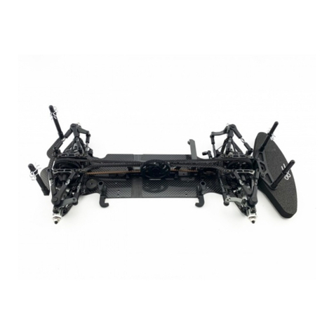
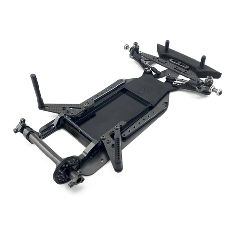
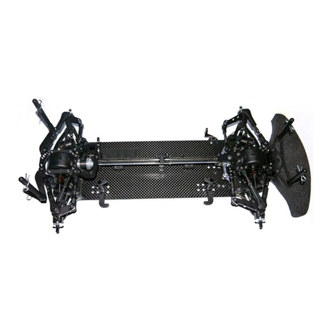
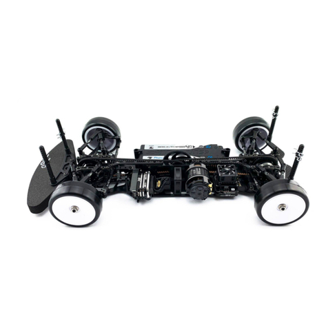
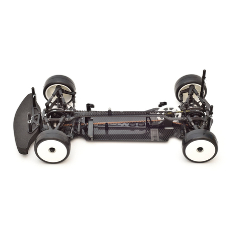
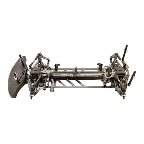
Awesomatix A12 User manual

INCION MANAL
A12
1/12-SCALE ELECTRIC ON-ROAD CAR

2
BEFORE YOU START
T
A12 is
the -q, vv /2- n-road b b b vx
bR/C
T b v b,kb
R b b b I v b
q Ax @x I, ,
A12
bb
Y
A12
bUAB Axxchan bb
This kit is a radio controlled model racing product and could cause harm and personal injury.
The
A12
is designed for use on r/c car race tracks. It should not be used in general public areas.
UAB Awesomatix accept no responsibility for any injuries caused by making or using this kit.
velopment the exact specifications of the kit may vary.
UAB Awesomatix do reserve all rights to change any specifications without prior notice. All rights reserved.
INTRODUCTION
CAwesomatix !
TA12 asbUAB Axc
GENERAL PRECAUTIONS
• Many of the items in this kit are small enough to be accidentally swallowed and are therefore potential choking hazards, making them potentially fatal.
Please ensure that when assembling the kit you do so out of the reach of small/young children.
• Take care when building, as some parts may have sharp edges.
• Please read this manual carefully to understand which ancillary items (tools, electrics, electronics etc) are used with this kit.
Awesomatix Innovations accept no responsibility for the operation of any such ancillary items.
Exercise care when using tools and sharp instruments.
•
Follow the operating instructions for the radio equipment at all times.
•
• Never touch rotating parts of the car as this may cause injury.
Keep the wheels of the model off the ground when checking the operation of the radio equipment.
•
To prevent any serious personal injury and/or damage to property, be responsible when operating all remote controlled models.
•
The model car is not intended for use on roads or areas where its operation can conflict with or disrupt pedestrian or vehicular traffic.
•
• Do not run your car in poor light or if it goes out of sight. Any impairment to your vision may result in damage to your car or, worse, injury to others
or their property.
• As a radio controlled device, your car is subject to radio interference from things beyond your control. Any such interference may cause a loss of
control of your car so please consider this possibility at all times.
When not using RC model, always disconnect and remove battery.
•
Insulate any exposed electrical wiring to prevent dangerous short circuits.
•
Take maximum care in wiring, connecting and insulating cables. Make sure cables are always connected securely.
Check connectors for if they become loose and if so reconnect them securely. Never use R/C models with damaged wires.
A damaged wire is extremely dangerous and can cause short-circuits resulting in fire.
ASSEMBLY NOTES
You can find the useful tips of A12assembling and the A12 editable setup sheet on the Internet site:
http://site.petitrc.com/reglages/awesomatix/setupa12/
EQUIPMENT RECOMMENDED NOT INCLUDED
Radio Transmitter
•
Radio Receiver
•
Electronic Speed Control
•
Steering Servo
•
• Servo Saver
• Electric Motor
Pinion Gear (64 or 48 Pitch)
•
Spur Gear (64 or 48 Pitch)
•
1S Li-Po Battery
•
• 1/12 scale Body Shell
1/12 scale Wheels and Tires
•
TOOLS RECOMMENDED NOT INCLUDED
1.5mm, 2.0mm, 2.5mm Hex Drivers
•
• 12mm Wrench
• Sewing Needle or Sharp Pin
• Callipers
Hobby Knife
•
Ride Height Gauge
•
• Thin CA Glue
Thread Lock
•
• Double Side Tape
• Silicone Oil for Dampers
Joint Grease
•
3
SH1.5W
SF3X10
AM1206
STEP 1
Note: SH1.5W is 7.4x3x1.5mm alloy spacer.
C1204
C1205
SF3X10
SH1.5W
STEP 2
SB3X5AL x2
AM1203
SB3X5AL x2
Note:
SB3X5AL is 3x5mm alloy screw.

4
AM1205
STEP 3
AM1205
SF3X6
SF3X6
AM1204
STEP 4
SS3X4
OR125
OR125
SH1.5W
ST1205
ST1205
ST1209M
ST1209L
Note: SS3X4 set screw tips should just
slightly touchAM1204 chassis surface.
ST1205OR125 (5x1.2mm o-ring)
Rear ball joint Front ball joint
SH1.5W
ST1209L
ST1205
ST1209L
OR125 (5x1.2mm o-ring)
Note: Add small amount of a joint grease
between ST1205 and ST1209M/L.
Use blue s thread lock for SS3X4 screw!

5
STEP 5
STEP 7
STEP 6
Note: Add a bit of into groove of ST1202.
OR153V (
ST1202
OR153V
NoteOR153V
Stretch OR153V and put it on ST1202
!
Note: Add 0,3 g of 50 000100 000 cst silicone oil
into cavity of ST1204 damper case. We recommend
10 000 cst silicone oil as the base setup
Keep ST1204 upright for several
minutes until all oil reaches
the bottom of the cavity.
ST1204
Note: Insert ST1202 damper rotor into ST1204 damper case slowly.
After the lower face of the ST1202 reaches the oil in the bottom of the cavity, the
ST1202 will need an additional force to be pushed fully into the proper position. We
recommend using a rubber band or OR230 o-ring as shown in the picture. The oil will
start to come up towards the top of the cavity of the ST1204 as the ST1202 is pushed
further into that cavity by the o-ring. When the OR153V o-ring and the ST1204 damper
are close to flush (almost fully inserted), please use a sewing needed or a sharp pin
along the recess of the ST1202 to move the o-ring out of position and allow more oil to
be pushed out from the ST1204 case. Using this needle or pin will allow the ST1202 to
be fully seated and sit perfectly flush with the ST1204 damper case.
ST1204
ST1202
OR230
or
rubber band
needle/pin
recess
on ST1202
M3 screws
Note: It is very important to assemble
the damper without any air inside!
The silicone oil has to occupy the gap
between the dampers rotor and case
fully. It can take some practice.

STEP 9
6
STEP 8
Repeat the STEPS 5,6,7 for other side of ST1204 and check that both ST1202 rotors reached the desirable position
(flush with the ST1204 face)
Note: These faces of ST1204
and ST1202 should coincide.
SB3X5
SB3X5
SS3X10
Note:SS3X10
SS3X10turing
blue

7
STEP 10
STEP 11
ST1201
ST1201
ST1201 3mm Ball Stud
ST1203
SF3X6 x2
SF3X5 x2
AM1202
AM1207
Note: ST1201 ball tuds should be
placed into slots of ST1202 rotors.

8
STEP 12
STEP 13
AT1203
SS3X5
SS3X5
SB3X12
SB3X12
SH0.25...SH1.0
SH0.25
SH0.5
SH1.0
SH1.75
SH0.25
SH0.5
SH1.0
SH1.75
SH0.25...SH1.75
B168ZZ
OR15
Stretch OR15 1x5mm o-ring
and put it on B168ZZ ball bearing
Prepare two B168ZZ bearings with OR15 o-rings.
Note: Assortment of SH shims is used for
setting of the desired rear ride height.
Press both B168ZZ bearings into AT1203 rear beam.
Use blue thread lock for SS3X5 screws!

9
STEP 14
Note: ST1208 steering block posts provide 4 deg caster.
Optional ST1208-C5 posts provide 5 deg caster.
AT1206
AT1206
ST1208
1,5mm hex driver
or optional
RHG 4.2 probe
SB3X5
SB3X5
SB3X6
SB3X6
1,5mm hex driver
or optional
RHG 4.2 probe
The tip of 1,5mm hex driver or optional
RHG 4.2 probe is used for alignment of
the appropriate holes of ST1208
and C1205.
ST1208
Alignment of the appropriate holes of ST1208 and C1205 for camber settings.
0.75 deg camber 1.0 deg camber
1.25 deg camber 1.5 deg camber 1.75 deg camber

10
STEP 16
STEP 15
DT1202
T1201
ST24
T1204
SH1.0
SH0.1 x0..2
OR155SI x 0..1
DT1202
T1201
SH0.1 x 0...2
ST1207
Note orientation!
longer part of ST1207
shorter part of ST1207Note orientation of DT1202
SB3X5
SH12S-0.2 x1..7
SH12S-0.2 x1..7
SB3X5
SPR12FS
SPR12FS
SH12S-0.2 x0..6
SH12S-0.2 x0..6
Note orientation of DT1202
Top SH12S-0.2 shims
Bottom SH12S0.2 shims
Note: SPR12FS Front Soft Springs (Silver) and SPR12FM Front Medium Springs (Gold) come in the A12 kit.
SH12S-0.2 0.2mm thickness shims are used to set the
front spring preload and the front ride height.
he front damping of the steering blocks
i :
Number of the (0,1 or 2)
SH0.1 6x8x0.1mmshims
Oil filled steering blocks also
need to a space for exessive
oil to be removed,to bleed
the steering block. Like the
rear damper, use aneedle
to create a gap between the
o-ring and the steering block
to allow excess oil to be
removed.
T
with different oils or
greases.
OR155SI x 0..1
OR155SI
y
SH0.
Another option is to use no orings
and only thick grease on the
ST1207 in the steering blocks,
depending on track conditions.
ST1207
Attention! When installing SH12S0.2 shims,make
sure they surround the ST1207but not below or
above ST1207 end.

11
STEP 17
STEP 18
STEP 19
ST24-4.0 x2
SB3X5AL
Servosaver (not included!)
C1201
SB3X5AL
SANWA SRG servo (not included!)
Servosaver (not included!)
Mini servo (not included!)
Up to 35x30x15mm mini
servos can be installed.
ST24-4.0 x2
SB3X5AL
C1201
SB3X5AL
AT1202
AT1202
SH1.0
SH1.0
SB3X6
SB3X6
SH0.25
SH0.25
Installation of the SANWA SRG servo.
Installation of the standard mini servo.
Installation of the SANWA SRG servo.Installation of the 15mm thick mini servo.
SB3X5
SB3X5
SB3X8
SB3X8
SH1.0
SH1.0
SH1.0
SH1.0
SH0.5
SH0.5
P13-4 P1213
AT25-2
P13-4
P1213
AT25-2
Install both steering links.
Left steering linkRight steering link
Note: ST24-4.0 are 4.0mm ball studs. ST24-4.0 fit P1213 4.0mm ball cups.
Note: P1213 4.0mm ball cups are used for the inner steering joints.

12
STEP 20
STEP 21
P06-1
ST1211
C1203
P06-1
Note: Press P06-1 collars into C1203 from lower face
of C1203 and apply a drop of CA glue to set them.
CA glue (not included)
Rear body holders assembling.
SPR12S0.5
Initial position of the side spring.
ST1211 spring retainer should
be screwed fully.
Snap the spring on the groove of ST1211
retainer and rotate the spring to find the mutual
angular position that provides a perfect
alignment of the spring and retainer.
Assemble the left body holder in the same manner as the
right body holder and install both body holders on the
chassis.
SB3X10 x4
SH4.0 (6x3x4mm spacer) x4
Note: Additional spacers can be used together with SH4.0to
change the side springs operational range.
Using the outer hole for ST1211 retainer
provides about a 50% increase in the
effective spring rate against side roll.
Use this hole for the side spring as the base setting.

13
STEP 22
STEP 23
SB3X10
SB3X10
SF3X10
SF3X10
P14-2
P14-2
P14-2
P14-2
P1215
Note: Use thin double
sided tape to secure
P1215 foam bumper on
C1204 bumper plate.
SH0.25
SH0.25
SB3X10 SB3X8
Motor (not included)
AT1215 OR91 or OR915
Note: Use OR91 9x1mm o-ring with the thick
spur gears. Use OR915 9x1.5mm o-ring with
the thinner spur gears (TC-style spur gears).
Note: Tighten AT1215 nut via12mm wrench.
Please dont overtighten AT1215 nut!
STA1212
Spur gear (not included)
AT1215
with
OR91 or
OR915

14
STEP 24
Note: The second SC25X8 M2.5x8 screw is used for
perfect axial balancing of the left wheel hub.
SC25X8
SC25X8
AT1207
SH12R0.5
SH12R0.5
C1206
Note: Optional ST1212 steel axle can be used
instead of C1206 carbon axle.
SC25X8
AT1208
SB3X6
SB3X5AL x2
Spur gear (not included)
SB3X5AL x2
SB3X6
Note: Two SB3X5AL M3x5 alloy screw with one SB3X6 M3x6 steel
screw are used for perfect axial balancing of the right wheel hub.
SH12R2.0
SH12R3.5
SH12R2.0
Note: The second SC25X8 M2.5x8 screw is used
for perfect axle balancing of the left wheel hub.
SH12R3.5
Note: The set of SH12R*** spacers shown ensures
correct initial centering of the rear axle.
Carbon Spool set CS-1 (optional).

15
STEP 25
STEP 27
STEP 26
B156
B156
SB3X5
SC3X5 x3
or
SC3X6 x3
SH12F0.5
Pinion gear
(not included)
Insall:
peed conroller (no inclded),
Receier (no inclded),
Bae ( icded),
Transponder ( icded).
Front 1/12 wheel
(not included)
Rear 1/12 wheel
(not included)
Note: Combination of SH12F0.5 spacers
on both sides of the front wheel is used
for the front width adjustment.
Note: Use SC3X5 or SC3X6 depending of the rear rims chosen.
Some rims may need optional 3x8 mm screws (not included).

16
RHG 4.2 Ride Height Gauge (optional)
ST1215 RHG Spacer
ST1214 RHG Probe
AT1210 RHG Indicator
+1RHG Spacer position for ride height
measuring within 4.0 - 5.mm range.
+1,5RHG Spacer position for ride height
measuring within 4.5 - 5.7mm range.
RHG 4.2 gauge is designed for sand measuring the ride height under rear damper of the
A12 car DRH - Damper Ride Height)and can be also used for s and measuring of the front
ride height (FRH) and the rear ride height (RRH).
RHG 4.2 gauge provides a 3.0 - 4.2mm range for ride height measuring without ST1215 spacer.
With ST1215 spacer the gauge provides a 4.0 - 5.2mm and 4.5 - 5.7mm ranges (positions +1
and +1.5 of ST1215 spacer).
The DRH - ride height under rear damper measuring.
The RRH - rear ride height measuring.The FRH - front ride height measuring.

17
Setting of the DRH - the ride height under rear damper.
The ride height under rear damper (DRH is set via preload of two side coil springs SPR12S in
conunction with the o additional preload via set screws in two side beams AM1205.
These beams act as springs when the screws in them press on the AM1204 chassis plate.
A12 setup sheet includes two values for the rear ride height.DRH 1shows the ride height resulting
from side spring pressure only, without the use of AM1205side beams. DRHride height is the final
ride height of the car (which can be a combination of both side springs and side bars to reach this final
desired height). DRH1
DRH
Setting of the Rear Droop.
AM1205
AM1204
SS3X10Droop Screw Depth)
Rear Droop.
Droop Screw Depth or via
counting of the number of turns the screw is screwed into
d
,4 full turns of SS3X10 screw
amper
corresponds to Droop Screw Depth.
Droop Screw Depth value intohe
A12 editable setup sheeto
d
DRH RRH
Droop Screw Depth
SS3X10
ST1204damper case

NAME
COUNTRY
RACE
TRACK
DATE AIR /TRACK
/
TRACK CONDITION
TRACTION
TIRES
ADDITIVE TIME
MOTOR
SERVO BERY
SPUR PINIONROLLOUT
STEER.TRAVEL INOUT
BODY
/RWEIGDIRIBUION %
RECEIVER
ESC RADIO
ESC SETTING
BEST LAPTIME QUALIF./FINAL POSITION /
SETUP SHEET
TOTAL WEIGHT g
A12
FRONT REAR
BRAND
TYPE
DIAMETER
SERVOSAVER
RCKWID
FRONT mm
RER mm
RIDEEIG
RON(R)
UNDERDMER(DR1)mm
UNDERDMER(DR)mm
RER(RR)mm
FRONDROOP mm
RER DROO mm
SERVO POSITION LEFT RIG
BATTERY PLUGSFRONT BCK
ESC POSITION ERIG
mm mm
STEERING HUB POST
ST1208
ST1208-C5
OER
SUSPENSION PLATE
C1205
C1205-ZT
C1205AL
C1205AL-ZT
OER
REAR AXLE
SSS SPOO
C-1OO
CARBON
TEE
BADI
LOSE
MEDIUM
TIGHT
TOE OUT °
D D CAE
ECHCA IED FA
ED HGH
AHAL
FOMBUMER
P1215
OER
GERDI
BRND
OI
g
g
g g
DAMPER OIL
SERVOE
C1201
C101-Z
AM105
YE
NO
BODY HOLDER SHIMS mm
WEEBE
OR
ONG
BUMPSTEER IMmm
STEERING BOCK
AT1204
A104-Z
OER
RIDE HEIGHT SPACER mm
SIDEBEM
CREW
SIDERING
SPR12S-C0.5
SPR12S-C0.4
OER
FRONT HUB SETUP
SPRINGSPR12FSSPR12FM SPR12FH
TO SHIMS mm pcs
BOOM SHIMS mm pcs
O-RING TYPE
GREASE
UID
O-RING0pcs1pcspcs
CAMBER
0.75 deg
1.00 deg
1.25 deg
1.50 deg
1.75 deg
OER
FRONT
TIME
mm
1.20
3.6
3.6
1
1
0.00
2

19
Parts # Description Parts # Description
AM1202 Motor Mount SPR12S0.5 Side Spring C0.5
AM1203 Battery Plate SPR05 Body Clip
AM1204 Chassis Plate B156 3/16x5/16x1/8 Flanged Bearing
AM1205 Side Beam B168 1/4x3/8x1/8 Flanged Bearing
AM1206 Front Nut SH12S-0.2 Spring Shim 0.2mm
AM1207 Left Bulkhead SH12F0.5 Front Axle Spacer 0.5mm
AT1201 Steering Block Nut SH12R0.5 Rear Axle Spacer 0.5mm
AT1202 Servo Post SH1.5W 7.4x3x1.5mm Spacer
AT1203 Rear Beam SH12R2.0 Rear Axle Spacer 2.0mm
AT1204 Steering Block SH12R3.5 Rear Axle Spacer 3.5mm
AT1206 Servo Plate Post SH0.1 6x8x0.1mm Shim
AT1207 Left Hub SH0.25 6x3x0.25mm Spacer
AT1215 Spur Nut SH0.5 6x3x0.5mm Spacer (Silver)
AT25-2 Turnbuckle 39mm x 2 SH1.0 6x3x1.0mm Spacer (Gray)
DT1202 Steering Washer SH4.0 6x3x4.0mm Spacer
ST1201 3mm Ball Stud OR155SI 1.5x5mm O-Ring Silicone
ST1202 Damper Rotor OR230 2x30mm O-Ring
ST1203 Downstop Rod OR15 1x5mm O-Ring
ST1204 Damper Case OR125 1.2x5mm O-Ring
ST1205 Ball Cup OR153V 1.5x3mm O-Ring Viton
ST1207 Steering BlockTube OR91 9x1mm O-Ring
ST1208 Steering Block Post OR915 9x1.5mm O-Ring
ST1209-M Ball Stud SC25X8 M2.5x8 Cap Head Screw
ST1209-L Ball Stud Long SS3X4 M3x4 Set Screw
ST1211 Spring Retainer SS3X5 M3x5 Set Screw
ST24-4.0 4.0mm Ball Stud SS3X10 M3x10 Set Screw
ST24 4.8x6mm Ball Stud SC3X5 M3x5 Cap Head Screw
STA1212 Composite Axle SC3X6 M3x6 Cap Head Screw
P1215 Foam Bumper SB3X5 M3x5 Button Head Screw
P13-4 Ball Cup SB3X6 M3x6 Button Head Screw
P1213 Ball Cup 4.0 mm SB3X8 M3x8 Button Head Screw
P06-1 Insert SB3X10 M3x10 Button Head Screw
P14-2 Body post SB3X12 M3x12 Button Head Screw
C1201 Servo Plate SF3X5 M3x5 Flat Head Screw
C1203 Body Holder SF3X6 M3x6 Flat Head Screw
C1204 Bumper Plate SF3X10 M3x10 Flat Head Screw
C1205 Suspension Plate SB3X5AL M3x5 Alloy Screw
SPR12FS Front Spring Soft STS-A12 A12 Stickers Sheet
SPR12FM Front Spring Medium SIO100K 100k silicone oil
Parts # Description
RHG 4.2 Ride Height Gauge
CS-1 Carbon Spool set
AT1204-ZT Steering Block Zero Trail
AT1208 Right Hub
ST1208-C5 Steering Hub Post 5 Deg
ST1208-C6 Steering Hub Post 6 Deg
ST1216 Balance Weight 5 g
ST1212 Spring Steel Axle
C1205-ZT Suspension Plate Zero Trail
C1201-ZT Servo Plate Zero Trail
C1206 Carbon Axle
C1205AL Suspension Plate Alloy
OR155PU 1.5x3mm O-Ring PU
SPR12FH Front Spring Hard
SPR12S0.4 Side Spring C0.4
SH12R5.5 Rear Axle Spacer 5.5mm
SC25X7AL 2.5x7 Cap Head Screw Alloy
Optional parts
Spare parts

WWW.AWESOMATIX.COM
UA AWESOMATIX
Email: [email protected]
All rights reserved. Copyright UA Awesomatix 2020.
Other manuals for A12
1
Table of contents
Other Awesomatix Motorized Toy Car manuals

Awesomatix
Awesomatix A800MMX User manual

Awesomatix
Awesomatix A800FX Evo User manual

Awesomatix
Awesomatix A12 User manual

Awesomatix
Awesomatix A800 User manual

Awesomatix
Awesomatix A700L2 User manual

Awesomatix
Awesomatix A800X EVO User manual

Awesomatix
Awesomatix A800 User manual

Awesomatix
Awesomatix A700 Evo II User manual

Awesomatix
Awesomatix A800X User manual

Awesomatix
Awesomatix A800R User manual