Axia ECR Series User manual

Part No. 35012
FISCHBEIN PORTABLE
BAG
CLOSER
SERIES ECR
OPERATING INSTRUCTIONS
FISCHBEIN COMPANY
DIVISION
OF
AXIA
INCORPORATED
151
WALKER ROAD
STATESVILLE,
N.C
. 28677, U.S.A.
(704) 871-1159
U.
S.A.
and Foreign Pats. Other Pats Pending
•
Printed in U.S.A.

TABLE OF CONTENTS
TABLE OF CONTENTS ............................................................................................. 1
• OPERATION .............................................................................................................. 2
Procedure ....................................................................................................2
Closing a bag...............................................................................................3
Recommendations .......................................................................................3
Threading.....................................................................................................4
MAINTENANCE ..............................................................................................................5
Lubrication ...................................................................................................5
Cleaning.......................................................................................................5
Needle replacement..................................................................................... 7
Looper replacement.................................................................................... 7
Looper stroke adjustment ............................................................................8
Needle bar adjustment.................................................................................9
Looper clearance adjustment.......................................................................9
Length adjustment ....................................................................................... 1O
Feed
dog
height adjustment ........................................................................ 1O
Motor instructions ....................................................................................... 10
ILLUSTRATIONS ....................................................................................................... 12
Housing, needle lever, presser foot .............................................................
12
Main shaft & looper assembly...................................................................... 14
Handle & electric drive ................................................................................. 16
Motor ........................................................................................................... 18
OPTIONAL EQUIPMENT
ECR-12V -12VDC motor.............................................................................. 23
ER
-Air motor ..............................................................................................
25
EH
-Handle and drive..................................................................................
27
ECR-1
-Tape attachment.............................................................................
29
Horizontal stitcher .......................................................................................30
1
From the library of Superior Sewing Machine & Supply LLC - www.supsew.com

SUGGESTIONS
To insure successful operation of machine, study following instructions with care.
Machine
is
shipped with sample of sewing. Check sample for stitching and chain appearance.
After studying instructions, practice sewing on the sample or an empty bag until control of machine
is
mas-
tered. Then proceed
to
close filled bags.
SERVICE
Contact Fischbein Co. for the location of your authorized Fischb-
ein representative for prompt service, thread, oil, and parts sup-
plies.
2
SAFETY
INSTRUCTIONS
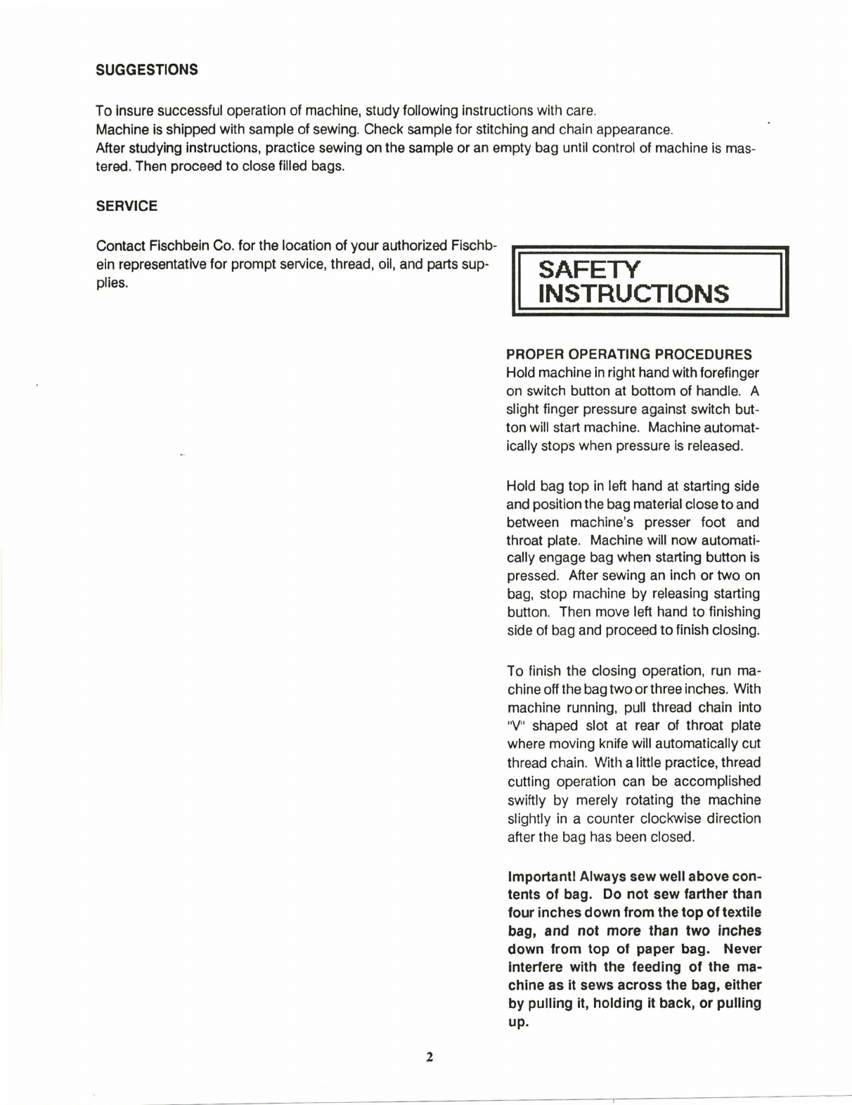
PROPER OPERATING PROCEDURES
Hold machine
in
right hand withforefinger
on switch button at bottom of handle. A
slight finger pressure against switch but-
ton will start machine. Machine automat-
ically stops when pressure
is
released.
Hold bag top
in
left hand
at
starting side
and position the bag material close toand
between machine's presser foot and
throat plate. Machine will now automati-
cally engage bag when starting button
is
pressed. After sewing an inch or
two
on
bag, stop machine by releasing starting
button. Then move left hand
to
finishing
side of bag and proceed
to
finish closing.
To finish the closing operation, run
ma
-
chine offthe bagtwoorthree inches. With
machine running, pull thread chain into
"V"
shaped slot at rear of throat plate
where moving knife will automatically cut
thread chain. With a little practice, thread
cutting operation can be accomplished
swiftly by merely rotating the machine
slightly
in
a counter clockwise direction
after the bag has been closed.
Important! Always sew well above con-
tents of bag. Do not sew farther than
four inches down from the top of textile
bag, and not more than two Inches
down from top of paper bag. Never
interfere with the feeding of the ma-
chine as
it
sews across the bag, either
by pulling it, holding
it
back, or pulling
up.
From the library of Superior Sewing Machine & Supply LLC - www.supsew.com

HOW TO CLOSE A PAPER
BAG
Figure No. 1 Flguro No. 2 Figure No. 3
After bag is filled, weighed, and ready for closing, the operator should first reform gussets. see
FIG
. NO.
1.
Next, fold or "break" top of bag sharply over contents. see
FIG
. NO.
2.
Bring
top
of bag upright into closing position. The sides will be close together, smooth and wrinkle free. See
FIG
. NO.
3.
Proceed with sewing operation, but sewing no more than two inches down from top of bag.
If sifting is a problem, merely tuck
in
the inner ply tightly over contents and proceed to sew remaining plies.
NOTE: Sufficient top
is
necessary to properly "break" bag.
When closing bags that are thick seamed on both sides
such as Calcutta or Sisal bags, pull the seam on the starting
side of bag
two
or
three inches
to
one side, so that you start
closing on the bag proper and not on the seam. See Fig. No. 4.
SAFETY
INSTRUCTIONS
GENERAL
RECOMMENDATIONS
START HERE
l
Figure No. 4
The machine uses a number
12,
4-ply thread, wound on 8-oz. cones For maximum strength be sure and use only
Fischbein Premium Synthetic Thread. Each cone will close about
450
normal size
50
lb. bags.
Installation of any kind
is
not necessary. Merely arrange a box, shelf or bracket so that, between bags operator can
conveniently set machine down or suspend it from the ceiling with a Fischbein Model 1550 suspension unit.
II
AWARNINGII
Do not operate machine on voltages other than specified for the machine.
Machine feeds automatically. Don't pull or hold it back as it feeds across the bag.
Don't try to operate machine with bent or blunt needle.
Don't disturb connecting rod and eccentric, part No. 11079,
or
looper cam, part No. 11310. They are timed and
set.
at factory.
3
From the library of Superior Sewing Machine & Supply LLC - www.supsew.com

THREADING AND TENSION
To install new cone of thread, push thread clamping bolt, part No. 11804, through hole
in
top
of cone and securely lock
in
position with wing nut, part No. 11805. Cone of thread must not rotate
or
wobble on thread stand. Follow illustration
above, being sure that thread passes between the two tension discs, parts No. 11114. Thread needle from outside
to
in-
side of machine. Leave about 1 1/2" of thread dangling through needle, and proceed to sew bags
in
normal manner.
If asphalt laminated or water proof bags are being used, it is necessary to lubricate thread by soaking full cones
in
container
of
Fischbein
Thread
Lubricant.
Tension
is
the degree of resistance the thread meets
in
passing between the tension discs, part No. 11114. Too loose a
tension will cause the thread to tear
or
will leave loose loops of thread on the bag instead of nice firm stitches. Too tight a
tension will also cause the thread to tear or will cause textile bag material to pucker. In either case, the machine may not
chain off. To alter the amount of tension, loosen upper tension nut, part No. 11116. Turn lower tension nut, part No.
11117
, about 1/8 turn at a time -up to loosen tension,
or
down to tighten tension -testing on material -until desired stitch
appearance
is
obtained.
Be
sure to
re
-lock upper tension nut.
4
From the library of Superior Sewing Machine & Supply LLC - www.supsew.com

FISCHBEIN SEWING HEAD
SERIES ECR
MAINTENANCE INSTRUCTIONS AND ADJUSTMENTS
II
AWARNING
II
ALWAYS UNPLUG THE MACHINE
BEFORE DOING MAINTENANCE,
PARTS REPLACEMENT OR AD-
JUSTMENTS.
MAINTENANCE NOTE:
Genuine Fischbein Cleaning Lubricant and #5-100 Lubricating Oil are
available from any Authorized Representative.
Oiling (Figure 1):
This machine
is
equipped with a MANUAL OILING SYSTEM. The OIL RESER-
VOIR
and the OIL PUMP are found at the cord-end of the HANDLE.
Oil Reservoir: Use Fischbein #5-100 Lubricating Oil. The OIL RESERVOIR and
PUMP must have a supply of clean oil at all times.
The oil level can be viewed through the clear end of the reservoir.
CAUTION:
Never operate this machine with the oil reservoir cap removed.
To lubricate the moving parts: Press the BUTTON on the OIL PUMP two times.
This will dispense the correct amount of oil for an average four hours use under
normal conditions.
Cleaning (Figure
2:
To clean the dirt from the machine:
1. Unthread the machine.
2. With the machine running, dip the portion shown in about
four inches (100mm) of lubricant for about 1
Oseconds.
3. Use a brush to clean the back of the machine.
II
AWARNING
II
Use Fischbein Cleaning Lubricant.
Do NOT use gasoline or similar agents.
5
(FIGURE
1)
(FIGURE
2)
From the library of Superior Sewing Machine & Supply LLC - www.supsew.com

SHOWN
WITH
NEEDLE
BAR
GUARD
AND
LOOPER
COVER
REMOVED
LIFTER
LEVER
PRESSER
BAR
SETSCREWS
PRESSER
FOOT
ASSEMBLY
---
THROAT
PLATE
FEED
DOG
SCREW
&
WASHER
CARRIER
BLOCK
LOOPER
SHAFT
NEEDLE
BAR
CLAMP
NEEDLE
BAR
LOOPER
SOCKET
SET
SCREW
SOCKET
CAP
SCREW
LOOPER
HOLDER
(FIGURE3j
6
From the library of Superior Sewing Machine & Supply LLC - www.supsew.com

REPLACING
PARTS
Put the machine on a flat surface with the LOOPER COVER and
the
NEEDLE
BAR
GUARD facing you. Tip the machine back away
from you until it rests on the HANDLE and the MOTOR.
All
re
-
placements and adjustments described below are easier
to
per-
form with the machine
in
this position.
To Replace the Needle
CAUTION:
When loosening or tightening the NEEDLE BAR NUT
it
is best
to use the WRENCH provided. A heavier wrench may apply
too much force, which will strip the threads
or
crack the nut.
1.
Loosen the NEEDLE
BAR
NUT #
11501
(Figure
5)
using the
WRENCH provided with the machine.
2.
Turn the MACHINE PULLEY #11904 (Figure
4)
until the needle
is
at its highest point.
3. Remove the NEEDLE by pulling it down and away from the
nut.
4. Insert the new NEEDLE into the NEEDLE
BAR
as far
as
it
will
go. The long groove
in
the needle must face toward the
LOOPER COVER. (Figure
5)
.
5. Tighten the NEEDLE
BAR
NUT firmly, using the WRENCH
provided with the machine.
To replace the Looper
1. Rotate the LIFTER
LEVER
until it locks into place as shown
(Figure
6)
. This will raise the PRESSER FOOT above the
THROAT PLATE.
2. Remove the NEEDLE. (Figure
5)
.
3. Remove the LOOPER COVER #11102. (One SCREW).
4. Remove the THROAT PLATE #11210.
(fhree
SCREWS
#F64038) (Figure
7)
.
5. Remove the FEED DOG # 11203 (Figure 3):
a.
Turn the machine PULLEY #11904 (Figure
4)
until the
FEED DOG is at its lowest position.
b. Remove the SCREW #SC8321 and the WASHER #WF8S.
c. Pull the FEED DOG gently off the CARRIER BLOCK
#11437.
6. Install the new LOOPER.
a.
Using an alien wrench, loosen the SET SCREW in LOOPER
HOLDER #
11301
.
b. Pull out the old LOOPER #11300.
c. Insert the new LOOPER in the LOOPER HOLDER with the
flat on the LOOPER SHANK facing the SET SCREW. Be
sure that the new LOOPER
is
pushed as far as it will
go
into the LOOPER HOLDER.
d. Tighten the
SET
SCREW against the flat on the LOOPER
SHANK.
7. Install a new needle and proceed with LOOPER and NEEDLE
Bar adjustments.
7
SS832316HD
SETSCREW
(FIGURE
4)
(FIGURE
5)
From the library of Superior Sewing Machine & Supply LLC - www.supsew.com

Machine
Adjustments
When adjusting machine always insert new NEEDLE. See
section on NEEDLE REPLACEMENT.
Looper
Stroke
Adjustment
1.
Rotate the LIFTER LEVER
out
until it locks into place as
shown (Figure 6). This will raise the PRESSER FOOT
above the THROAT PLATE.
2. Remove the LOOPER COVER #11102. (One SCREW).
(Figure
7)
.
3.
Remove the THROAT PLATE #11210. (Three SCREWS
# F64038). (Figure 7).
4. Remove the FEED DOG gently off the CARRIER
BLOCK # 11437.
5. Turn machine PULLEY #11904 until the LOOPER
# 11300 is at maximum back stroke position
to
left
of NEEDLE.
The LOOPER stroke
Is
correct when there is 1/32" (.032")
(.8mm) between LOOPER point and edge
of
NEEDLE when LOOPER
is
at
maximum
back
stroke (Figure
8)
.
Use 1/32" gauge (#11302)
for
checking this clearance.
If correct proceed
to
next adjustment.
If incorrect remove housing cover #11289 (Figure
4)
.
Loosen socket cap screw #SC54058 (#11307) and
rotate LOOPER unit 1/32" (.032" (.8mm) until clearance
is
achieved. Reinstall cover.
(FIGURE
6)
8
1/
32:-1
(.
Bmm)
I
(FIGURE
7)
{FIGURE
8)
11101
NEEDLE
BAR
GUARD
LOOPER
BACKSTROKE
From the library of Superior Sewing Machine & Supply LLC - www.supsew.com

Adjusting the Needle Bar height for Looper clearance
1. Remove the NEEDLE
BAR
GUARD (11101). (Three P83214
NEEDLE BAR GUARD SCREWS -One on the
top
of the guard
-Figure 7).
2.
Remove the LOOPER COVER #11102. (One LOOPER COVER
SCREW -Figure
7)
.
3.
Turn machine pulley
#11904
until tip
of
LOOPER crosses
and is flush with the side of the NEEDLE, or not more than
1/64" beyond.
4. Loosen slightly the CLAMPING SCREW on the NEEDLE
BAR
CLAMP #11502 (Figure
3)
.
5. Raise
or
lower the NEEDLE
BAR
as necessary until the
bottom
of the LOOPER #11300 is even with the
top
of
the
NEEDLE hole (Figure
9)
. Do not change the LOOPER setting.
6. Tighten the CLAMPING SCREW #SC54012 on the NEEDLE
BAR
CLAMP #11502 (Figure 3).
7. Check for
proper
clearance between the NEEDLE and the
LOOPER as seen in Figure 1
o.The LOOPER clearance
may
be adjusted at this point, if necessary (see "Looper
clearance Adjustment" as follows:)
Looper Clearance Adjustment
The point
of
the LOOPER must pass the NEEDLE SCARF as
closely as possible. The NEEDLE SCARF
is
the hollowed
out
section
of
the NEEDLE on the ungrooved side just above the
hole. (Figure 10).
If adjustment is necessary:
1. Loosen the LOOPER HOLDER SOCKET CAP SCREW
(Figure 3).
2. Move the LOOPER HOLDER (#11301) (Figure
3)
on the
LOOPER SHAFT
#11303
until the LOOPER is positioned as
close as possible
to
the NEEDLE without touching the
NEEDLE.
3.
Tighten the LOOPER HOLDER SOCKET CAP SCREW.
4. I1:stall FEED DOG, LOOPER COVER, and THROAT PLATE.
9
(FIGURE
9)
INFEEOVIEW
(FIGURE
10)
NEEDLE
BAR
HEIGHT
LOOPER
CLEARANCE
From the library of Superior Sewing Machine & Supply LLC - www.supsew.com

Length
Adjustment
The stitch length is set at the factory
to
give 3.5 stitches per inch (stitch length = 7.25mm). If the stitches
shorten check the following:
If the teeth on the FEED DOG are worn, the stitches will be
too short and the FEED DOG must be replaced.
The stitch length is controlled by the FEED
DOG
# 11203
(Figure
11)
which moves above and below the THROAT
PLATE
#11210
during the normal sewing cycle.
At
its highest point the top
ofthe FEED DOG TEETH should
be
3/32 of an inch (2.4mm)
above the THROAT
PLATE
.
Feed
Dog
Height
Adjustment
If teeth on the FEED
DOG
are worn, the FEED DOG must
then be replaced.
Feed
dog
height
is
controlled
by
adjustable set screws
#SS64038HD
in
part #11437. These set screws should be
adjusted sothat at its highest point, the top of the FEED
DOG
is
3/32"
(2.4mm) above the THROAT
PLATE.
For optimum perfor-
mancethe trailing edge of FEED
DOG
should
be
about .010"
higher than leading edge.
Note: THERE is a set of locking screws #SS64038HD
on underside of FEED
CARRIER
BLOCK
(#11437). These must be locked into place.
'
t
3/32
(2.4mm)
MOTOR INSTRUCTIONS
FEED
DOG
HEIGHT
(FIGURE
11)
This motor is intermittent duty, which means that it should not run for long periods of time continously. It
Is
made for start and
stop operations only, such as required
by
bag closing.
Brushes
should
be
inspected
at
regular
intervals
so
that
wear can be detected
and
replaced before
they
are
about
1/8" in length. To remove brushes, take out two screws from each side of motor. When replacing brush, be sure
It
Is
re-
placed at the same axial position as removed. If it isn'
t,
excessive sparking and loss of power will result.
10
From the library of Superior Sewing Machine & Supply LLC - www.supsew.com

FISCHBEIN SEWING HEAD
SERIES ECR
PARTS ILLUSTRATION
11
From the library of Superior Sewing Machine & Supply LLC - www.supsew.com

PLATE
A
@
.,
®-----•,t.
~·i-;,•
.,
f"~-''I, ®~~1--- ' •
\,\r1
y
@1-----~-t
I
\
t6
«
12
From the library of Superior Sewing Machine & Supply LLC - www.supsew.com

MOD. ECR HOUSING, NEEDLE LEVER, PRESSER FOOT
ILLUSTRATED
PARTS
BREAKDOWN
ORDER
BY
NUMBER
PL.ATE
A
ITEM QUAN. PART
NO
. DESCRIPTION
1 1 11448 ASSY.,HOUSING & COVER W/BUSHINGS
5 SS832316 SCREW.SOC
.S
ET
18·32N.C.
X3
/16 (SCREW FOR ALL BUSHINGS)
2 6 FR83258 SCREW,FILLISTER HD. · 8·32,N.C.X5/8
3 1 11004 NAMEPLATE
4 2 11010 STUD,FEED DOG.CARRIER SLIDE
5 4 S8103214 SCREW.SOC.BU
TT
ON HD. · I 10·32N.F :<1/4
6 1 11102 COV
ER
.LOOPER
7 1 11108 SCREW,COVER • 1.
00PER
8 3 F64038
SC
REW.FLAT HD. ·
18
/40N.F.X3/8
9 1 11210 PLATE.TH
RO
AT ·
ST
ANDARD
1 11212 P
LAT
E,THROAT · TAPING
10 4
8632316
SCREW,BI
ND
ING HD.·
l6/32N
.C.
X3
/
16
11
1 11321 TUBE,THREAD GUIDE(FRONl)
12 1 11101 GUARD,NEEDLE BAR
13 3 P83214 SCREW,PAN HD. ·
16
·32N.C.X1/4
14 1 11009 PLATE,COVER
15 1 8103214 SCREW.BINDING HD
.·
# 10·32N.F.X.1/4
16 1 11657 COVER,SLIDE PAD
17
1 11656 PAD.SLIDE
18 1 11651
PLA
TE.LEVER
19 2 F832516 SCREW.FLATHEA
D·
18-32N.C.X5/
16
20 1 11854 L
EV
ER
.LIFTER · PRESSER FOOT
21
2 11655 W
AS
HER,SPRING
22 1 11653
SC
REW,
PI
VOT
23 1 11400
AS
SY.,PRESSER FOOT · STANDARD
1 11399 PRESSER FOOT,TAPING & PLASTIC
11883 GUIDE, NEEDLE • PRESSER FOOT
1 11402 BOLT.HINGING
1 1
1711
NUT
2 SS832316HD SCREW,SOC.SET ·
#8
-32N.C.X3/16 (FLAT
POINl)
24 1 11444 BUSHING.PRESSER BAR · LOWER
25 1 11652 UFTER,PRESSER FOOT
SC64058 SCREW.SOCKET
CAP·
#6·40N.F.X5/8
26 1 11414 SPRING.PRESSER BAR ,.
27 1 11404
PR
ESS
ER
BAR
28
1 11442 BUSHING,NEEDLE BAR &
PRESS~AR
• UPPER
29 1
05
NE
ED
LE
30 1 11501 NUT.NEEDLE BAR •·~
31
1 11719 BUSHING,NEEDLE BAR · LOWER
32 1 11500 NEEDLE BAR
33 1 11508 WICKING
34 1 11502 A
SS
Y
.,
CLAMP · NEEDLE BAR
35 1 11268 NUT,LOCK(NYLOK SPECIAL)·3/8·24N.C.
38 1 A3934
WA
SHER,FLAT
37 1 11287 PIN,PIVOT
38 2 WT38132 WASH
ER
.THRUST · NEEDLE LEVER
39 1 11008 CLAMP.
PI
VOT · NEEDLE
1 SC64058 SCREW,SOC,CAP-16·40N.F.
X5
/8
40 1 11099 ASSY.,CLAMP NEEDLE BAR LEVER
41
1 11510 SPRING
42 1 WF10 WASHER,FLAT · 1
10
43 1 H103212 SCREW.H
EX
HD
.·
I 10-32N.F.X1/2
44 1 11112 ASS
Y.
,TENSION • COMPLETE
45
1 F64038 SCREW.FLAT HO
.·
#8
-40N.F.X3/8 (PART OF ITEM #44)
46 1 11116 NUT.TENSION · UPPER (PART OF ITBA #44)
47
1 11117 NUT.TENSION · LOWER (PART OF ITEM #44)
48 1 11115 SPRING,TENSION (PART OF ITEM #44)
49 2 11114 OISC,TENSION (PART OF !TEM #44)
50 1 11113 STUO,TENSION
(PART
OF ITEM 144)
51
2 11109 EYELET,THREAD PULLOFF
52 1 11118 TUBE,THREAD GUIDE · REAR
53 1 11718 BUSHING.NEEDLE BAR · UPPER
54 1 WLIO WASHER, LOCK #
10
13
From the library of Superior Sewing Machine & Supply LLC - www.supsew.com

PLATE
B
14
14
From the library of Superior Sewing Machine & Supply LLC - www.supsew.com

MODEL ECR MA'tJ SHAFT & LOOPER ASSEMBLY
LLUSTRATED PARTS BREAKDOWN ORDER BY
NUMBER
PLATE B
ITEM QUAN. PART NO. DESCRIPTION
1 1 11600 MAIN SHAFT
2 1 11616 COLLAR,MAIN SHAFT
1 SC54038 SCREW.SOC.CAP ·
#5/40N
.C.X3/8
3 1 10420
RING,"O"
4 3 11006 WASHER.THRUST
5 1 11441 BUSHING.MAIN
SHAFT·
REAR
6 1 11079 ASSY
.,
CON
ROD & ECCENTRIC
7 1 11310 ASSY
.,
CAM • LOOPER
1 SS103258CP SCREW,SOC.SET -#10-32N.F.X5/8 (CONE POINT)
1 SS103212 SCREW,SOC.SET • #10-32N.F.X1/2
8 1 WIT516 WASHER.INTERNAL
TOOTH
-5/16
9 1 11608 NUT,HEX -SPECIAL
10 1 11607
BEARINq
,ROD END
11
1 11317 ASSY.,ARM & STUD · CAM FOLLOWER
12 1 11308 STUD,CAM FOLLOWER (PART
OF
ITEM
#11)
13 1 11307 ARM.FOLLOWER -CAM (PART OF ITEM
#11)
14
1 SC54058 SCREW.SOC.CAP. ·
#5-40N
.C.
X5
/8 (PART
OF
ITEM
#11)
15 1 11313 WASHER.FLAT -#5(SPECIAL) (PART
OF
ITEM
#11)
16 1 11309 NUT,HEX -SPECIAL (PART
OF
ITEM
#11)
17 2 11304 COLLAR.LOOPER SHAFT
2 SC54012 SCREW.SOC.CAP -
#5
-40N.C.X1/2
18 1 11303 SHAFT,LOOPER
19 -1 2 11445 BUSHING.LOOPER SHAFT
20
1 11301 HOLDER.LOOPER
1 SS832316HD SCREW,SOC.SET •
#8-32N
.C.X3/16(HD)
1 SC54038 SCREW,SOC.CAP •
#5-40N
.C.X3/8
21
1 11300 LOOPER
22 1 11447 BUSHING.MAIN SHAFT -FRONT
23 1 SB83238 SCREW, HEXHD •
#8
-32N.C.X3/8
24
1 WITS WASHER,INTERNAL TOOTH •
#8
25
1 11003 CLIP.ANGLE
26
1 11437 CARRIER BLOCK,FEED DOG
4 SS64038HD SCREW.
SOC.SET·
#6
-40N.F.X3/8(HD)
27 1 11410 WASHER,FELT
28 1 11446 SLIDE
29
1 11203 FEED DOG
1 11215 FEED DOG,SPECIAL(LINEN MACHINE
ONLY)
30
1
wsa
WA~,
SPRING·
#8
31
1 SC8321 SCRE ,SOC.CAP -
#8
-32N.C.
X1
32
1 H103238 SCREW.HEX
HD
.·
#10-32N.F.X3/8
33
1 WIT10 WASHER,LOCK •
#10
34 1 11007
,&
BRACKET.KNIFE
35 1 11703 KNIFE.STATIONARY
36 2 F348316 SCREW.FLAT
HD
.·
#3
-48N.C.
X3
/
16
37 1 11702 KNIFE,MOVING
38
2 F348316 SCREW.FLAT
HD
. ·
#3-48N.C
.X3/16
39 1 11016 BUSHING.KNIFE SHAFT
40 1 11707 SHAFT.KNIFE
41
1 11704 SPRING.KNIFE -TENSION
IS
From the library of Superior Sewing Machine & Supply LLC - www.supsew.com

16
From the library of Superior Sewing Machine & Supply LLC - www.supsew.com

ITEM QUAN.
1 1
2 1
3 1
4 4
5 1
6 1
7 1
8 1
9 1
10
1
11
1
12
1
13
1
14
2
15
1
16
2
17 2
18 1
19
1
20 1
21
1
22 1
23 1
24
1
25 2
26 1
27 1
28 1
29
2
30 1
1
31
2
32 2
33 1
34
1
35
10
36 1
37 1
38 1
39 1
1
1
40
1
41
1
42 1
43 2
44
1
MODEL ECR-1 HANDLE
& ELECTRIC DRIVE
PART NO. DESCRIPTION
11450 ASSY
.,
PUMP -OIL
11453 CAP.OIL RESERVOIR
B83212 SCREW.BINDING HD. -
#8-32N
.C.X1/2
11472 CLAMP.GARTER -SPRING
11141 TUBING,OIL PUMP -PLASTIC
11479 RING,"O"
B832114 SCREW BINDING HD. -
#8-32N.C
.
X1
1/4
11475 MANIFOLD.OUTSIDE
11478 RING
,"
O"
11489 TUBING.PLASTIC
11485 WELDMENT,MANIFOLD -INSIDE
11490 FITTING.BARBED
F832516 SCREW,FLAT HD. -
#8-32N
.C.X5/16
PS14112 PIN,SPRING -1/4DIA.X1 1/2
11018 GUARD,BELT-SEE ASSEMBLIES AVAILABLE
SB83238 SCREW.SOC.BUTTON HD. - #8-32N.C.X3/8
WS8 WASHER,SPRING -
#8
11938 COUNTERWEIGHT
11909 BELT
11012 HANGER
11017 CLIP.HANGER
WIT8 WASHER.INTERNAL TOOTH -
#8
NH832 NUT.HEX -
#8-32N.C
.
.....
...
11904 PULLEY
R103238 SCREW.ROUND HD. - #10-32N.F.X3/8
11011 COVER.HANDLE
FR44034 SCREW,FILLISTER HD. -
#4-40N
.C.X3/4
11819 SWITCH
76000 WIRE NUT
11808 CORD.SET
11777 CORD
.S
ET
-12V(10FT.)
SC142034 SCREW.SOC.CAP - 1/4-20N.C.X3/4
WS14 WASHER.SPRING - 1/4
11028 HANDLE-SEE ASSEMBLIES AVAILABLE
11804 BOLT.THREAD -CLAMPING
SF103238 SCREW.SOC.FLAT HD. - #10-32N.F.X3/8
11073 STRAIN RELIEF
12470 MOTOR LEAD - 3 WIRE
SJO
11902 PULLEY
MOTOR
11997 MOTOR,115V
12451 MOTOR,230V
12475 MOTOR,12V
11720 STAND,THREAD
11805 NUT.WING -1/4-20N.C.
11906 ASSY
.,
HINGE MOTOR MOUNT
11908 SCREW,SEMS-PAN HD. -
#6
-32N.C.X7/16
WN8
WASHER, NYLON -
#8
,,
17
ASSEMBLIES AVAILABLE
ITEM QUAN. PART NO. DESCRIPTION
REF REF 11198 ASSY.,GUARD -BELT
15 11018 GUARD.BELT
13 F832516 SCREW,FLAT HD. -
#8-32N
.C.X5/16
20 11012 HANGER
21
11017 CLIP,HANGER
22
WIT8
WASHER.INTERNAL TOOTH -
#8
23 NH832
NUT.HEX-
#8-32N
.C.
15 1 11018 GUARD, BELT
REF REF 11084 ASSY.,BELT GUARD & HANDLE
13 1 F832516 SCREW,FLAT
HD
. -
#8-32N.C
.X5/16
14 2 PS14112 PIN.SPRING -1/4DIA.X1 1/2)
20 11012 HANGER
21
11017 CLIP,HANGER
22 WITS WASHER,INTERNAL TOOTH -
#8
23 NH832 NUT,HEX-
#8-32N.C.
33 1 11028 HANDLE
25 2 R103238 SCREW.ROUND HD. - #10-32N.F.
X3
/8
26 11011 COVER,HANDLE
27 FR44034 SCREW,FILLISTER HD. -
#4-40N
.C.X3/4
From the library of Superior Sewing Machine & Supply LLC - www.supsew.com

,,
18
From the library of Superior Sewing Machine & Supply LLC - www.supsew.com

ITEM
1
2
3
4
5
6
7
8
9
10
11
12
13
14
MOTOR
PART NO. 11997 115V -SINGLE PHASE -1/12 H.P.
PART NO. 12451 220V -SINGLE PHASE -1/12 H.P.
PART NO. 11898 115V -SINGLE PHASE -1/6 H.P.
PART NO. 12899 220V -SINGLE PHASE -1/6 H.P.
QUAN. PART NO.
2
12467
2
12461
12444
12470
12455
12462
2
11955
12452
OR
1
12453
12456
1
12472
OR
1
12473
2
12458
2
12460
2
12459
11
-l
lJO
COflO
10
A P
....
.
I
.I
A()
1i,y
7500
APIII
1/12
H.
I'
.
DESCRIPTION
SCREW
FLAT
HD.PHILLIPS -#10-
32N
.
F.X
3
1/4
SNAP
RING
CORD
GRIP-HEYCO
CORD
.
MOTOR
HOUSING.FRONT
SPACERS.FRONT
PRELOAD(SET)
BEARING.BALL
ARMATURE
-115V-SINGLE PHASE-1/12
H.P.
ARMATURE-220V-SINGLE
PHASE-1/12 H.P.
HOUSING.CENTER
ASSY
.,FIELD-115V
ASSY.,FIELD-220V
HOLDER.BRUSH
BRUSH
SCREW
.
CAP
-
BRUSH
HOLDER
19
,a-,
s;o
co.a
tO
AW
MAX.
From the library of Superior Sewing Machine & Supply LLC - www.supsew.com
Table of contents
Popular Packaging Equipment manuals by other brands

Azimuth
Azimuth 3000 Series Installation, use and maintenance manual

Minipack-Torre
Minipack-Torre Tunnel 50 Digit Installation, operation and maintenance

Strongway
Strongway 52411 owner's manual

hawo
hawo hd 650 D EcoPak operating instructions

Highlight
Highlight Synergy 0.5 Operation manual

Highlight
Highlight PREDATOR XS Operation manual