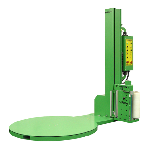
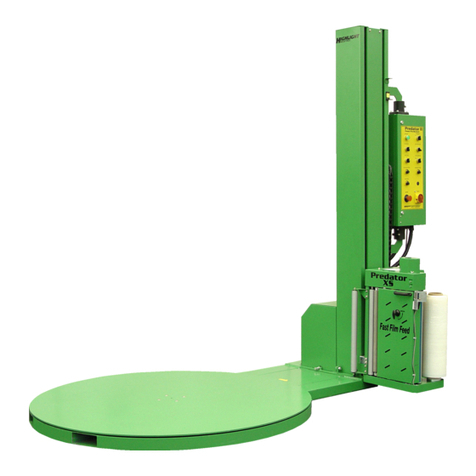
Highlight Synergy 0.5 User manual

SYNERGY 0.5
LOW PROFILE
TURNTABLE STRETCH
WRAPPER
SERIAL NUMBER
Please refer to the serial number in all correspondence with Highlight or
any Highlight Distributor. This identifies your machine and will help in
our ability to quickly and efficiently respond to your needs.
OPERATION MANUAL NUMBER: SYN0.5LPSTD2013 / JULY-2015 / JAN-2019
Operation Manual

Synergy 0.5 Turntable Stretch Wrapper Operation Manual
Highlight Industries, Inc. ● 2694 Prairie SW,Wyoming, Mi 49519 ● 1-800-531-2465 1
Table of Contents............................................................................................................. 1
Table of Figures................................................................................................................ 2
General Information........................................................................................ 3
Safety Messages.............................................................................................................. 4
Introduction and Warranty ................................................................................................ 6
Revision History................................................................................................................ 8
Specifications.................................................................................................. 9
Specifications ................................................................................................................. 10
System Overview Prints.................................................................................................. 11
Installation & Adjustments............................................................................. 12
Machine Placement........................................................................................................ 13
Machine Set-Up.............................................................................................................. 14
Frequency Drive Adjustments......................................................................................... 15
Pre-Operation Adjustments ............................................................................................ 26
Load Compression Testing............................................................................................. 27
Optional Scale Package ................................................................................................. 28
Operation Instructions................................................................................... 31
Film Loading................................................................................................................... 32
Machine Operating Instructions...................................................................................... 33
Film Cutting .................................................................................................................... 34
Maintenance................................................................................................. 35
Preventative Maintenance.............................................................................................. 36
Maintenance Schedule................................................................................................... 38
Trouble-shooting........................................................................................... 39
Troubleshooting Guide ................................................................................................... 40
Power Problems............................................................................................................. 41
Turntable Problems........................................................................................................ 42
Technical References................................................................................... 43
Recommended Spare Parts ........................................................................................... 44
Mechanical Drawings...................................................................................................... 45
Electrical Drawings......................................................................................................... 51
Notes............................................................................................................ 54
Table of Contents

Synergy 0.5 Turntable Stretch Wrapper Operation Manual
Highlight Industries, Inc. ● 2694 Prairie SW,Wyoming, Mi 49519 ● 1-800-531-2465 2
Figure 1: Synergy 0.5 Low Profile, Side View .................................................................... 11
Figure 2: Altivar 12 AC Drive Keypad................................................................................. 15
Figure 3: Film Loading/Threading Diagram........................................................................ 32
Figure 4: Top View of Package, Film Cut Location ............................................................ 34
Figure 5: Side View of Package, Film Tear Angle.............................................................. 34
Table of Figures

1
Highlight Industries, Inc.
Synergy 0.5 Turntable Stretch Wrapper Operation Manual
General
Information

General
Information Synergy 0.5 Turntable Stretch Wrapper Operation Manual
Highlight Industries, Inc. ● 2694 Prairie SW,Wyoming, Mi 49519 ● 1-800-531-2465 4
For the best result with the Synergy Turntable Stretch Wrapper, carefully read this manual
and all of the warning labels attached to the equipment before installing and operating it,
and follow instructions exactly. Keep this manual for machine reference.
Definitions and Symbols
High Voltage!
This symbol indicates high voltage. It calls your attention to items or
operations that could be dangerous to you or other persons operating
the equipment. Read the message and follow the instructions carefully.
Warning!
This symbol indicates a potentially hazardous situation which, if not
avoided, can result to bodily injury, or serious damage to the product.
Notes
This symbol indicates an area or subject of special merit, emphasizing
the equipment’s capabilities, common errors in operation or
maintenance, or other special instructions that can provide benefits to
users.
Safety Messages

General
Information Synergy 0.5 Turntable Stretch Wrapper Operation Manual
Highlight Industries, Inc. ● 2694 Prairie SW,Wyoming, Mi 49519 ● 1-800-531-2465 5
General Precautions –Read These First!
High Voltage!
Disconnect AC input power before checking components, performing
maintenance, cleaning up, and when the machine is not in use. Do NOT
connect or disconnect wires and connectors while power is applied to circuit.
High Voltage!
Wiring work should be carried out only by qualified personnel. Otherwise, there
is a danger of electric shock or fire.
High Voltage!
The user is responsible for conforming to all applicable code requirements with
respect to grounding all requirements. Do NOT use extension cords to operate
the equipment.
High Voltage!
Motor control equipment and electronic controllers are connected to hazardous
line voltages. When servicing drives and controllers, there may be exposed
components with housings or protrusions at or above line potential. Extreme
care should be taken to protect against shock.
Warning!
Loose clothing must NOT be worn while the machine is in operation. Stay clear
of moving parts while the machine is running.

General
Information Synergy 0.5 Turntable Stretch Wrapper Operation Manual
Highlight Industries, Inc. ● 2694 Prairie SW,Wyoming, Mi 49519 ● 1-800-531-2465 6
Introduction
Thank you for your purchase of a Synergy 0.5 Turntable Stretch Wrapper! Designed for the
high volume industrial user the Synergy 0.5 offers the flexibility to precisely adjust the level
of film stretch to match the load-holding requirements.
Limited Warranty
Highlight Industries, Inc. warrants its Synergy manufactured by it, and sold pursuant to this
order, will be of merchantable quality, free from defects in material and workmanship as
determined at the date of shipment, by generally recognized, applicable and accepted
practices and procedures in the industry, for a period of three (3) years from the Highlight
invoice date, under normal use and service.
When the Purchaser gives Highlight written notice of any alleged defect within the
applicable warranty period, Highlight will, at its option repair or replace the same free of
charge F.O.B. its manufacturing plant, installation not included. Equipment replaced under
the warranty shall have the same warranty as new equipment but does not extend the
warranty of the original equipment.
Satisfaction of this warranty, consistent with other provisions herein, will be limited to the
replacement or repair or modification of, or issuance of a credit for, the equipment involved,
at Highlight’s option.
Highlight neither assumes nor authorizes any person to assume for it any other obligation
in connection with the sale of Highlight’s equipment.
This warranty shall not apply to any equipment which has been repaired or altered by un-
authorized personnel in any way so as to, in the judgment of Highlight, affect serviceability,
or which has been subjected to misuse, negligence, accident, or to equipment made by
Highlight which has been operated in a manner contrary to Highlight’s instructions.
In no event regardless of the cause, shall Highlight be liable for penalties or penalty clauses
of any description or any damages resulting from loss of profits, use of products or for any
incidental indirect or consequential damages, even if advised of the possibility of such
damages. This limitation of Highlight’s liability will apply regardless of the form of action,
whether in contract or tort, including negligence. Any action against Highlight must be
brought within twelve (12) months after cause of action accrues.
“This warranty in lieu of all other warranties whether expressed, implied or statutory
including implied warranties of merchantability of fitness or extends only to the buyer or
customer purchasing from Highlight Industries, Inc or an authorized distributor.”
Introduction and Warranty

General
Information Synergy 0.5 Turntable Stretch Wrapper Operation Manual
Highlight Industries, Inc. ● 2694 Prairie SW,Wyoming, Mi 49519 ● 1-800-531-2465 7
About This Document
The purpose of this manual is to provide you with information necessary to install, operate,
troubleshoot, and maintain the Synergy Turntable Stretch Wrapper. The audience for this
manual should have basic knowledge of mechanical and electronic components, standard
electrical wiring practices, and schematics symbols.
To guarantee safe operation of the equipment, carefully observe the safety messages
throughout this manual. Keep this operating manual and distribute it to all users for
reference.
Application Assistance
If any assistance is desired, contact the distributor from whom you have purchased the unit,
or call the number listed on the bottom of each page of this manual. To receive quick and
proper technical support for the equipment you have purchased, please be prepared to
provide the following information:
1. Machine Serial Number
2. Date of Purchase
3. Symptoms of any problems

General
Information Synergy 0.5 Turntable Stretch Wrapper Operation Manual
Highlight Industries, Inc. ● 2694 Prairie SW,Wyoming, Mi 49519 ● 1-800-531-2465 8
Revision
Revision Comment
Date of Revision
Initial Release
April 2011
Updated turntable drawing –ref 2008
Oct 2013-RDU
Updated Film Diagram
July 2015-WBK
Tension Knob Assembly added
Jan 2019-JMR
Revision History

2
Highlight Industries, Inc.
Synergy 0.5 Turntable Stretch Wrapper Operation Manual
Specifications

Specifications Synergy 0.5 Turntable Stretch Wrapper Operation Manual
Highlight Industries, Inc. ● 2694 Prairie SW,Wyoming, Mi 49519 ● 1-800-531-2465 10
Machine Dimensions
Low Profile
Length (inch)
95
Width (inch)
60
Turntable Height from Floor (inch)
3.25
Operation Space (inch)
105 L x 75 W
Maximum Pallet Size (inch)
52 x 52
Shipping Weight (lbs)
1000
Electrical Specifications
120VAC, 60Hz, Single Phase, 15Amp
NEMA 12 Rated Electrical Enclosure
Off the Shelf Components
Turntable
4,000 lbs Maximum Turntable Load Capacity
12 RPM Maximum Turntable Speed
1/2 HP 3-Phase AC Motor
1/2 HP AC Frequency Drive
Specifications

Specifications Synergy 0.5 Turntable Stretch Wrapper Operation Manual
Highlight Industries, Inc. ● 2694 Prairie SW,Wyoming, Mi 49519 ● 1-800-531-2465 11
Note
Shown below are STANDARD assembly drawings. It may not reflect your
purchased system, especially when optional items are added. Refer to the
Technical References section of the manual for more detailed information.
Figure 1: Synergy 0.5 Low Profile, Side View
System Overview Prints

3
Highlight Industries, Inc.
Synergy 0.5 Turntable Stretch Wrapper Operation Manual
Installation &
Adjustments

Installation & Adjustments Synergy 0.5 Turntable Stretch Wrapper Operation Manual
Highlight Industries, Inc. ● 2694 Prairie SW,Wyoming, Mi 49519 ● 1-800-531-2465 13
Receiving and Inspections
The Synergy Turntable Stretch Wrapper has gone through quality control tests at the
factory before shipment. Upon receiving, please do the following:
1. Inspect the entire machine for visual damage during shipment. If found, immediately
report this damage to the trucking line. Highlight Industries, Inc. has taken every
precaution during the packaging and loading of this equipment, however, it is YOUR
RESPONSIBILITY to inspect for damage before installation.
2. Make sure the part or serial number indicated on the machine corresponds with the
part number of your order.
Positioning of the Machine
Place the Synergy Turntable Stretch Wrapper close to an area where you will be wrapping
your loads. Make sure that there is sufficient room to load/unload the machine and that you
do not stretch the power cable. Remember, you will need to plug the machine in to a
120VAC, 15-Amp outlet.
Floor Weight Bearing/Stress Tolerance
The floor must be able to bear the weight of the machine, the weight of the maximum load,
plus a safety factor. The floor must also be able to tolerate the stress of the machine’s
operation. If the fork trucks will operate on the same weight bearing area, add the weight of
the trucks to the weight bearing stress tolerance requirements.
The Synergy can be installed on any type of floor constructions that meets the weight
bearing and stress tolerance requirements.
Warning!
The Synergy must be anchored securely to the floor, using the type of anchor
recommended for your floor.
Machine Placement

Installation & Adjustments Synergy 0.5 Turntable Stretch Wrapper Operation Manual
Highlight Industries, Inc. ● 2694 Prairie SW,Wyoming, Mi 49519 ● 1-800-531-2465 14
Unpacking and Moving the Machine
It is very important to read all instructions before undertaking any of these steps. The
following steps should help achieving a safe and quick machine set-up.
1. Place the skidded machine close to the designated wrap area. Remove all shipping
fasteners holding the machine to the pallet.
2. Place the forks of the forklift through the tubes provided on the base of the machine,
remove the machine from the shipping skids, and place it in the designated wrap
area.
Warning!
It is very important that the machine be leveled. Uneven floors will cause
premature turntable support roller failure.
Power and Control Wiring Checks
1. Using a volt meter, check the AC voltage coming to the machine and insure the
proper voltage is present.
2. Plug the machine in and turn the Power Switch ON. Power should now be applied to
the AC frequency drives.
Machine Set-Up

Installation & Adjustments Synergy 0.5 Turntable Stretch Wrapper Operation Manual
Highlight Industries, Inc. ● 2694 Prairie SW,Wyoming, Mi 49519 ● 1-800-531-2465 15
An AC Frequency Drive is a device that controls the 3-phase AC motor’s speed by varying
the frequency and voltage sent to the motor. The Synergy Turntable Stretch Wrapper uses
Schneider Electric Altivar 12 Adjustable Frequency Drives. Refer to the Electrical
Schematic Drive Parameters Technical References section for detailed drive parameter
settings. Refer to the drive manufacturer’s manual provided on their CD provided with this
machine for more detailed drive information.
Altivar 12 Digital Keypad Description
The digital keypad includes the displays panel and the keypad. The display panel provides
the parameter display and shows the operation status of the AC drive. The keypad provides
programming and control interface.
Figure 2: Altivar 12 AC Drive Keypad
Keypad Description:
1. Value LED. When illuminated it indicates when a numeric value is being displayed.
2. Charge LED. When illuminated it indicates when drive capacitors are fully charged.
Frequency Drive Adjustments

Installation & Adjustments Synergy 0.5 Turntable Stretch Wrapper Operation Manual
Highlight Industries, Inc. ● 2694 Prairie SW,Wyoming, Mi 49519 ● 1-800-531-2465 16
3. Unit LED. When illuminated it indicates when a unit, such as AMPS, is being
displayed.
4. ESC button. Exits a menu or parameter, or aborts the displayed value and returns to
the previous value in the memory.
5. STOP button. Stops the motor. The run command will have to be cycled before the
motor will be allowed to run again.
6. RUN button. Starts running the motor if the drive is configured for control by the
drive keypad.
7. Jog Dial. Used for navigation of the menus. Turn clockwise or counterclockwise to
scroll through the menu list and is used for selection/validation when the dial is
pressed.
8. MODE button. Switches between the control/programming modes.
9. CONFIGURATION mode LED. When illuminated it indicates when a value can be
changed.
10.MONITORING mode LED. When illuminated it indicates when the display is
monitoring the current status of the drive.
11.REFERENCE mode LED. When illuminated it indicates when the display is showing
the speed reference value.
12.Four 7-Segment displays. The display of the drive for menus and settings.
Menu Structure
To access the monitoring parameters, press the wheel on the
face of the frequency drive. Using the wheel, scroll through the
menu until the display shows Non (Mon) for monitoring mode.
This gives the user access to all the monitoring parameters.
To access the complete set of drive parameters first press the wheel to access different
modes. Using the wheel, scroll to “COnF” and press the wheel again; this will access
different sets of parameters. Using the wheel, scroll to “FULL” and press the wheel; this will
give the user access to the complete parameter set.

Installation & Adjustments Synergy 0.5 Turntable Stretch Wrapper Operation Manual
Highlight Industries, Inc. ● 2694 Prairie SW,Wyoming, Mi 49519 ● 1-800-531-2465 17
Monitoring Parameters
Code
Name/Description
Unit
LFr
External reference value:
External keypad or local force mode configured. Forced local reference
FLOC page 61 set to LCC and Forced local assignment FLO page 61
different to nO.
Displays the speed reference coming from the remote keypad. This
value is not visible in factory setting.
Hz
rFr
Output Frequency:
This function provides the estimated motor speed. It corresponds to the
estimated motor frequency (on the motor shaft). In Standard law the
Output frequency rFr is equal to stator frequency. In Performance law
the Output frequency rFr motor speed is equal to the estimated motor
speed.
Range: -400 to 400 Hz
Hz
LCr
Motor Current:
Estimation of the effective motor current from phase current
measurements with an accuracy of 5%. During DC injection, the current
displayed is the maximum value of current injected in the motor.
A
ULn
Main Voltage:
Line voltage from the point of view of the DC bus, motor running or
stopped.
A
StAt
Product Status:
rdY –Drive Ready
rUn –Drive Running
ACC –Acceleration in progress
dEc –Deceleration in progress
dCb –DC injection braking in progress
CLi –Current limit
nSt –Freewheel stop control
Obr –Auto-Adapted deceleration
CtL –Controlled stop on mains phase loss
tUn –Auto-tuning in progress
FSt –Fast stop active
nLP –No line power
N/A

Installation & Adjustments Synergy 0.5 Turntable Stretch Wrapper Operation Manual
Highlight Industries, Inc. ● 2694 Prairie SW,Wyoming, Mi 49519 ● 1-800-531-2465 18
Programming Functions
All functions have been Highlight factory set and tested. The factory settings listed in this
manual are the drive manufacturer’s factory setting, not the Highlight Industries factory
settings. Refer to the Electrical Schematic Drive Parameters page of the Technical
References section for the Highlight factory settings. Some of the most commonly adjusted
programmable functions (parameters) are listed below.
Note
Refer to the drive manufacturers Operation Manual or website for complete lists
and explanations of the programming parameters.
I_O Menu
Code
Sub-
Code
Name/Description
Factory
Setting
tCC
Type of Control:
2C –2-wire control
3C –3-wire control
2C
AI1-
AI1t
Analog Input 1 Type:
5U –0-5VDC input voltage
10U –0-10VDC input voltage
0A –0-20mA current input
5U
r1
Relay Output 1 Assignment:
nO –Not assigned
FLt –No error detected
rUn –Drive run
FLt
AO1-
AO1
Analog Output 1 Assignment:
nO –Not Assigned
OCr –Motor current
OFr –Output Frequency
nO
AO1t
Analog Output 1 Type:
10U –0-10VDC
0A –0-20mA
4A –4-20mA
0A

Installation & Adjustments Synergy 0.5 Turntable Stretch Wrapper Operation Manual
Highlight Industries, Inc. ● 2694 Prairie SW,Wyoming, Mi 49519 ● 1-800-531-2465 19
drC Menu
Code
Sub-
Code
Name/Description
Adjustment
Range
Factory
Setting
bFr
Standard Motor Frequency
50/60
50 Hz
nPr
Rated Motor Power (% of drive rated HP)
0.5-1.2
1
UnS
Rated Motor Voltage
100-480V
230V
nCr
Rated Motor Current
plate
Varies
FrS
Rated Motor Frequency
10-400Hz
50 Hz
nSP
Rated Motor Speed
0-24000rpM
Varies
tFr
Maximum Frequency
10-400Hz
72 Hz
Ctt
Motor Control Type:
PErF –Performance, Sensorless Vector
Std –Standard, Volts/Hertz
PUNP –Pump, low torque
Std
UFr
IR Compensation:
Optimizes torque at very low speeds
25-200%
100%
SLP
Slip Compensation
0-150%
100%
StA
Frequency Loop Stability:
Adjusts overshoots and oscillations at the end
of acceleration or deceleration. A higher
number decreases oscillations
0-100%
20%
FLG
Frequency Loop Gain:
Adjusts the slope of the speed increase. A
lower number decreases oscillations.
0-100%
20%
tUn
Motor Auto Tuning:
Automatically tunes the drive to the motor
profile
nO/YES/dOnE
nO
Table of contents
Other Highlight Packaging Equipment manuals
Popular Packaging Equipment manuals by other brands

EC-PACK
EC-PACK EC-JET 2000 manual

Fimap
Fimap FV9+ B Use and maintenance manual
SCHÜTZ
SCHÜTZ ECOBULK WITH IMPELLER operating manual
NEUBRONNER
NEUBRONNER ALPHA X1-400 operating manual
Minipack-Torre
Minipack-Torre SC55 Installation, operation and maintenance

Audion Elektro
Audion Elektro Sealmaster MAGNETA MG 300 Instructions for use
SealerSales
SealerSales FS-205 operating instructions

Promax
Promax DC-800-P-H Operation manual
Teknika
Teknika MUL-350 Adjustment instructions
Advanced Poly-Packaging
Advanced Poly-Packaging Advanced Poly-Bagger T-1000 Operation guide

U-Line
U-Line Green Machine H-3518 instructions

Sealed Air
Sealed Air Fill-Air Rocket user guide
