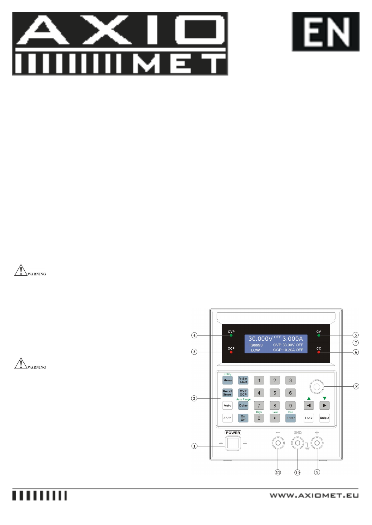
(the knob can be used together with [<] or [>] to adjust the
resolution).
Set the desired output voltage value.
Press [V-Set/I-Set] until “Voltage” is shown on the LCD,
the panel operation is set to voltage value input mode, set the
desired change value by using the number key or the knob
(the knob can be used together with [<] or [>] to adjust the
resolution).
Start the output.
Press [Output] to enable output, now, the meter displays the
actual output measurement value.
Constant voltage mode confirmation.
Check whether the CV indicator is on or not to make sure the
output operation is under the constant voltage mode. If the
CC indicator is on, it needs to enlarge its current limit value
to assure that the output operation is under constant voltage
mode.
8.25.3. Constant Current Operation
Connect load to output terminal.
For the safety, when connect the load to output terminals of
(+) and (-), it must turn off the power.
Select output range.
Turn on the power after the load is well connected, select the
adequate operation range by pressing [High] or [Low].
Set the voltage limit value.
Press [V-Set/I-Set] until “Voltage” is shown on the LCD,
the panel operation is set to voltage value input mode, set the
desired change value by using the number key or the knob
(the knob can be used together with [<] or [>] to adjust the
resolution).
Set the desired output current value.
Press [V-Set/I-Set] until “Current” is shown on the LCD, the
panel operation is set to current value input mode, set the
desired change value by using the number key or the knob
(the knob can be used together with [<] or [>] to adjust the
resolution).
Start the output.
Press [Output] to enable output, now, the meter displays the
actual output measurement value.
Constant current mode confirmation.
Check whether the CC indicator is on or not to make sure the
output operation is under the constant current mode. If the
CV indicator is on, it needs to enlarge its voltage limit value
to assure that the output operation is under constant current
mode.
8.25.4. Store and Recall Operation
The storing setting function includes the store of the Output
range, Output voltage value, Output current value, Over
Voltage Protection level, Over Current Protection level,
Over Voltage Protection status, Over Current Protection sta-
tus and the Delay time.
Store the present setting status to the memory bank.
Press [Recall/Store] until “Utility Store” is shown on the
LCD, set the panel operation to storing setting selection,
input the desired memory address by using number key or
knob, then press [Enter] to complete the change of store.
Recall the setting status from the memory bank.
Press [Recall/Store] until “Utility Recall” is shown on the
LCD, set the panel operation to recall setting selection, use
the number key or knob to recall the desired memory address,
then press [Enter] to complete the change of recall.
8.25.5. Auto Running Operation
The function must be used together with the Delay setting
which is defined as the operation delay time of next running
operation. The Delay function is workable only under Auto
Running operation.
The setting and store of very group of data.
A group setting includes the Output range, Output volt-
age value, Output current value, Over Voltage Protection
level, Over Current Protection level, Over Voltage status
(ON/OFF), Over Current status (ON/OFF), and Delay time.
User can proceed the setting and store it to the memory bank
group by group up to 100 groups maximum.
Recall range setting (Auto running operation range).
Regarding the setting description, please refer to Auto Range
operation in section 3.5.
Enter Auto mode by pressing [Auto], now, the operation is
in the auto running function.