Axio MET AX-3004H User manual

1. Introduction
Thank you for selecting the Axiomet AX-3004H Switching DC Power Supply, please read this user guide
before the operation.
2. Safety
This manual contains important safety and operation instructions for correct use of power supply. Read
through the manual and pay attention to the markings and labels of this unit to be connected.
Do not install the substituted parts or operate the modification without permission, please contact
your distributor repair, questions, or for warranty replacements to guaranty of the stability of the unit.
Pay special attention to the information of WANRINGS or CAUTIONS to avoid the damage to
power supply or connected equipment, which could lead to human injury.
Please contact your distributor or the trained technicians for repair service.
3. Safety Marks
WARNING:
Failure to observe this warning may cause injury to persons and damage to power supply or connected
equipment.
CAUTION:
Failure to observe this warning may result in damage to equipment and improper functioning of power
supply.
Protective conductor terminal

DANGER - High voltage
ATTENTION on the warning or caution
4. Specification Compliance
AX-3004H Switch mode DC Power Supply is compliance with the specification described in this manual.
The content or specification of this manual is subject to change, without prior notice.
5. Product Features
The AX-3004H is the single output switch mode DC power supply with max. 30V output voltage, 3.75A
output current and maximum output power as 50W.
AX-3004H integrates the AC/DC and DC/DC 2nd level voltage regulator technology, the AC/DC in-
put is adapting the worldwide voltage range. The DC/DC uses a buck converter, which is highly efficiency
and high speed dynamic response performance.
AX-3004H can set the voltage and current through the keypad of front panel and save the setting
groups for efficient and functional usage.
AX-3004H also features a four-digit voltage and current meter, as well as the compact handheld
size. The AX-3004H is perfect for solving a variety of loading conditions and applications.
The main features of the AX-3004H include:

� Handheld design
� Fanless cooling for silent operation
� Four digit LCD display
� Output short circuit protection
� High speed dynamic response
� Automatic protection under power off status
� Automatic output recognition of USB charging port
6. Quick Start
This chapter describes the basic check points on AX-3004H for proper operation, as well as the functions of
AX-3004H.

7. Front Panel Description
1. Current Setting Indicator
2. Voltage Setting Indicator
3. Measured Value Display
4. Keypad
5. USB Charging Ports
6. DC Output Terminals

8. Pre-Checking
Before the operation, please check the included accessories; if any are missing, please contact the local
distributor.
Power Cord – 1PC
User Guide – 1PC
Connect with power cord to the unit and to a properly grounded outlet, and switch on AX-3004H.
The unit starts the self-system checking, the LCD displays 0.5s, date of manufacturing, production lot,
model number in turn.
9. Quick Start
OUT Button
Press the OUT button to begin outputting the selected voltage and current. The unit will display the
voltage or current on the screen. Press again OUT button to exit output function.
UP Arrow Key + DOWN Arrow Key
Press UP arrow key to activate the LCD backlit
Press DOWN arrow key to exit the LCD backlit
LEFT Arrow Key + RIGHT Arrow Key
Press LEFT arrow key to decrease the contrast of LCD
Press RIGHT arrow key to increase the contrast of LCD
V/A Key
Press the V/A key to activate voltage measurement and read the voltage value from display.
Push the V/A key again to switch current measurement and read the current value from the display
USB Button
Push the USB button and adjust voltage to 5.2V and the current as 3A to enter USB
power charging mode; then, push the OUT button to output the selected 5.2V at 3A.
Push the USB button again and USB button light out to exit USB power charging mode.
SET Button + V/A Button + Direction Arrow Keys
Push the SET button, and press the direction arrow keys to adjust the voltage value setting, Push the V/A
button to switch to the current value setting, and press the direction arrow keys to measured current value.

10. Output Checking
10.1. The output voltage regulation mode check
This is for checking the functions of power supply under non-load voltage stability.
1) Switch on the product, the power is off and the indicators of CC & CV are light off.
2) Push the OUT button, the CV indicator is shown on the LCD display.
3) Setting the voltage of power supply:
Push the V/A button and shift to voltage display mode. Then adjust voltage values, and the voltage value
displayed on the LCD is approaches the settled value and within tolerance, current value is showed as 0A.
4) Make sure the voltage can be adjusted from 0.3V to max. 30V.
10.2. The output constant current mode check
This is for checking the functions of power supply under constant current mode.
1) Switch on the product, the power is off and the indicators of CC & CV are off.
2) Adjust voltage value to 30V.
3) Connect the resistance (3Ω/50W) between output terminals.
4) Push the OUT button, the indicator of CC is also displays on the LCD.
5) Setting the current of power supply:
Push V/A button and shift to current display mode. Then adjust current values, and check that the current
value displayed at LCD is approaching the settled current value and within the tolerance.
6) Make sure the current can be adjusted from 0A to the maximum value.
10.3. The output short circuit protection check
This is for checking the function of short circuit protection of output.
1) Switch on the product, the power is off and the indicators of CC & CV are light off.
2) Adjust voltage value is over 5V and current value is over 1A.
3) Push the OUT button.
4) Connect the output terminals by wire for short circuit, the light of OUT button is off and output off.

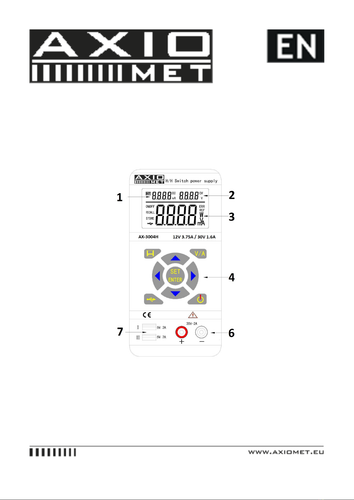
11. The USB charging function check
This is for checking USB charging function.
1) Switch on the product, the power is off and the indicators of CC & CV are light off.
2) Push and light the USB button. Adjust the voltage as 5.2V and current as 2.5A.
3) Push and light OUT button.
4) Make sure the power supply under CV mode, the CV indicator is light in LCD.
5) Setting the current value and make sure the current value can be adjusted from 0A to the maximum
value of measuring range. You cannot adjust voltage.
12. Major Specification
Input Voltage: 90VAC~265VAC 43Hz~65Hz ±2Hz
Input Current: 1A
Output Rating: Max. Voltage 0.3V~30V, Max. Current 0~3.75A
Line Regulation ±%of output + offset: Voltage CV�0.01%+3mV, Current CC�0.01%+3mA
Load Regulation ±%of output + offset: Voltage CV�0.02%+3mV, Current CC�0.02%+3mA
Measurement Accuracy: Voltage 10mV, Current 1mA
Measured Value Accuracy @ 25℃ ±%of output + offset: Voltage �0.05%+5mV, Current �0.05%+5mA
Measurement Speed: Voltage 100ms/ones, Current 100ms/ones
Setting Value Accuracy @ 25℃ ±%of output + offset: Voltage �0.05%+5mV, Current �0.05%+5mV
Ripple and Noise 20HZ-20MHZ: Voltage �10mVrms/100mVp-p, Current�10mVrms/100mVp-p
Temperature Coefficient @ 0~40℃ ±%of output + offset: Voltage �0.05%, Current �0.1%
Dimensions: 185x88x38 mm
Weight (Net): 370g
13. Supplementary Characteristic
Build-in EEPROM
Recommended Calibration Time:Annually
AC Input Power: 90-265VAC, 43 to 65 Hz
Operating Temperature: 0 to 40 ℃
Storage Temperature: -20 to 70 ℃

14. Operation
Check the rating label of the power supply and ensure that it complies with the AC voltage that is to be used.
Connect the power supply to the AC outlet the provided power cord.
15. Keypad Description
OUT Output check
V/A Voltage & Current Shift
USB 5V Charging
SET/ENTER Voltage & Current Setting/Enter
STORE/RECALL Data Saving/Recall
UP DOWN LEFT RIGHT Direction Arrow Keys
16. Front Panel
After power on, the panel operation and all the functional buttons can be operated.
17. Voltage Setting
The voltage setting range is from 0.30V to 30V; follow the setting steps as below:
1. Switch on the power supply
2. Push the OUT button to stop the output
3. Push the SET/ENTER button, the max value flashes in the voltage setting area
4. Push the LEFT or RIGHT arrow keys to move the cursors
5. Push the UP or DOWN arrow keys to change the settings
6. Push SET/ENTER button to exit voltage setting mode
UP ENTER
OUT �SET � 0 0.0 0 V ------------- >3 0.0 0 V ---------------> OK
Remark:

I. It is possible to set voltage values once the outputs are valid. However, for protection of the load,
it is recommended to stop output before voltage setting.
II. Due to the total power limit, current settings will be decreased automatically as
voltage setting increasing.
18. Current Setting
The current setting range is from 0.000A to 3.750A, follow the setting steps as below:
1. Switch on the power supply
2. Push the OUT button to stop the output
3. Push the SET/ENTER button, the max value position flashes of voltage setting area.
4. Push the V/A button, the max. value position of current setting flashes and current setting is activated
5. Push the LEFT or RIGHT arrow keys to move the cursors
6. Push the UP or DOWN arrow keys to change the settings
7. Push SET/ENTER button to exit current setting mode
UP ENTER
OUT �SET �V/A �0. 000 A ---------> 2.000 A ------------ > OK
Remark:
I. It is possible to set current values once the outputs are valid. However, for protection of the load, it is
recommended to stop output before current setting.
19. Output Switch
Under the panel operating mode, push OUT button to shift output status. Once OUT button is on and lit
up, the measured values displayed at LCD; push OUT button again to exit output mode.

20. Data Saving Operation
1. Under the voltage setting or current setting mode, push the STORE button to save the values of voltage
or currents into memory of power supply for future recall purpose.
2. Refer 3.3 or 3.4 for voltage or current setting mode.
3. Push STORE button to enter data saving mode, the minimum value position flashes and displays
STORE icon on LCD.
4. Move UP or DOWN arrow keys to select storage group serial number.
5. Click ENTER button to confirm data saving, click STORE button to exit data saving mode.
UP
SET � STORE �� 1 ��2 ��ENTER -----> OK
21. Recall Saving Operation
Under the panel operating mode, push the RECALL button for retrieving the saved data from memory;
following the setting steps as below:
1. Switch on the power supply
2. Push RECALL button to enter data recall mode, the minimum value position is flashes and displays
RECALL icon on LCD.
3. Press UP or DOWN arrow keys to recall the stored group number, the default values from voltage or
current setting mode displayed in LCD.
4. Press ENTER button to confirm data recall, or press STORE button to exit data recall mode.
UP
RECALL ��1 ��2 ��ENTER --------> OK
22. USB Power Charging
Push the USB button, the default setting is voltage @ 5.2V and current @ 2.5A, the LCD will display 5.2V,
with current value as 0A. Connect the mobile phone via USB cable for power charging or supply USB
power to any compatible device.
For battery charging, the USB ports are suitable for mobile phones. With automatic check func-

tion, the supply will set the proper charging current automatically.
1. Push the OUT button to activate output mode.
2. Push the USB button and USB indicator will turn off to exit USB charging mode.
USB � OUT � OK
23. Calibration
Follow the below chart, connect the 5 digit displayed volt meter and current meter, please resistance
(10Ω/100W) into the output terminals. To calibrate, start from point of zero voltage – voltage
coefficient – and zero current – current coefficient.
Hold the SET button to switch on power supply until “REF” displayed in LCD to enter calibration
mode.
24. Voltage Calibration
At the power supply displayed 2.000A & 05.00V in setting area of LCD and **.**V displayed in main part
of LCD. Connect the output terminal with an external reference voltage meter and shift to CV mode. Hold

the LEFT or RIGHT arrow keys to move the cursors to left or right and push the UP or DOWN arrow keys
to adjust the values same as readings of external reference voltage meter, then click ENTER button to
finish the voltage bias calibration.
At the power supply displayed 2.000A & 30.00V in setting area of LCD, hold the LEFT or RIGHT
arrow keys to move the cursors to left or right and push the UP or DOWN arrow keys to adjust the values
same as readings of external reference voltage meter, then click ENTER button to finish the voltage gain
calibration.
25. Current Calibration
Push the V/A button and power supply displayed 0.500A & 30.00V in setting area of LCD and *.***A
displayed in the main part of LCD. Connect the output terminals with the external reference current
meter and the load (5Ω/100W), shift to CC mode. Hold the LEFT or RIGHT arrow keys to move
the cursors to left or right and push the UP or DOWN arrow keys to adjust the values same as read-
ings of the external reference current meter. Then click ENTER button to finish the current bias calibration.
While t the power supply displays 2.750A & 30.00V in the setting area of LCD, hold the LEFT or
RIGHT arrow keys to move the cursors to left or right and push the UP or DOWN arrow keys to adjust
the values same as readings of external reference voltage meter. Then click ENTER button to finish the
current gain calibration.
Push OUT button to exit and restart the power supply to complete the calibration function.
Table of contents
Other Axio MET Power Supply manuals
Popular Power Supply manuals by other brands

Raycap
Raycap PowerPlus System 100-3-1U Series Installation instructions operations manual

Thermal Arc
Thermal Arc Fabricator 250C III Operation manual

Velleman
Velleman LABPS3005N user manual

Tektronix
Tektronix TM 515 instruction manual

Sonelco
Sonelco P3270 manual

Caen
Caen EASY3000 Technical information manual