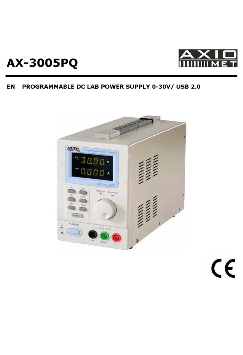
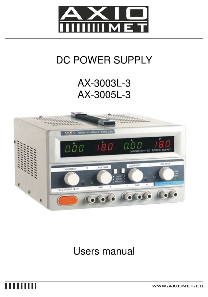
Axio MET AX-3005DBL User manual

REGULATED DC POWER SUPPLY
AX-3005DBL-one channel
AX-3005DBL-3-three channel
Instruction Manual

1. Instalation and handling precautions
When plac ng the Power Supply n serv ce at your workplace, observe the follow ng precaut ons for
best nstrument performance and longest serv ce l fe.
1) Avo d plac ng th s nstrument n an extremely hot or cold place. Spec f cally, don’t leave
th s nstrument n a closed car, exposed to sunl ght n m dsummer, or next to a space
heater.
2) Don’t use th s nstrument mmed ately after br ng ng t n from the cold. Allow t me for t
to warm to room temperature. S m larly don’t move t from a warm place to a very cold
place, as condensat on m ght mpa r ts operat on.
3) Do not expose the nstrument to wet or dust env ronments.
4) Do not place l qu d-f lled conta ners (such as coffee cups) on top of th s nstrument. A sp ll
could ser ously damage the nstrument.
5) Do not use th s nstrument where t s subject to serve v brat on, or strong blows.
6) Do not place heavy objects on the case, or otherw se block the vent lat on holes.
7) Do not use th s Power Supply n strong magnet c f elds, such as near motors.
8) Do not nsert w res, tools, etc, through the vent lat on holes.
9) Do not leave a hot solder ng ron near the nstrument.
10) Do not place th s nstrument face down on the ground, or damage to the knobs may
result.
11) Do not connect other power source to +.- of the output term nal.

2. Specifications
Model AX-3005DB AX-3005DB -3
IPUT
VOLTAGE
230V / 110V ±10% 50~60Hz
OUTPUT
VOLTAGE
0 ~ 30V 2x0~30V
5V
CURRENT
STEPWISE
50mA±5mA 50mA±3mA
OUTPUT
CURRENT
0~5A 2x0~5A, 3A
LINE
REGULATION
CV ≤ 0.02% + 2mV
CC ≤ 0.05% + 5mA
LOAD
REGULATION
CV ≤ 0.02% + 2mV
CC ≤ 0.05% + 5mA
RIPPLE & NOISE
CV ≤ 0.5mV
CC ≤ 2mA
OPERATING
TEMPERATURE
0~40°C
RELATIVE HUMIDITY ≤ 90%

3. Panel details – single type
Figure 1
1) Output Voltage LCD D splay.
2) Output Current LCD D splay.
3) On/Off Power Sw tch.
4) Output term nals.
5) Extended Output Term nals.
6) Constant Voltage D splay.
7) Constant Current D splay.
8) Current L m t Adjustment Ind cator.

9) C.V. / C.C. Select on Sw tch.
10) Current L m t Down Sett ng.
11) Current L m t Up Sett ng.
12) Output Voltage sett ng.
3.1. Constant current adjustment method
1) Adjust by turn ng the voltage sett ng knob to des red voltage.
2) Press the CV/CC sett ng button down to l ght up the CC/CV sett ng nd cator.
3) Use a w re to shorten the (+) and (-) term nal at the output term nal.
4) Push the UP or DOWN button to obta n the des red current value.
5) When push ng and hold the UP or DOWN button over 0.8 sec, the value w ll go up or go
down cont nuously.
6) Release the shortend w re, connect the load to beg n operat on.
7) The sett ng of current value w ll be stored n the EEPROM after power off.
8) The current value w ll be resumed by push ng the CV/CC button when next power on.
4. Panel details – dual type

Figure 2
1) Constant Voltage D splay – Ch.1
2) Output Voltage D splay – Ch.1
3) Constant Current D splay – Ch.1
4) Output Current D splay – Ch.1
5) Current L m t Adjustment Ind cator – Ch.1
6) Current L m t Up Sett ng – Ch.1
7) Current L m t Down Sett ng – Ch.1
8) C.V. / C.C. Select on Sw tch – Ch.1
9) Output Voltage Sett ng – Ch.1

10) Output Term nal – Ch.1
11) Extended Output term nals – Ch.1
12) Ser al Funct on Select Sw tch
13) Ser al Funct on Ind cator
14) PARALLEL Funct on Ind cator
15) PARALLEL Funct on Select Sw tch
16) Constant Voltage LCD D splay – Ch.2
17) Output Voltage LCD D splay – Ch.2
18) Constant Current D splay – Ch.2
19) Output Current D splay – Ch.2
20) Current L m t Adjustment Ind cator – Ch.2
21) C.V. / C.C. Select on Sw tch – Ch.2
22) Current L m t Down Sett ng – Ch.2
23) Current L m t UP Sett ng – Ch.2
24) Output Voltage Sett ng – Ch.2
25) Output Term nals – Ch.2
26) Extended Output Term nals – Ch.2
27) Output Term nals for 5V 3A – Ch.3
28) Power Sw tch
4.1. Constant voltage setting method
1) Turn on power sw tch.

2) Adjust voltage sett ng knob to the des red voltage wh ch can be shown n the LCD d splay.
3) Connect the load, make sure the load current not exceed ng the max mum output current.
4.2. Constant current adjustment method
1) 1.Adjust by turn ng the voltage sett ng knob to des red voltage.
2) Press the CV/CC sett ng button down to l ght up the CC/CV sett ng nd cator.
3) Use a w re to shorten the (+) and (-) term nal at output term nal.
4) Push the UP or DOWN button to obta n the current value.
5) When push ng and hold the UP or DOWN button over 0.8 sec, the value w ll go up or go
down cont nuously.
6) Release the shortend w re, connect the load to beg n operat on.
7) The sett ng of current value w ll be stored n the EEPROM after off.
8) The current value w ll be resumed by push ng the CV/CC button when next power on.
5. Serial function operating method
1) Turn on the power by press ng the POWER sw tch.
2) Push the SERIAL button down to l ght up the nd cator, the dual power supply s now
work ng under ser al cond t on, the max mum voltage output s from 0~60V.
3) When adjust ng both the voltage sett ng knobs ndependently, the total output voltage s
the sum of 2 voltage read ngs from the LCD d splay.
4) Push the SERIAL button down aga n, the nd cator w ll be off, and th s dual power supply
w ll work ndependently.
Notice: When operating at constant current condition, the constant current value should be set
at the same value.

Figure 3
6. Parallel function operating method
1) Turn on the power by press ng the POWER sw tch.
2) Under normal cond t on, to adjust both voltage knob to obta n same or s m lar voltage
value.
3) Push the PARALLEL button down to l ght the nd cator, the un t s now work ng under
parallel cond t on, the max mum current poss bly obta ned s 6A(3003II), 10A(3005XII).
4) To obta n des red voltage by f ne tun ng any of the voltage sett ng knob.
5) Push the PARALLEL button down aga n, the l ght w ll be off, th s dual power supply w ll
operate ndependently.
Figure 4
7. Dual function

W th th s funct on, you can s multaneously ground channel 1 and channel 2 to get +30V and –30V
outputs, proceed as follows :
1. F rst do not turn on power.
2. Short the output (+) term nal of channel 1 and channel 2 w th a short w re.
3. Turn on the power sw tch, push “ser al” button down to l ght up the nd cator, and you
can get negat ve output voltage of 0~30V from channel 1 and pos t ve output voltage of
0~30V from channel 2. as shown n the d agram.
4. In order to l m t the current for +/- supply, you can perform the sett ng of CV/CC
procedures to get the des red current output.
5. Do not forget to remove short w re of output term nals when operat ng n other mode.
Figure 5
8. Notices
1) When the operat on s under PARALLEL cond t on, when act vat ng the SERIAL button, the
operat on w ll be changed from PARALLEL cond t on to SERIAL cond t on.
2) When the operat on s under SERIAL cond t on, when act vat ng the PARALLEL button, the
operat on w ll be changed from SERIAL cond t on to PARALLEL cond t on.
3) When the un t s used n nductance load (l ke DC electr c buzzer), nstall a 4,700uF ~
2,200uF/50V electrode capac tor across the extens on term nal, connect on please refer
to F g 8

4) When the un t s used w th the h gh frequency nstruments (l ke ultrason c solder ng tool),
the electr c power supply should be grounded.
Figure 6
This manual suits for next models
1
Table of contents
Other Axio MET Power Supply manuals
Popular Power Supply manuals by other brands

ETC
ETC F-Drive FD-RPS-48-1000 installation guide

CCS
CCS PSB Series Operation manual

Brooks Instrument
Brooks Instrument 0260 quick start guide

Salicru
Salicru ILUEST NE Series User and operating manual

SOMFY
SOMFY animeo 1860093 installation guide

Ultra Products
Ultra Products 450 Watt ATX Power Supply quick guide