AXIOMATIC AX140900 User manual

User Manual UMAX140900
Version 5
Firmware 5.xx
USER MANUAL
Ethernet to CAN Converter
P/N: AX140900
In Europe:
Axiomatic Technologies Oy
Höytämöntie 6
33880 Lempäälä - Finland
Tel. +358 103 375 750
Fax. +358 3 3595 660
www.axiomatic.fi
In North America:
Axiomatic Technologies Corporation
5915 Wallace Street
Mississauga, ON Canada L4Z 1Z8
Tel. 1 905 602 9270
Fax. 1 905 602 9279
www.axiomatic.com

UMAX140900. Ethernet to CAN Converter. Version 5
ii
ACRONYMS
A
Ampere
ARP
Address Resolution Protocol
°C
Celsius (degree)
CAN
Controller Area Network
CE
Conformité Européenne (European Conformity)
EA
Electronic Assistant®. PC application software from Axiomatic
EEPROM
Electrically Erasable Programmable Read-Only Memory
EMC
Electromagnetic Compatibility
ESD
Electrostatic Discharge
FCC
Federal Communications Commission
G
Acceleration in Gravity Units
GPL
General Public License
hr
hour
HTTP
Hypertext Transfer Protocol
ICMP
Internet Control Message Protocol
ID
Identifier
IEC
International Electrotechnical Commission
IP
Internet Protocol or Ingress Protection (for housing)
ISO
International Organization for Standardization
L
Length (for size)
LAN
Local Area Network
LED
Light-Emitting Diode
m
meters
MAC
Media Access Control (address)
MDIX
Medium Dependent Interface Crossover (MDI-X)
ms
millisecond
PA
Polyamide
PHY
Physical Layer Transceiver (Ethernet chip)
P/N
Part Number
PoE
Power Over Ethernet
RoHS
Restriction of Hazardous Substances
RTOS
Real-Time Operating System
SP
Service Pack
SSP
Software Support Package
SW
Software
TCP
Transmission Control Protocol
UDP
User Datagram Protocol
UL
Underwriters Laboratories (safety organization)
USB
Universal Serial Bus
V
Volt
VDC
Volt Direct Current
W
Watt or Width (for size)
WAN
Wide Area Network

UMAX140900. Ethernet to CAN Converter. Version 5
iii
TABLE OF CONTENTS
1INTRODUCTION .................................................................................................................4
2CONVERTER DESCRIPTION.............................................................................................5
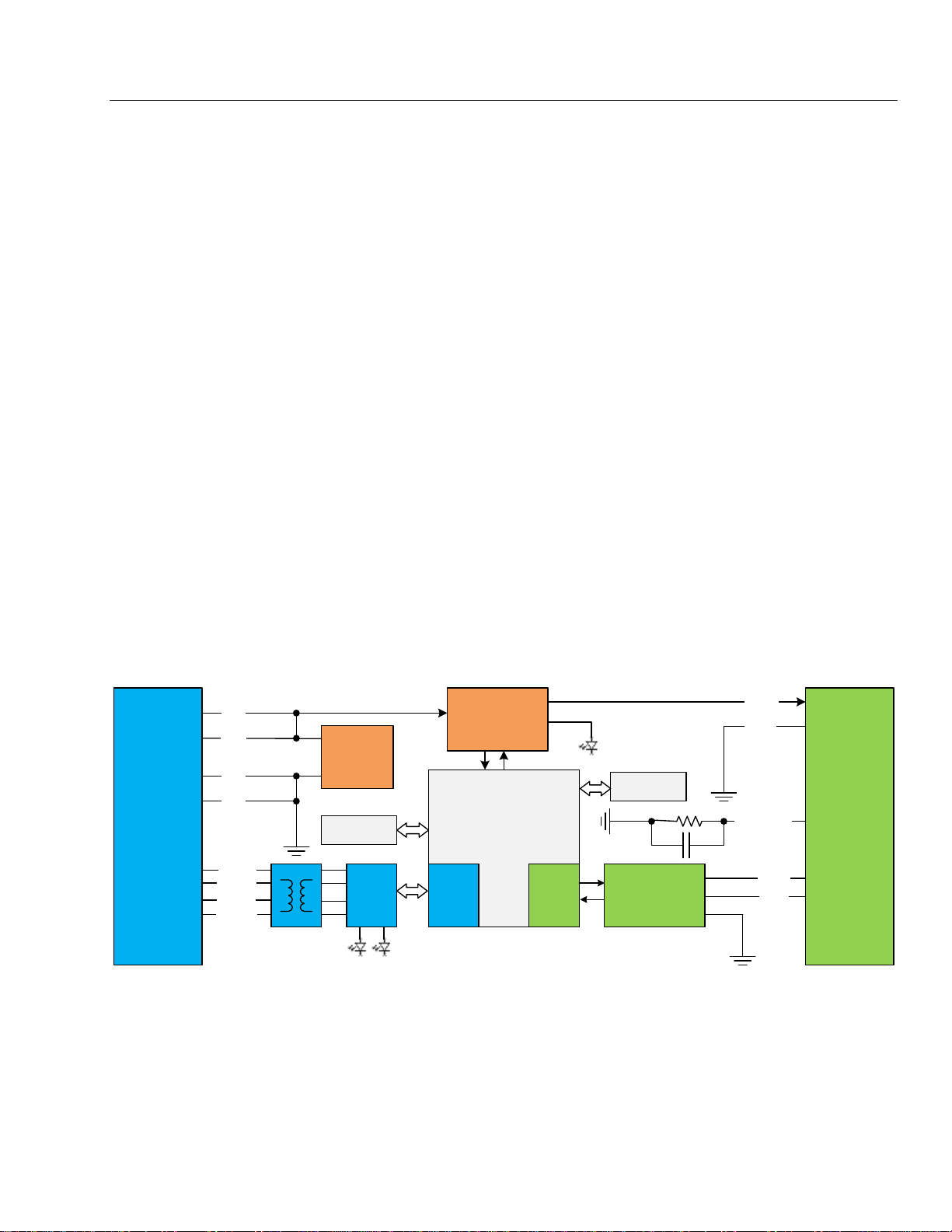
2.1 Hardware Block Diagram.................................................................................................5
2.2 LED Indicators.................................................................................................................6
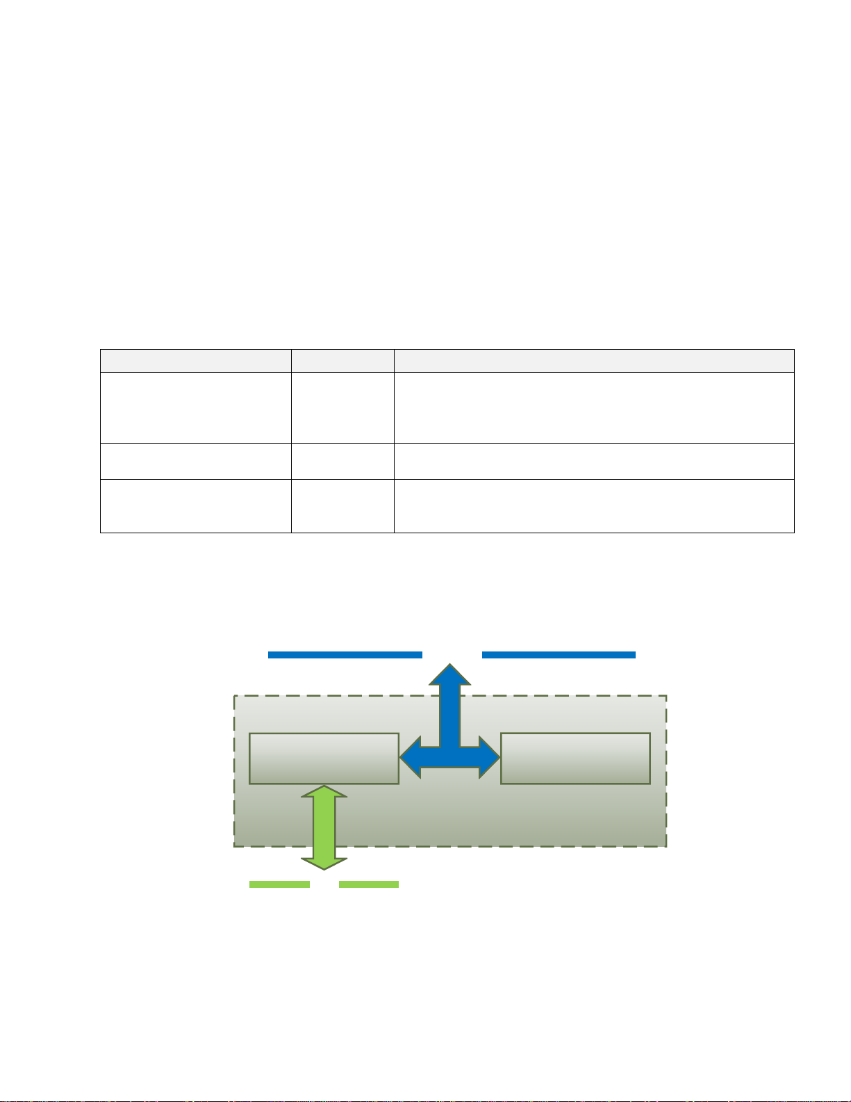
2.3 Firmware Organization....................................................................................................6
2.3.1 Communication Device ...............................................................................................7
2.3.1.1 UDP Protocol ..............................................................................................................7
2.3.1.2 TCP Protocol...............................................................................................................8
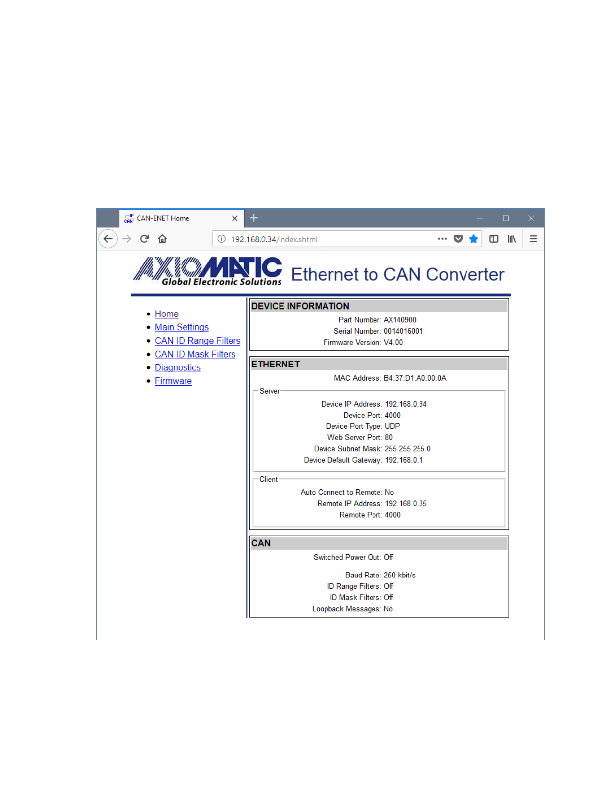
2.3.2 Web Server.................................................................................................................9
2.3.3 Firmware Updates.......................................................................................................9
2.3.4 Network Discovery ......................................................................................................9
3CONVERTER CONFIGURATION .....................................................................................10
3.1 Changing Configuration Parameters .............................................................................11
3.2 Ethernet Configuration...................................................................................................14
3.3 CAN Configuration.........................................................................................................14
3.3.1 CAN ID Range Filters................................................................................................15
3.3.2 CAN ID Mask Filters..................................................................................................16
4CONVERTER DIAGNOSTICS...........................................................................................18
4.1 Health Status.................................................................................................................18
4.2 Converter Rebooting .....................................................................................................19
5FIRMWARE UPDATE........................................................................................................20
5.1 Uploading the New Firmware ........................................................................................20
5.2 Applying the New Firmware...........................................................................................21
6CONVERTER DEPLOYMENT...........................................................................................22
6.1 CAN Network Synchronization ......................................................................................22
6.1.1 Hardware Setup ........................................................................................................22
6.1.2 Converter Configuration............................................................................................23
6.1.2.1 Server Configuration .................................................................................................23
6.1.2.2 Client Configuration...................................................................................................24
7CONVERTER DISCOVERY..............................................................................................27
8TECHNICAL SPECIFICATIONS........................................................................................28
8.1 Power Supply ................................................................................................................28
8.1.1 Input..........................................................................................................................28
8.1.2 Output .......................................................................................................................28
8.2 Ethernet.........................................................................................................................28
8.2.1 Ethernet Connector...................................................................................................29
8.3 CAN...............................................................................................................................29
8.3.1 CAN Connector.........................................................................................................29
8.4 General Specifications...................................................................................................30
8.5 Accessories...................................................................................................................30
8.6 Housing .........................................................................................................................31
9THIRD PARTY SOFTWARE LICENSE NOTICES ............................................................32
10 VERSION HISTORY..........................................................................................................34

UMAX140900. Ethernet to CAN Converter. Version 5 Page: 4-35
1 INTRODUCTION
The following user manual describes architecture, functionality and configuration parameters of
the Ethernet to CAN Converter. It also contains technical specifications and installation
instructions of the converter.
The user should check whether the application firmware installed in the converter is covered
by this user manual. It can be done using any web browser connected to the converted over
the Ethernet connection, see: Configuration Parameters section for more details.
The user manual is valid for application firmware with the same major version number as the
user manual. For example, this user manual is valid for any application firmware version 5.xx.
Updates specific to the user manual are done by adding letters: A, B, …, Z to the user manual
version number.

UMAX140900. Ethernet to CAN Converter. Version 5 Page: 5-35
2 CONVERTER DESCRIPTION
The Ethernet to CAN Converter is a simple device converting CAN frames into UDP or TCP IP
datagrams and sending them over the Ethernet network. The device can also convert UDP or
TCP datagrams into CAN frames.
The converter has one CAN and one Ethernet port. It supports a high-speed CAN with baud
rate up to 1Mbit/s and a fast 100Mbit/s Ethernet. All standard and extended CAN frames,
including data and remote frames, are supported.
The power can be passed through to the CAN port. Protection is provided.
The converter contains a web server to setup configuration parameters and monitor the
internal state of the converter using a web browser. The user can also update the converter
firmware using the web browser.
A simple command-line AxioDisc.exe Windows application is provided to locate a converter
on the LAN.
To ensure low latency in processing CAN and Ethernet messages, the converter software runs
under control of a real-time operating system.
The converter is designed to work on off-road machinery or in a harsh industrial environment
with power transients, high humidity, and vibrations.
2.1 Hardware Block Diagram
The converter hardware block diagram is presented in Figure 1.
PHY MAC CAN
Microcontroller CAN
Connector
CAN
Transceiver
ETH_TX-
Ethernet
Connector
ETH_TX+
ETH_RX-
ETH_RX+
CAN_H
CAN_L
Power
Supply
BAT +
BAT -
Switch
POUT +
POUT -
CAN_SHIELD
EEPROM
BAT+
BAT -
Ethernet Link/Act
Power
FLASH
Ethernet 10/100
Figure 1. The Converter Hardware Block Diagram
The converter is powered from the Ethernet connector using dedicated power lines. The power
from the Ethernet connector can be delivered to the CAN connector through a switch
controlled by a microcontroller.
The Ethernet transformers with PHY, together with the CAN transceiver, provide Ethernet and
CAN physical interfaces.

UMAX140900. Ethernet to CAN Converter. Version 5 Page: 6-35
A powerful ARM Cortex-M4 microcontroller runs IP protocol stack and all Ethernet to CAN
conversion logic.
2.2 LED Indicators
There are three LED indicators on the front panel of the converter. A bi-color “Power” indicator
shows whether the unit is powered. It turns red when there is an error on the CAN power
output.
The two Ethernet LED indicators are hardwired to the PHY chip and show the transmission
speed “Ethernet 10/100” and the link/activity status “Ethernet Link/Act”, see Table 1:
Table 1. Converter LED Indicators
Name
Color
Description
Power
Green/Red
Off
The converter is not powered.
Green
The converter is powered. CAN Power
Output is in normal condition.
Red
CAN Power Output is in a fault condition.
Ethernet 10/100
Green
On
Ethernet speed is 100 Mbit/s
Off
Ethernet speed is 10 Mbit/s
Ethernet Link/Act
Green
On
Ethernet link is up
Off
Ethernet link is down
Blinking
Ethernet link is up and active
2.3 Firmware Organization
The Ethernet to CAN Converter firmware contains two independent parts: the Communication
Device and the Web Server, see Figure 2:
Ethernet
CAN
Communication Device Web Server
IP network
Figure 2. Converter Firmware Architecture
The Communication Device is responsible for the protocol conversion between CAN and
Ethernet networks and the Web Server provides the converter user interface.
Both the Communication Device and the Web Server use the same IP network interface. The
IP address resolution is provided by the ARP protocol.

UMAX140900. Ethernet to CAN Converter. Version 5 Page: 7-35
2.3.1 Communication Device
The Communication Device utilizes a proprietary communication protocol to communicate
CAN messages and other auxiliary information over the Ethernet. It supports a client/server
communication model. In this model, the Communication Device has a primary server role,
allowing external clients to establish independent connections with the device.
In addition to the server role, the device can also act as a client, if the Auto Connect to Remote
configuration parameter is set to Yes. In this case, the device will try to establish a connection
with a customer specified remote server.
The total number of remote connections is limited to 10. If the CAN network traffic is high, this
number should be further reduced, or the connections will become unstable due to limited
internal resources of the microcontroller, which are dynamically allocated between open
connections.
The Communication Device can use either UDP or TCP internet protocol (IP), depending on
the value of the Device Port Type configuration parameter.
2.3.1.1 UDP Protocol
The UDP protocol is set by default. Since it is a connectionless protocol, one data socket
serves all device communication needs, see Figure 3.
New
connection?
Identify new connection
by analyzing incoming
traffic
No
Yes
Input/Output Communication
Up to 10
connections
Connection Maintenance
Server Client
Server connection will
expire, if inactive
Client connection will
never expire
DeviceIpAddr:DevicePort
Device Communication Flow
Data Socket
Initialize remote connection if
AutoconnectToRemote==True
Figure 3. Communication Device. UDP Protocol

UMAX140900. Ethernet to CAN Converter. Version 5 Page: 8-35
All connections with the device are virtual. On the server side, the device analyzes the
incoming traffic to check for the new connections. Once a new IPAddress:Port combination is
detected, the connection is established and the device starts sending CAN data with Heartbeat
messages to the new node.
There are no restrictions on the IP address and port for the incoming connections.
If a client-side is activated by the Autoconnect to Remote configuration parameter, the device
will automatically start sending CAN data with Heartbeat messages to the remote node on
start-up.
To ensure that the device does not send data to not functioning (dead) or disconnected nodes,
the server side connections will expire in 10 sec of inactivity, when no valid data is received
from the remote node. The client-side connection will never expire.
2.3.1.2 TCP Protocol
When TCP protocol is used, the Communication Device opens an individual data socket for
each device connection, see: Figure 4.
Data Socket
New
connection?
Listen to incoming
connections
No
Yes
Input/Output Communication
Try to connect to remote, if
AutoconnectToRemote==True
Connection
established?
Yes
No
Up to 10
connections
Server Client
DeviceIpAddr:DevicePort
Device Communication Flow
Data Socket Data Socket
Accept Connection
Data Socket
DeviceIpAddr:DevicePort DeviceIpAddr:AnyPort
Listen
Socket
Figure 4. Communication Device. TCP Protocol
The server side opens a listening socket for incoming connections. Once a connection is
accepted, a new data socket is created to handle input/output communication with the remote
node. There are no restrictions on the IP address and port for the incoming connections,
similar to the UDP mode.
On the client side, if Auto Connect to Remote is set to Yes, a data socket is created for
connection with the remote node. A random free port number is assigned to the socket. If the
connection drops, the device will try to automatically reconnect with the node to maintain the
client connection.

UMAX140900. Ethernet to CAN Converter. Version 5 Page: 9-35
2.3.2 Web Server
The Web Server provides a user front-end interface with the converter. It runs a dynamic
website that shows: the converter general information, configuration parameters, and the
converter real-time diagnostics.
The user can also change configuration parameters and upload the new firmware through this
website.
The web browser should support JavaScript.
2.3.3 Firmware Updates
Starting from version 5.xx, the firmware can be remotely updated through the web server.
2.3.4 Network Discovery
Starting from version 5.xx, the firmware supports a proprietary Axiomatic discovery protocol. It
allows to locate a converter with unknown IP address and/or web server port on a LAN using a
simple Axiomatic discovery application AxioDisc.exe.

UMAX140900. Ethernet to CAN Converter. Version 5 Page: 10-35
3 CONVERTER CONFIGURATION
The converter supports configuration over the internal website running on the device
embedded web server. The default Device IP Address is 192.168.0.34 and the default Web
Server Port is 80. Please, make sure that there are no other devices on this IP address when
connecting the converter for the first time to your LAN for configuration.
To connect to the device, run any web browser and point it to the Device IP Address. It is not
necessary to specify the Web Server Port if the web server uses a standard port 80.
After a successful connection, you will see the device home page, see: Figure 5.
Figure 5. Converter Home Page
The home page shows the device information, including the converter part number, serial
number, and firmware version. It also shows Ethernet and CAN configuration parameters
including the status of CAN ID range and mask input filters.

UMAX140900. Ethernet to CAN Converter. Version 5 Page: 11-35
You will need to allow the site to run JavaScript (this setting is default in the majority of web
browsers). If JavaScript is disabled, the website will show a message asking to activate
JavaScript at the top of the web page, see Figure 6.
Figure 6. Enable JavaScript Prompt
The Ethernet configuration parameters are combined into Server and Client groups for
convenience.
The Ethernet and CAN configuration parameters have tooltips clarifying their meaning, see
Figure 7.
Figure 7. A Tooltip for the “Auto Connect to Remote” Configuration Parameter
3.1 Changing Configuration Parameters
All configuration parameters except the CAN ID range and mask filter settings can be changed
through the Main Settings web page. The CAN ID range and mask filters have their own
configuration pages: CAN ID Range Filters and CAN ID Mask Filters, see Figure 8.
The configuration pages can be reached by clicking on their links on the left side of the
website.
Each configuration web page has fields to enter values of the configuration parameters and
three buttons: Save Settings, Discard Settings and Set Defaults.

UMAX140900. Ethernet to CAN Converter. Version 5 Page: 12-35
The Save Settings button will save configuration parameters to non-volatile memory and apply
the new settings. The appropriate converter subsystems will be restarted without rebooting of
the whole converter. The rebooting is available from the Diagnostics screen.
The Discharge Settings button will bring back the original converter settings before editing, and
the Set Defaults button will load the default values of the configuration parameters into the
data fields on the page.
Figure 8. Converter Main Settings Page
The configuration parameters have tooltips for the user convenience. The Remote IP Address
and Remote Port are disabled when Auto Connect to Remote is set to No.
The page runs a script to check the validity of the new configuration parameters before
uploading them to the web server. For example, the following alert message will be displayed if
the user enters the same value for the Device Port and the Web Server Port:

UMAX140900. Ethernet to CAN Converter. Version 5 Page: 13-35
Figure 9. Settings Alert. Error in Configuration Parameters
The website messages should be enabled (not suppressed) in the browser to see this and
other feedback messages.
After pressing the Save Settings button and saving the configuration parameters, the converter
replies with a confirmation message showing a result of the saving operation. For example, if
the user has successfully changed the Device Port value, the following message will appear:
Figure 10. Settings Alert. Configuration Parameters have been Changed Successfully
The new configuration parameters are applied immediately after saving. The converter
performs all necessary internal reconfigurations and resets on the fly. If the user changed the
Device IP Address or the Web Server Port, the website will be automatically re-loaded at the
new location.
Figure 11. Website Automatic Relocation

UMAX140900. Ethernet to CAN Converter. Version 5 Page: 14-35
In case the user leaves the page without saving, all changes will be discarded. The user can
also discard changes by pressing the Discard Changes button.
3.2 Ethernet Configuration
All Ethernet configuration parameters can be changed through the Main Settings web page,
except the MAC Address, which is programmed at the factory. The user-changeable
configuration parameters are presented in Table 2.
Table 2. Ethernet Configuration Parameters
Configuration
Parameter
Default Value
Range
Description
Device IP Address
192.168.0.34
Any IP address
The device IP address. The embedded
web server uses the same IP address.
Device Port
4000
Any port value
except the Web
Server Port and
the Discovery
Protocol Port
The device server port. The device is
listening to this port for incoming
connections. The Discovery Protocol Port
(35100) and the Web Server Port should
not be used.
Device Port Type
UDP
{UDP, TCP}
Type of the IP protocol used by the device.
The device server and client use the same
IP protocol.
Web Server Port
80
Any port value
except the
Device Port and
the Discovery
Protocol Port
The communication port of the embedded
web server.
Device Subnet
Mask
255.255.255.0
Any IP address
The device subnet mask. Used also by the
embedded web server.
Device Default
Gateway
192.168.0.1
Any IP address
The device default gateway.Used also by
the embedded web server.
Auto Connect to
Remote
No
{No, Yes}
The device client state. When the Auto
Connect to Remote is Yes, the device
client is activated, and the device will try to
establish a connection with the remote
server.
Remote IP
Address
192.168.0.35
Any IP address
The remote server IP address. Used by
the device client, when the Auto Connect
to Remote is Yes.
Remote Port
4000
Any port value
The remote server port. Used by the
device client, when the Auto Connect to
Remote is Yes.
3.3 CAN Configuration
The CAN configuration parameters can be changed through the Main Settings, CAN ID Range
Filters, and CAN ID Mask Filters web pages.
The main CAN configuration parameters are available through the Main Settings web page,
see Table 3.

UMAX140900. Ethernet to CAN Converter. Version 5 Page: 15-35
Table 3. Main CAN Configuration Parameters
Configuration
Parameter
Default Value
Range
Description
Switched Power
Out
Off
{Off, On}
State of the switch delivering power to the
CAN connector.
Baud Rate
250 kbit/s
{1000, 666.6(6),
500, 250, 125,
100,83.3(3), 50,
20, 10}1
The CAN baud rate.
Loopback
Messages
No
{No, Yes}
Specifies, whether the messages received
over the Ethernet and transmitted on the
CAN bus, are sent back to the Ethernet.
Setting this value to Yes can create an
eternal loop when the same messages are
bounced between two or more converters.
Use with caution.
1 666.6(6) and 83.3(3) kbit/s are set as 667 and 83 kbit/s, respectively, in the drop-down menu. The
666.6(6) kbit/s is absent in firmware V1.xx…4.xx.
The CAN filters have their own web pages for setting configuration parameters. If all filters are
disabled, all input CAN messages will be output on the Ethernet network.
3.3.1 CAN ID Range Filters
The CAN ID range filters are set through the CAN ID Range Filters configuration web page.
Figure 12. Converter CAN ID Range Filters Page
The user can independently configure five CAN ID range filters: Filter 1, Filter 2, …, Filter 5.

UMAX140900. Ethernet to CAN Converter. Version 5 Page: 16-35
Once the filter is activated by checking the On/Off box, the CAN input messages will pass
through to the Ethernet network only if their CAN ID is within the range specified by From and
To configuration parameters.
𝐼𝑓 𝐼𝐷𝐶𝐴𝑁 ∈ [𝐹𝑟𝑜𝑚; 𝑇𝑜], 𝑡ℎ𝑒𝑛 𝑡ℎ𝑒 𝑚𝑒𝑠𝑠𝑎𝑔𝑒 𝑖𝑠 𝑎𝑐𝑐𝑒𝑝𝑡𝑒𝑑. (1)
Where:
𝐼𝐷𝐶𝐴𝑁
–
CAN message ID,
𝐹𝑟𝑜𝑚
–
From configuration parameter,
𝑇𝑜
–
To configuration parameter.
The EID box (Extended ID box) defines whether the CAN message ID is regular or extended.
All CAN ID range filters run in parallel. It is sufficient to satisfy requirements of any active filter
to pass the CAN message to the Ethernet network.
If no active filters are defined, it is considered that the CAN ID range filters are disabled, and
do not participate in the message filtering process. In this case, ID Range Filters are Off on the
home page, and, if other filters are also disabled, all CAN input messages will be sent to the
Ethernet network.
3.3.2 CAN ID Mask Filters
The CAN ID mask filters are set through the CAN ID Mask Filter configuration web page.
Figure 13. Converter CAN ID Mask Filters Page

UMAX140900. Ethernet to CAN Converter. Version 5 Page: 17-35
There are five independent CAN ID mask filters: Filter 1, Filter 2, …, Filter 5 available to the
user.
Once the filter is activated by checking the On/Off box, the CAN input messages will pass
through the filter to the Ethernet network only if their CAN ID satisfies the following condition:
𝐼𝑓 𝐼𝐷 = 𝐼𝐷𝐶𝐴𝑁 & 𝑀𝑎𝑠𝑘, 𝑡ℎ𝑒𝑛 𝑡ℎ𝑒 𝑚𝑒𝑠𝑠𝑎𝑔𝑒 𝑖𝑠 𝑎𝑐𝑐𝑒𝑝𝑡𝑒𝑑. (2)
Where:
𝐼𝐷𝐶𝐴𝑁
–
CAN message ID,
𝑀𝑎𝑠𝑘
–
Mask configuration parameter,
𝐼𝐷
–
ID configuration parameter,
&
–
Bitwise AND operator.
The EID box (Extended ID box) defines whether the CAN message ID is regular or extended.
All CAN ID mask filters run in parallel the same way as CAN ID range filters. It is sufficient to
satisfy requirements of any active filter to send the CAN message to the Ethernet network.
If no active filters are defined, it is considered that the CAN ID mask filters are disabled, and do
not participate in the message filtering process. In this case, ID Mask Filters are Off on the
home page, and, if other filters are also disabled, all CAN input messages will be sent to the
Ethernet network.

UMAX140900. Ethernet to CAN Converter. Version 5 Page: 18-35
4 CONVERTER DIAGNOSTICS
The user can see a real-time diagnostic information on the Diagnostics page on the converter
internal website. The connection to the converter embedded web server is described in the
Converter Configuration section.
To see the Diagnostics page, Figure 14, the user should click on the Diagnostics link on the
left side of the web page.
Figure 14. The Converter Diagnostics Page
The Diagnostics page shows the Health Status of the converter together with the CAN and
Ethernet statistics.
The user can refresh the values on the page by pressing the Refresh Status button or reset the
statistic counters by pressing Reset Counters button. The Reboot Converter button activates
the converter rebooting.
The converters do not retain the diagnostic information. All information is lost when the power
is shut down.
4.1 Health Status
The converter Health Status is an aggregated system run-time parameter calculated on the
base of operational statuses of the major device hardware and software components.
The Health Status presents the overall operational status of the CAN to Ethernet Converter,
based on the following rules, see Table 4.

UMAX140900. Ethernet to CAN Converter. Version 5 Page: 19-35
Table 4. Health Status
Health Status
Condition
Error
Error is reported when at least one operational status is in the Error state.
Warning
Warning is reported when at least one operational status is in the Warning state
and there are no operational statuses in the Error state.
Undefined
Undefined is reported when at least one operational status is in the Undefined
state and there are no operational statuses in the Error or Warning state.
Normal
Normal is reported when all operational statuses are in the Normal state.
If the Health Status is different from Normal, the user will see a verbose message on the
Diagnostics web page below the Health Status describing which operational status is causing
a problem.
Figure 15. Health Status Message on CAN Error
In case, several operational statuses differ from Normal, all of them will be shown on the
Diagnostics page.
4.2 Converter Rebooting
The user can reboot the converter, when necessary, using the Reboot Converter button.
Figure 16. The Converter Reboot Screen
The rebooting operation takes 10 seconds. The user will see the Reboot screen with a
countdown during this operation.
When rebooting is over, the Diagnostics page will be reloaded.

UMAX140900. Ethernet to CAN Converter. Version 5 Page: 20-35
5 FIRMWARE UPDATE
The converter firmware can be updated through the website in the field starting from firmware
version 3.00.1
1 Please note that if it is necessary to downgrade the firmware from versions 5.xx or higher to older
versions (4.xx or lower), the CAN baud rate should be set to a value supported by those versions.
The update procedure is performed in two stages. First, the application firmware is uploaded
into the converter internal flash. During this stage, the converter checks the firmware
checksum and whether it can be programmed into the unit.
Then, upon the user confirmation, the firmware is programmed into the microcontroller and the
unit is restarted. At the end of this process, the user should see the new firmware version
number on the converter home page in the browser.
The details of the firmware update are provided below.
5.1 Uploading the New Firmware
To upload the new firmware, the user should activate the Firmware Uploading page, Figure 17,
by clicking on the Firmware link on the left side of the web page.
Figure 17. Firmware Uploading Page
Then the user selects the new firmware file using the Browse… button.
The firmware file is provided by Axiomatic in a proprietary binary format with extension: .af.
The file name should have the following format: AF-15129-X.XX.af, where the <X.XX> field
wildcard reflects the firmware version number. We will use AF-15129-4.00.af file for
illustration of the firmware update process in this manual.
When the file is selected, the user should press the Upload button. The user will see the
dynamic message: “Loading…” in the bottom of the screen and then, if everything is in order,
the converter will switch automatically to the Firmware Update page.
Table of contents
Other AXIOMATIC Media Converter manuals