AXIOMATIC UMAX141200 User manual

User Manual UMAX141200
Version 1
Firmware 1.xx
USER MANUAL
Wi-Fi to CAN Converter
P/N: AX141200
In Europe:
Axiomatic Technologies Oy
Höytämöntie 6
33880 Lempäälä - Finland
Tel. +358 103 375 750
Fax. +358 3 3595 660
www.axiomatic.fi
In North America:
Axiomatic Technologies Corporation
5915 Wallace Street
Mississauga, ON Canada L4Z 1Z8
Tel. 1 905 602 9270
Fax. 1 905 602 9279
www.axiomatic.com

UMAX141200. Wi-Fi to CAN Converter. Version 1 ii
ACRONYMS
A Ampere
AP Access Point
A
RP
A
ddress Resolution Protocol
A
T
A
ustria
(
countr
y
code
)
A
X
A
xiomatic
BAT Batter
y
BE Bel
g
ium
(
countr
y
code
)
BG Bul
g
aria
(
countr
y
code
)
°C Celsius (degree)
CAN Controller Area Network or Canada
CE Conformité Européenne (European Conformity)
CY Cyprus (country code)
CZ Czech Republic (country code)
DE Germany (country code)
DIN Digital Input
DK Denmark (country code)
EA Electronic Assistant®. PC application software from Axiomatic
EE Estonia (country code)
EEPROM Electrically Erasable Programmable Read-Only Memory
EMC Electromagnetic Compatibility
EN European Norms (European Standards)
EL Greece (country code)
ES Spain (country code)
ESD Electrostatic Discharge
ETSI European Telecommunications Standards Institute
EU European Union
FCC Federal Communications Commission
FI Finland (country code)
FR France (country code)
G Acceleration in Gravity Units
GHz Gigahertz
GND Ground
GPL General Public License
HIB Hibernation
hr hour
HR Croatia (country code)
HTTP Hypertext Transfer Protocol
HU Hungary (country code)
IC Industry Canada or Integrated Circuit
ICES Interference-Causing Equipment Standard (Canada)
ICMP Internet Control Message Protocol
ID Identifier
IE Ireland (country code)
IEC International Electrotechnical Commission

UMAX141200. Wi-Fi to CAN Converter. Version 1 iii
IP Internet Protocol or Ingress Protection (for housing)
ISED Innovation, Science and Economic Development Canada
ISO International Organization for Standardization
IT Italy (country code)
L Length (for size)
LAN Local Area Network
LED Light-Emitting Diode
LT Lithuania (country code)
LU Luxembourg (country code)
LV Latvia (country code)
m meters
MAC Media Access Control (address)
MDIX Medium Dependent Interface Crossover (MDI-X)
MIC Ministry of Internal Affairs and Communications (Japan)
MPE Maximum Permissible Exposure
ms millisecond
MT Malta (country code)
NL Netherlands (country code)
NMB Norme sur le Matériel Brouilleur (Interference-Causing Equipment
Standard. Canada, in French
)
NWP Network Processor
ORRE Ordinance Regulating Radio Equipment (Japan)
OTA Over the Air
PA Polyamide
PL Poland (country code)
P/N Part Number
PT Portugal (country code)
RED Radio Equipment Directive
RF Radio Frequency
RGB Red-Green-Blue
RO Romania (country code)
RoHS Restriction of Hazardous Substances
RSS Radio Standards Specification
RTOS Real-Time Operating System
SE Sweden (country code)
SI Slovenia (country code)
SK Slovakia (country code)
SP Service Pack
SSID Service Set Identifier
SSP Software Support Package
STA Station
SW Software
TI Texas Instrument
TBD To Be Determined
TCP Transmission Control Protocol
UDP User Datagram Protocol

UMAX141200. Wi-Fi to CAN Converter. Version 1 iv
UK United Kingdom (country code)
UL Underwriters Laboratories (safety organization)
USB Universal Serial Bus
V Volt
VDC Volt Direct Current
W Watt or Width (for size)
WAN Wide Area Network
WEP Wired Equivalent Privacy
WPA Wireless Protected Access
WPA2 Second version of the WPA (Wireless Protected Access) standard

UMAX141200. Wi-Fi to CAN Converter. Version 1 v
TABLE OF CONTENTS
1INTRODUCTION ................................................................................................................. 6
2CONVERTER DESCRIPTION ............................................................................................. 7
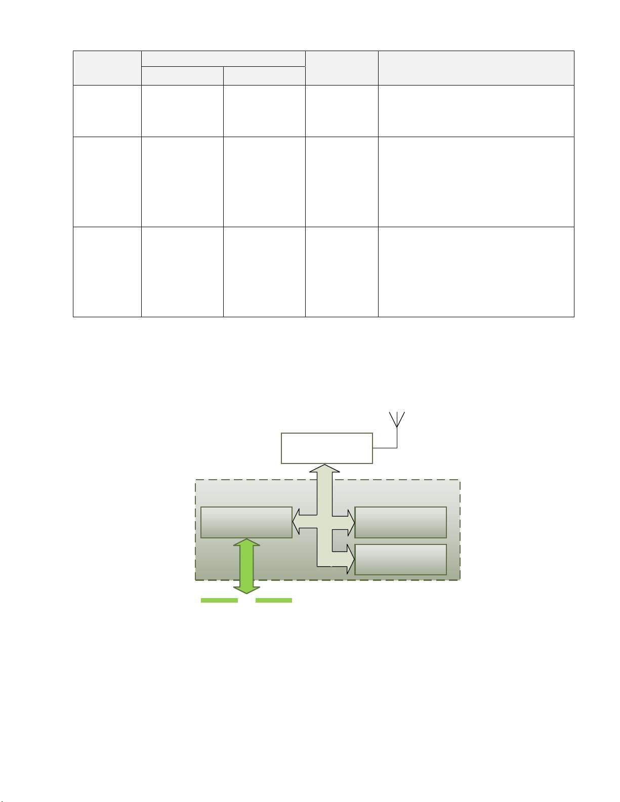
2.1Hardware Block Diagram ................................................................................................. 7
2.2Status LED ...................................................................................................................... 8
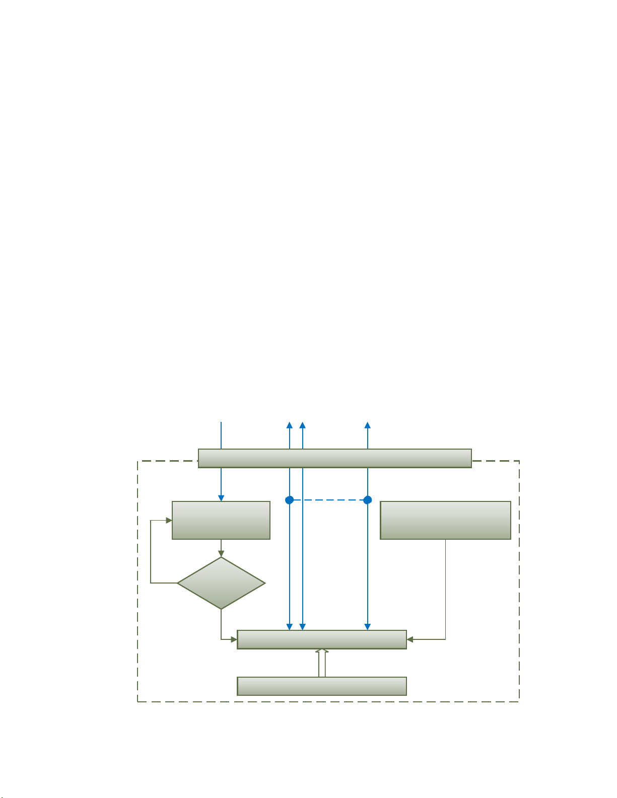
2.3Logical Structure .............................................................................................................. 9
2.3.1Communication Device ............................................................................................. 10
2.3.1.1UDP Protocol ...................................................................................................... 10
2.3.1.2TCP Protocol ...................................................................................................... 11
2.3.2Web Server ............................................................................................................... 12
2.3.3Network Discovery .................................................................................................... 12
2.3.4Network Processor .................................................................................................... 12
3CONVERTER CONFIGURATION ..................................................................................... 13
3.1Wireless Connection ...................................................................................................... 13
3.2Changing Configuration Parameters ............................................................................. 15
3.3Wi-Fi Configuration ........................................................................................................ 17
3.4IP Network Configuration ............................................................................................... 19
3.5CAN Configuration ......................................................................................................... 21
3.5.1CAN ID Range Filters ................................................................................................ 22
3.5.2CAN ID Mask Filters .................................................................................................. 23
4CONVERTER DIAGNOSTICS ........................................................................................... 25
4.1Health Status ................................................................................................................. 26
4.2Converter Rebooting ..................................................................................................... 26
5FIRMWARE UPDATE ........................................................................................................ 28
5.1Uploading the New Firmware ........................................................................................ 28
5.2Applying the New Firmware ........................................................................................... 29
6CONVERTER DEPLOYMENT ........................................................................................... 31
6.1Wireless CAN Bridge ..................................................................................................... 31
6.2Direct Wireless Connection ........................................................................................... 31
6.3Wireless CAN Station .................................................................................................... 32
6.4Wireless CAN Bridge Configuration Example ................................................................ 33
7CONVERTER DISCOVERY .............................................................................................. 35
8TECHNICAL SPECIFICATIONS ........................................................................................ 36
8.1Power Supply ................................................................................................................ 36
8.2Wi-Fi Port ...................................................................................................................... 36
8.3CAN Port ....................................................................................................................... 37
8.4LED Indicator ................................................................................................................. 37
8.5General Specifications ................................................................................................... 37
8.6RF Regulatory Restrictions ............................................................................................ 37
8.7RF Module Compliances ............................................................................................... 38
8.7.1Module FCC Statement ............................................................................................. 38
8.7.2Module CAN ICES-3(B) and NMB-3(B) Statement ................................................... 38
8.7.3Module EC Declaration of Conformity ....................................................................... 39
8.8Accessories ................................................................................................................... 39
8.9Connector ...................................................................................................................... 39
8.10Housing ......................................................................................................................... 40
9THIRD PARTY SOFTWARE LICENSE NOTICES ............................................................ 41
10VERSION HISTORY .......................................................................................................... 44

UMAX141200. Wi-Fi to CAN Converter. Version 1 Page: 6-44
1 INTRODUCTION
The following user manual describes architecture, functionality, and configuration parameters
of the Wi-Fi to CAN Converter. It also contains technical specifications and installation
instructions of the converter.
The user should check whether the application firmware installed in the converter is covered
by this user manual. It can be done using any web browser connected to the converted ether
directly over the Wi-Fi connection or indirectly over the LAN, see: Configuration Parameters
section for more details.
The user manual is valid for application firmware with the same major version number as the
user manual. For example, this user manual is valid for any application firmware version 1.xx.
Updates specific to the user manual are done by adding letters: A, B, …, Z to the user manual
version number.

UMAX141200. Wi-Fi to CAN Converter. Version 1 Page: 7-44
2 CONVERTER DESCRIPTION
The Wi-Fi to CAN Converter is a simple device converting CAN frames into UDP or TCP IP
datagrams and sending them over a wireless Wi-Fi network. The device can also convert the
received UDP or TCP datagrams into CAN frames.
The converter has one CAN port. It supports a high-speed CAN with a configurable baud rate
up to 1Mbit/s and a dual-band 2.4GHz and 5GHz 802.11 a/b/g/n Wi-Fi. All standard and
extended CAN frames, including data and remote frames, are supported.
The converter can work in a station (STA) or access point (AP) mode. The wireless connection
is provided by an internal antenna to maintain ruggedness. A three-color LED on the housing
displays an internal state of the converter.
The converter contains a web server to setup configuration parameters and monitor the
internal state of the converter using a web browser. The user can also update the converter
firmware over the air (OTA) using the web browser.
The converter has two digital inputs. One of them is used to switch the converter to a default
AP mode and then access it using a standard wireless device (e.g., a laptop or a smartphone).
The second one can be used to disable all Wi-Fi communication.
A simple command-line AxioDisc.exe Windows application is provided to locate a converter
on the LAN.
To ensure low latency in processing CAN messages, the converter software runs under control
of a real-time operating system.
The converter is designed to work on off-road machinery or in a harsh industrial environment
with power transients, high humidity, and vibrations.
2.1 Hardware Block Diagram
The converter hardware block diagram is presented in Figure 1.
The converter is powered from a standard automotive 12V or 24V battery. Reverse polarity,
overvoltage, and transient protection is provided.
The CAN port is connected to a powerful 32-bit ARM Cortex-M4 microcontroller that runs IP
protocol stack and all IP to CAN conversion logic.
The wireless part is provided by the Texas Instrument CC3135 network processor (NWP),
which sends and receives IP messages over a wireless Wi-Fi network, establishes and
maintains the wireless connection in 2.4GHz or 5GHz Wi-Fi frequency band.
The converter has two digital inputs. They have internal pull-up resistors and are activated by
connection to the digital ground (DIN_GND pin).
A three-color RGB Status LED indicates the internal state of the converter.

UMAX141200. Wi-Fi to CAN Converter. Version 1 Page: 8-44
Figure 1. The Converter Hardware Block Diagram
2.2 Status LED
The Status LED on the housing displays the internal state of the converter the following way,
see Table 1:
Table 1. Converter Status LED
LED Subsystem state Converter
Status Description
Wi-Fi CAN
Green
(steady or
blinking)
Connected Active Normal
Operation
CAN and Wi-Fi ports are ready for
communication. If blinking, data is
being transferred between CAN and
Wi-Fi ports.
Steady
Yellow
Disconnected Active Waiting for
Wi-Fi
Connection
Wi-Fi port is enabled but not
connected to the user’s STA or AP.
Waiting for the Wi-Fi connection
Flashing
Yellow
Disconnected Active Waiting for
Wi-Fi
Connection
with Default
Settings
Wi-Fi port is enabled with default AP
settings but not connected to the
user’s STA. Default settings have
been activated by connecting the
DIN_nWIFI_DEFAULT pin to
DIN_GND on powe
r
-up.
Steady
Violet
Disconnected Active Wi-Fi
Hibernated
Wi-Fi port is disabled.
DIN_nWIFI_HIB pin is connected to
DIN_GND. The Wi-Fi NWP is in the
hibernation (low power) state with RF
transmitter and receiver disabled.
EMIFilter.
TransientandReverse
PolarityProtection
BAT+
BAT‐
PowerSupply
DigitalInput#1
ARMCortex‐M4
Microcontroller
CAN
CAN_HI
CAN_LO
12V,24V
Nominal
EEPROM
DigitalInput#2
DIN_nWIFI_DEFAULT
DIN_nWIFI_HIB
FLASH
CC3135
NWP
Internal
Antenna
+3.3V
DIN_GND
PTC
Resettable
Fuse
2.4GHz
5GHz
RGBStatusLED

UMAX141200. Wi-Fi to CAN Converter. Version 1 Page: 9-44
LED Subsystem state Converter
Status Description
Wi-Fi CAN
Steady
Red
Any Passive CAN Error CAN controller is in the Passive state
due to CAN errors.
Check the CAN line connection,
baud rate, terminating resistors.
Flashing
Red
Any Any System
Error
Unrecoverable system error. Device
failure. This status should not
happen during the normal converter
operations.
Try to perform the hardware reset by
cycling the power. Contact Axiomatic
if this does not help.
Alternate
Green/Red
Disconnected Disconnected Bootloader
Mode
The converter will go to the
Bootloader mode for a short period of
time to flash the new firmware
uploaded through the converter
website. It will leave the Bootloader
mode automatically after the flashing
operation is ove
r
.
2.3 Logical Structure
The Wi-Fi to CAN Converter is internally organized as a system of interconnected independent
modules. It includes the following internal modules: Communication Device, Web Server, and
Network Discovery. They are connected to an external Wi-Fi network via the Network
Processor, see Figure 2:
CAN
Communication Device Web Server
IP Network
Network Discovery
Network Processor
Wi‐FiAntenna
Figure 2. Converter Logical Structure
All internal converter modules are accessed using IP (internet protocol) network interface.
They share the same address, mask and default gateway settings assigned to the
Communication Device but use different communication ports and protocols.
The Network Processor module connects all internal converter modules to an external IP
network via a wireless Wi-Fi connection.

UMAX141200. Wi-Fi to CAN Converter. Version 1 Page: 10-44
2.3.1 Communication Device
The Communication Device module is responsible for the protocol conversion between CAN
and IP networks. It utilizes a proprietary communication protocol to communicate CAN
messages and other auxiliary information over the IP network.
The Communication Device supports a client/server communication model. In this model, the
converter has a primary server role, allowing external clients to establish independent
connections with the converter.
In addition to the server role, the converter can also act as a client, if the Auto Connect to
Remote configuration parameter is set to Yes. In this case, the converter will try to establish a
connection with a customer specified remote server.
The total number of remote connections is limited to 10. If the CAN network traffic is high, this
number should be further reduced, or the connections will become unstable due to limited
internal resources of the microcontroller, which are dynamically allocated between open
connections.
The Communication Device can use either UDP or TCP IP, depending on the value of the
Device Port Type configuration parameter.
2.3.1.1 UDP Protocol
The UDP protocol is set by default. Since it is a connectionless protocol, one data socket
serves all device communication needs, see Figure 3.
New
connection?
Identify new connection
by analyzing incoming
traffic
No
Yes
Input/Output Communication
Up to 10
connections
Connection Maintenance
Server Client
Server connection will
expire, if inactive
Client co nnection will
never expire
DeviceIpAddr:DevicePort
Device Communication Flow
Data Socket
Initialize remote connection if
AutoconnectToRemote==True
Figure 3. Communication Device. UDP Protocol

UMAX141200. Wi-Fi to CAN Converter. Version 1 Page: 11-44
All connections with the device are virtual. On the server side, the device analyzes the
incoming traffic to check for the new connections. Once a new IPAddress:Port combination is
detected, the connection is established, and the device starts sending CAN data with
Heartbeat messages to the new node.
There are no restrictions on the IP address and port for the incoming connections.
If a client-side is activated by the Autoconnect to Remote configuration parameter, the device
will automatically start sending CAN data with Heartbeat messages to the remote node on
start-up.
To ensure that the device does not send data to not functioning (“dead") or disconnected
nodes, the server-side connections will expire in 10 sec of inactivity, when no valid data is
received from the remote node. The client-side connection will never expire.
2.3.1.2 TCP Protocol
When TCP protocol is used, the Communication Device opens an individual data socket for
each device connection, see: Figure 4.
Data Socket
New
connection?
Listen to incoming
connections
No
Yes
Input/Output Communication
Try to connect to remote, if
AutoconnectToRemote==True
Connection
established?
Yes
No
Up to 10
connections
Server Client
DeviceIpAddr:DevicePort
Device Communication Flow
Data Socket Data Socket
Accept Connection
Data Socket
Dev i ceI p Ad dr:Dev icePo rt Dev i ceI p Ad dr:A ny Por t
Listen
Socket
Figure 4. Communication Device. TCP Protocol
The server side opens a listening socket for incoming connections. Once a connection is
accepted, a new data socket is created to handle input/output communication with the remote
node. There are no restrictions on the IP address and port for the incoming connections,
similar to the UDP mode.
On the client side, if Auto Connect to Remote is set to Yes, a data socket is created for
connection with the remote node. A random free port number is assigned to the socket. If the
connection drops, the device will try to automatically reconnect with the node to maintain the
client connection.

UMAX141200. Wi-Fi to CAN Converter. Version 1 Page: 12-44
2.3.2 Web Server
The Web Server provides a user front-end interface with the converter. It runs a dynamic
website that shows: the converter general information, configuration parameters, and the
converter real-time diagnostics.
The user can also change configuration parameters and upload the new firmware through this
website.
The web browser should support JavaScript.
2.3.3 Network Discovery
The Network Discovery module supports a proprietary Axiomatic discovery protocol. It allows
to locate a converter with unknown IP address and/or web server port on a LAN using a simple
Axiomatic discovery application AxioDisc.exe.
2.3.4 Network Processor
The Network Processor module is responsible to maintain a wireless Wi-Fi connection with an
external IP network. It can work either in a station (STA) or an access point (AP) mode. The
connection can be secured with a password using WEP or WPA / WPA2 security protocols.
The user has an ability to select an RF channel in either 2.4GHZ or 5GHz frequency band in
the AP mode. Up to 4 station can be simultaneously connected to the module in the AP mode.

UMAX141200. Wi-Fi to CAN Converter. Version 1 Page: 13-44
3 CONVERTER CONFIGURATION
The converter supports configuration over the internal website running on the device
embedded web server. To configure the device, the user should establish a wireless Wi-Fi
connection between the converter and a user’s device, which can be, for example, a laptop or
a smartphone.
3.1 Wireless Connection
The converter default wireless settings, configured at the factory, are presented in Table 2.
The user’s device should use these settings to connect to the Wi-Fi to CAN converter.
Table 2. Wi-Fi Default Settings
Paramete
r
Default Value
Connectivity Mode
A
P (Access Point)
Country/Region Code USA
A
P Channel 6 (2.4GHz frequency band)
Security WPA / WPA21
SSID (Network Name)
A
xiomatic_CANWiFi
Password CANWiFi_16025
1WPA / PSK and WPA2 / PSK security types, or a mixed mode of WPA / WPA2 PSK security type
(TKIP, AES, mixed mode).
In case the converter settings were changed at the customer site, the default settings can be
activated by pulling the DIN_nWIFI_DEFAULT input low on power-up. This can be achieved by
connecting the DIN_nWIFI_DEFAULT input to DIN_GND. The Status LED on the housing will
be flashing yellow in this case.
The default Wi-Fi settings, activated by the DIN_nWIFI_DEFAULT input, do not rewrite the
original Wi-Fi settings in the von-volatile memory. The converter will return to its original
settings after the next power-up or reboot.
When the default settings are used, the converter will appear on the list of available Wi-Fi
networks on the user’s device, see an example on Figure 5.
Figure 5. Converter AP on the List of Available Networks
The user should connect to the converter using the default password “CANWiFi_16025” and
with the manual IP settings. The assigned IP address should not conflict with the converter
Device IP Address (default value 192.168.0.34) and with addresses of other devices
connected to the user’s device, if any. See an example on Figure 6.
When the wireless connection is established, the user can access the converter embedded
web server using any web browser on their device. The web browser should be pointed to the

UMAX141200. Wi-Fi to CAN Converter. Version 1 Page: 14-44
Device IP Address (default value 192.168.0.34). It is not necessary to specify the Web Server
Port if the web server uses a standard port 80, which is set by default.
Figure 6. User Manual IP Settings
In case the Device IP Address or port has been changed and the value is lost, the Axiomatic
AxioDisc.exe Windows console application can be used to recover the values, see
Converter Discovery section for details.
After a successful connection, the user will see the device home page, see Figure 7.
Figure 7. Converter Home Page

UMAX141200. Wi-Fi to CAN Converter. Version 1 Page: 15-44
The home page shows the device information, including the converter part number, serial
number, and firmware version. It also shows Wi-Fi, IP Network and CAN configuration
parameters including the status of CAN ID Range and CAN ID Mask input filters.
You will need to allow the site to run JavaScript (this setting is default in the majority of web
browsers). If JavaScript is disabled, the website will show a message asking to activate
JavaScript at the top of the web page, see Figure 8.
Figure 8. Enable JavaScript Prompt
The IP Network configuration parameters are combined into Server and Client groups for
convenience.
The IP Network and CAN configuration parameters have tooltips clarifying their meaning, see
Figure 9.
Figure 9. A Tooltip for the “Auto Connect to Remote” Configuration Parameter
3.2 Changing Configuration Parameters
The converter configuration parameters are grouped into the following configuration pages: Wi-
Fi Settings, IP Network/CAN Settings, CAN ID Range Filters and CAN ID Mask Filters. The
configuration pages can be reached by clicking on their links on the left side of the website,
see Figure 10.
Each configuration web page has fields to enter values of the configuration parameters and
three buttons: Save Settings, Discard Settings, and Set Defaults, see Figure 10. The Wi-Fi
Settings page has the fourth button: Reboot Converter since the Wi-Fi settings are applied only
after the converter reboot.

UMAX141200. Wi-Fi to CAN Converter. Version 1 Page: 16-44
Figure 10. IP Network/CAN Settings Configuration Webpage
The Save Settings button will save configuration parameters in non-volatile memory. Except
for the Wi-Fi settings, the appropriate converter subsystems will be restarted without rebooting
of the whole converter and the new parameters will be applied immediately. If necessary, the
rebooting is available from the Diagnostics or Wi-Fi Settings page.
The Discard Changes button will bring back the original converter settings before they have
been changed on the website. In case the user leaves the page without saving, all changes will
be also discarded.
The Set Defaults button will load the default values of the configuration parameters into the
data fields on the configuration page.
The configuration parameters have tooltips for the user convenience.
When the user presses Save Settings button, the web page runs a script to check the validity
of the new configuration parameters before uploading them to the web server. For example,
the following alert message will be displayed if the user enters the same value for the Device
Port and the Web Server Port, see Figure 11.
Figure 11. Settings Alert. Error in Configuration Parameters
The website messages should be enabled (not suppressed) in the browser to see this and
other feedback messages.

UMAX141200. Wi-Fi to CAN Converter. Version 1 Page: 17-44
After pressing the Save Settings button and saving the configuration parameters, the converter
replies with a confirmation message showing a result of the saving operation. For example, if
the user has successfully changed an IP Network/CAN configuration parameter, the following
message will appear, see Figure 12.
Figure 12. Settings Alert. Configuration Parameters have been Changed Successfully
3.3 Wi-Fi Configuration
The Wi-Fi configuration parameters control the converter wireless connection. Their status is
shown on the home page, see Figure 13.
Figure 13. Wi-Fi Configuration Status
The user can change the Wi-Fi configuration parameters on the Wi-Fi Settings configuration
page, see Figure 14.
The Wi-Fi Mode and Country configuration parameters apply to both: Station and Access Point
modes. Parameters in Station and Access Point modes are set separately.
The Wi-Fi configuration parameters are presented in Table 3. The converter needs to be
reboot for the changes to be applied. Remember that connection with the user’s device
running the web browser can be lost after the reboot.

UMAX141200. Wi-Fi to CAN Converter. Version 1 Page: 18-44
Figure 14. Wi-Fi Settings Configuration Page
Table 3. Wi-Fi Configuration Parameters
Configuration
Parameter Default Value Range Description
Wi-Fi Mode Access Point {Access Point,
Station}
In the Station (STA) mode, the
converter connects to an external Wi-
Fi access point (AP), for example a
router. In the Access Point (AP) mode,
other wireless devices are connected
to the converter.
Country USA {List of countries and
regions of the world}
Select a country or region where the
converter is used. Defines the list of
RF channels used by the converter.
This is necessary to conform with local
laws since incorrect settings may
cause RF interference.
Station Mode
Wireless
Network
Name
Axiomatic_CANWiFi ASCII String, 1…32
characters
SSID of the AP the converter will try to
connect
Security WPA2 {Open, WEP1,
WPA22}
Security protocol of the wireless
connection with the AP. WPA2 applies
to both: WPA and WPA2 protocols. No
security if Open

UMAX141200. Wi-Fi to CAN Converter. Version 1 Page: 19-44
Configuration
Parameter Default Value Range Description
Password CANWiFi_16025 ASCII String,
13...26 characters
for WEP, 8...64
characters for WPA2
Password of the AP. Not used if
Security is Open
Access Point Mode
Wireless
Network
Name
Axiomatic_CANWiFi ASCII String, 1…32
characters
SSID of the converter
Security WPA2 {Open, WEP1,
WPA22}
Security protocol of the wireless
connection used by the converter.
WPA2 applies to both: WPA and
WPA2 protocols. No security if Open
Password CANWiFi_16025 ASCII String,
13...26 characters
for WEP, 8...64
characters for WPA2
Password of the converter. Not used if
Security is Open
RF Channel 6 {List of available
channels depends
on the selected
Country}
Select an RF channel with the
minimum interference from 2.4GHz or
5GHz frequency range. Only channels
allowed in the selected country/region
will be shown in the list of available
channels.
1WEP open security.
2WPA / PSK and WPA2 / PSK security types, or a mixed mode of WPA / WPA2 PSK security type
(TKIP, AES, mixed mode).
3.4 IP Network Configuration
The converter IP network configuration parameters can be changed on the IP Network/CAN
Settings web page, see Figure 15.
The converter MAC Address shown on the Home page is a read-only parameter. The user-
changeable network configuration parameters are presented in Table 4.
Table 4. Network Configuration Parameters
Configuration
Parameter Default Value Range Description
Device IP Address 192.168.0.34
A
ny IP address The converter IP address1
Device Port 4000 Any port value except
the Web Server Port
and the Discovery
Protocol Port
The device server port. The
device is listening to this port for
incoming connections. The
Discovery Protocol Port (35100)
and the Web Server Port should
not be used.
Device Port Type UDP {UDP, TCP} Type of the IP protocol used by
the device. The device server and
client use the same IP protocol.
Web Server Port 80 Any port value except
the Device Port and the
Discovery Protocol Port
The communication port of the
converter web server
Device Subnet Mask 255.255.255.0
A
ny IP address The converter subnet mask1

UMAX141200. Wi-Fi to CAN Converter. Version 1 Page: 20-44
Configuration
Parameter Default Value Range Description
Device Default
Gateway 192.168.0.1 Any IP address The converter default gateway1
Auto Connect to
Remote No {No, Yes} The device client state. When the
Auto Connect to Remote is Yes,
the device client is activated, and
the device will try to establish a
connection with the remote server.
Remote IP Address 192.168.0.35 Any IP address The remote server IP address.
Used by the device client when
the Auto Connect to Remote is
Yes.
Remote Port 4000 Any port value The remote server port. Used by
the device client when the Auto
Connect to Remote is Yes.
1Common parameter shared with all internal converter modules including the embedded web server.
Figure 15. IP Network/CAN Configuration Page
When the device client is activated by setting the Auto Connect to Remote configuration
parameter to Yes, the converter will still act as a server accepting connections on the Device
This manual suits for next models
1
Table of contents
Other AXIOMATIC Media Converter manuals